IMPACT REDUCTION HELMET
US20140208486A1
2014-07-31
13/749,873
2013-01-25
Abstract:
An impact reduction helmet and method are disclosed. The helmet and method include an inner frame having interior pads that rest on a person's head and a second frame coupled to the first frame with shock absorbers wherein the shock absorbers are larger in the section of the helmet near the rear of the helmet and shorter in the section closer to the front of the helmet in order to move the rotational center of the helmet closer to the rotational center of the head. The first frame and second frame are also spaced farther apart than prior art helmets to increase the distance available for impact absorption.
Interested in similar patents?
Get notified when new applications in this technology area are published.
Classification:
A42B3/0453 » CPC main
Helmets; Helmet covers ; Other protective head coverings; Parts, details or accessories of helmets; Accessories for helmets; Detecting, signalling or lighting devices Signalling devices, e.g. auxiliary brake or indicator lights
A42B3/04 IPC
Helmets; Helmet covers ; Other protective head coverings Parts, details or accessories of helmets
Description
BACKGROUND
The present invention generally relates to helmets that reduce impact-related accelerations to a person's head and brain. High accelerations of the head or brain cause traumatic brain injury (TBI), also known as a concussion or as MTBI, which is an acronym for mild traumatic brain injury or moderate traumatic brain injury.
Concussions from multiple head blows and the resulting chronic traumatic encephalopathy (CTE) have caused several professional football players to commit suicides. Concussions also occur in college and high school football, in other sports such as ice hockey and cycling, and in military operations. Studies of head impacts in football show that concussions occur when a person receives one or more hits that induce linear head accelerations of greater than about 80 g or rotational head accelerations of greater than about 5000 rad/sec2.
An analysis of the speed at impact shows that a world-class sprinter can run about 10 m/sec (23 miles/hour). A 4-minute mile is equivalent to 6.7 m/sec, which is about ⅔ of the speed of a world-class sprinter. Football helmet test standards use 12 mile/hour impacts, which equals approximately 5 m/sec or half of the speed of a world-class sprinter. The padding on a typical football helmet is less than 1 inch thick. From physics:
x=(0.5) a t2
v=a t (if acceleration is constant)
where: x is displacement, v=velocity, a=acceleration, and t=time
If one solves the above equations for constant deceleration from 5 m/sec to 0 m/sec in 1 inch ( 1/40th of a meter or 25 millimeters), the result is 500 m/sec2 or approximately 50 g (the acceleration of gravity is approximately 10 m/sec2). This means that padding that perfectly decelerates from 5 m/sec to 0 in 25 mm (1 inch) could theoretically provide a constant deceleration rate of 50 g. However, the padding on a helmet is far from this optimum in that (a) it doesn't provide a full inch of travel in actual use and (b) it doesn't provide the constant resistive force needed for perfect linear deceleration. Furthermore athletes may sprint at speeds that create an impact having an initial velocity of greater than 12 miles per hour. A calculation of rotational accelerations based on typical current football helmet configurations shows that a one inch of rotation of the outer shell of a 12 inch helmet to stop an initial radial velocity of 12 miles/hour (5 msec) at a radius of 6 inches generates an angular acceleration of about 5000 rad/sec2 which is the concussion threshold as the threshold for linear acceleration (or deceleration) of the head. These theoretical calculations are consistent with the medical data that shows that concussions occur frequently in high school, collegiate, and professional football. Helmet manufacturers and the test labs understand the inability for current helmet designs to prevent concussions and place the following warning message on all football helmets sold in the USA: “No helmet can prevent all head and neck injuries a player might receive while participating in football”. Many warning labels on football helmets, such as those made by Riddell, go further in their warning label and also state that: “ . . . Contact in football may result in CONCUSSION-BRAIN INJURY which no helmet can prevent . . . ”
It is desired to make a helmet system that is fundamentally superior in reducing the chance of concussions.
BRIEF DESCRIPTION OF THE DRAWINGS
The present invention will be better understood on reading the following detailed description of non-limiting embodiments thereof, and on examining the accompanying drawings, in which:
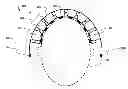
FIG. 1A is a horizontal section of a prior art helmet on a person's head;
FIG. 1B is an isometric view of a prior art helmet pad;
FIG. 1C is a force-displacement curve for a prior art helmet pad;
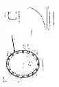
FIG. 2A and FIG. 2B show the theory of operation of a helmet when subjected to an impact force at an arbitrary point;
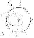
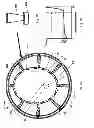
FIG. 3A is a horizontal section of an impact reduction helmet on a person's head;
FIG. 3B is an isometric view of a head conforming pad and a shock absorption element in series;
FIG. 3C is a force-displacement curve for a head confirming pad helmet pad and a shock absorption element in series;
FIG. 4 shows a vertical section of an alternate embodiment helmet;
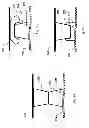
FIGS. 5A, 5B, and 5C are detailed views of two layers of elastically-resilient impressions in a serial configuration for use in a helmet;
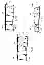
FIGS. 6A, 6B, and 6C are detailed views of elastically-resilient impressions in a parallel configuration for use in a helmet;
FIG. 7A shows a configuration of an embodiment of an improved helmet that incorporates a single-use impact reduction material; and
FIG. 7B is a force-displacement curve for a single-use constant force impact reduction material.
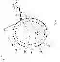
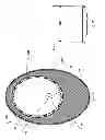
FIG. 8 is an oval helmet with a rotationally compliant cover.
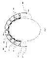
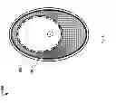
FIG. 9 is an oval helmet with a multi-element rotationally compliant cover.
To assist in the understanding of one embodiment of the present invention, the following list of components or features and associated numbering found in the drawings is provided herein:
Number Component or Feature
F Typical impact
Ft Tangential force
Fn Normal force
94 Rotational center of head
96 Spinal cord
98 Person's head
100 Prior art helmet
102 Hard shell
104 Pad (prior art)
106 Center of hard shell
200 Impact reduction helmet
202 Impact reduction helmet outer shell
204 Head-conforming pad
205 Pad frame
206 Helmet rotational center
208 Shock absorption element
210 Constant force region
212 Impact reduction helmet inner frame
214 Rotational coupler
300 Alternate embodiment helmet
304 First elastically-resilient impression
306 Second elastically-resilient impression
316 Orifice
320 Sensor
322 Sensor
400 Single use impact reduction helmet
408 Single use impact material
500 Oval helmet with rotationally compliant cover
502 Rotationally compliant cover
600 Oval helmet with multi-element rotationally compliant cover
602 Multi-element rotationally compliant cover
It should be understood that the drawings are not necessarily to scale. In certain instances, details that are not necessary for an understanding of the invention or that render other details difficult to perceive may have been omitted. It should be understood that the invention is not necessarily limited to the particular embodiments illustrated herein.
DETAILED DESCRIPTION
The ensuing description provides preferred exemplary embodiment(s) only, and is not intended to limit the scope, applicability or configuration of the disclosure. Rather, the ensuing description of the preferred exemplary embodiment(s) will provide those skilled in the art with an enabling description for implementing a preferred exemplary embodiment. It should be understood that various changes could be made in the function and arrangement of elements without departing from the spirit and scope as set forth in the appended claims.
Specific details are given in the following description to provide a thorough understanding of the embodiments. However, it will be understood by one of ordinary skill in the art that the embodiments may be practiced without these specific details.
Referring now to the drawings, FIG. 1A shows a horizontal section of a prior art helmet 100 on a person's head 98. The person's spinal cord is shown at 96. The rotational center of the head is shown at 94. The prior art helmet 100 is comprised of a hard shell 102 and a set of pads 104 that compress to fit the person's head 98. Because the spinal cord 96 is located to the back of the person's head 98 and the pads 104 provide an approximately constant spacing between the person's head 98 and the hard shell 102, the center of the hard shell 106 is quite a distance from the rotational center of the head 94. A typical impact, shown at F, when applied to a prior art helmet generates a high rotational moment as will be further described below in reference to FIG. 2.
FIG. 1B shows an isometric view of the pad 104. FIG. 1C depicts the force-displacement curve of the pad 104 in actual use. A typical prior art helmet pad 104 has a typical displacement of less than 20 mm in actual use before the pad is completely compressed. The force-displacement curve has a positive slope throughout its entire range. There is an initial force required before any displacement occurs because the pad is pre-loaded against the person's head (98 in FIG. 1A). This preload is shown by the y-axis intercept at 0 mm of displacement in FIG. 1C. The force rises steeply as displacement increases and the rate of increase per unit of displacement increases (i.e. the slope of the curve increases) until the displacement approaches the maximum displacement of the pad, at which point, the slope becomes asymptotically vertical because the pad 104 is fully compressed. This asymptotic line is shown at a value of 20 mm in FIG. 1C. The shape and characteristics of the force-displacement curve shown in FIG. 1C is typical of that for prior art helmets.
FIG. 2A provides a 2-dimensional view of the theory of operation of a helmet by showing the same prior art helmet, 100 as in FIG. 1A, on a player's head 98. The person's spinal cord 96, rotational center of the head 94, hard shell 102, and center of the hard shell 106 are also shown. The force F is shown impacting the hard shell 102 at an arbitrary point. In actual use, impacts F can occur in any location and any direction on the exterior of a helmet. The impact F can be decomposed into: a force Ft that is tangential to the curvature of the exterior of the helmet at the point of impact and a force Fn that is normal to the exterior of the helmet at the point of impact. The tangential component of force Ft generates a rotational moment on the helmet 100 and hence on the spinal cord 96. The magnitude of this rotational moment depends on: (a) the coefficient of friction between the helmet exterior (in this case the hard shell 102) and the body that produced force F; (b) the perpendicular distance between the point of impact and the rotational center of the head 94, a distance shown at y; and (c) whether the collision is elastic, inelastic, or partially elastic. The tangential component of force Ft can also generate an axial force on the hard shell 102 and hence on the spinal cord 96. The magnitude of this axial force depends on (a) the coefficient of friction between the helmet exterior (in this case the hard shell 102) and the body that produced impact F and (b) whether the collision was elastic, inelastic, or partially elastic. Based on the preceding and as shown in FIG. 2A, one can minimize the effect of the tangential component of force Ft on the spinal cord 96 by minimizing the coefficient of friction between the helmet exterior and the body that produced force F and by making the center of curvature of the helmet exterior at the point of impact align as closely as possible with the rotational center of the head 94. More specifically the tangential component of force Ft will produce no force on the spinal cord 96 if (a) there is a zero coefficient of friction between the helmet exterior and the body that produced impact F or (b) if the center of curvature of the helmet exterior at the point of impact is in the same location as the rotational center of the head 94 and the helmet exterior is coupled to the rest of the helmet in a way that allows the helmet exterior to rotate freely around the other elements of the helmet. In order for the center of curvature of the helmet exterior to be in the same location as the rotational center of the head 94 for all tangential forces at all locations on the helmet, the helmet exterior must be spherical and the center of this spherical helmet must be at the same location as the center of the rotation of the person's head 94. This idealized configuration is shown in FIG. 2B. Referring to FIG. 2B, the rotational center of the head 94 has been aligned with the inertial center of an improved outer shell 202 having an inertial center 206 that is co-located with the rotational center of the head 94.
Further referring to FIG. 2A, the normal force Fn creates an axial force on the spinal cord 96. The normal force Fn can also create a bending moment (i.e. rotational force) on the spinal cord 96 if the center of the radius of curvature of the helmet exterior at the point of impact is not aligned with the rotational center of the head 94. For the geometry shown, a line drawn perpendicular to the tangent line a the point of impact will intersect the center of the hard shell 106. Therefore, for the geometry and impact shown, the size of bending moment created by Fn equals the offset between the center of the hard shell 106 (illustrated as x in FIG. 2A) multiplied by the magnitude of the normal force Fn. Note that if there is friction between the impact source and the hard shell 102 and the shell 102 is not free to rotate about the person's head 98, then the tangential force Ft will produce an additional bending moment equal to Ft multiplied by the perpendicular distance between a line tangent to the point of impact on the hard shell 102 and a parallel line that intersects the rotational center of the head 94. This perpendicular distance is shown at y in FIG. 2A.
Referring to FIG. 2B, the normal force Fn produces no bending moment if the radius of curvature of the helmet exterior at the point of impact (which is the same as the center of the helmet shell if the shell is spherical) is aligned with the rotational center of the head 94. By comparing FIG. 2A with FIG. 2B, one can see that there is no “x” dimension in FIG. 2B.
FIG. 3A shows a horizontal section view of an impact reduction helmet 200 on a person's head. Like in FIG. 1A, the person's head is shown at 98, the person's spinal cord is shown at 96, and the rotational center of the head is shown at 94. The embodiment of the impact reduction helmet 200 in FIG. 3A has several improvements over the prior art helmet 100 of FIG. 1A. A first improvement, shown in FIG. 3A, is that the head-conforming pads 204 are thinner. The head-conforming pads 204 are configured to fit inside of a pad frame 205 and press against the person's head 98. In the improved helmet 200, the pad frame 205 is separate from the hard shell, shown at 202. The pad frame 205 is sized and shaped to conform as closely as possibly to the person's head 98, and could be custom fitted to each user. The pad frame 205 can be sized and shaped independently of the size and shape of the hard shell 202. By having a pad frame 205 that conforms as closely as possible to a person's head 98, the head-conforming pads 204 can be thinner than the pads 104 in the prior art design (FIG. 1A). In the prior art helmet (shown in FIG. 1A) the prior art pads 104 were configured to perform two functions: (a) to provide a comfortable fit on the person's head 98 and (b) to provide shock absorption. In the improved design, 200 FIG. 3A, shock absorption elements shown at 208 have been added to the system and these shock absorption elements 208 can be independent of the head-conforming pads 204. In the prior art shown in FIG. 1A, the pads 104 needed to be relatively thick to provide sufficient compliance to fit both big heads and small heads into the same shell 202. The improved helmet 200 of FIG. 2A allows a closer fitting of a pad frame 205 to a person's head 98. One of the ways to accomplish this closer fitting is to make the pad frame 205 from material that is initially flexible to fit the person's head 98 and subsequently hardened once the fit has been determined Another technique for producing a custom pad frame 205 is to make a 3-dimensional scan of the person's head 98 and then to manufacture the custom pad frame 205 using a 3-dimensional printer. The methods for making this custom pad frame 205 can be any method or technique capable of being understood by anyone skilled in the art.
Further referring to FIG. 3A, the shell 202 of the impact reduction helmet 200 is spherical. The use of a spherical shell 202 makes it is possible to minimize or completely eliminate the relationship between a tangential components of impact force (Ft shown in FIG. 2A) and any resulting rotational forces on the person's spinal cord 96. Rotational forces on a person's spinal cord 96 can be minimized or eliminated by either (a) minimizing friction between the source of impact and the spherical shell 202 or (b) allowing the spherical shell 202 to rotate relative to an inner frame member, shown at 212, through the use of rotational couplers 214. Note that the improvements shown in FIG. 3A can either be used with a spherical shell, which can allow rotation about two perpendicular axes or with a shell that has a circular geometry in one axis, but is non-circular about an axis perpendicular to this axis. In the latter case, the helmet could rotate freely about an axis aligned with the rotation of the spinal cord, but would not rotate about an axis perpendicular to this spinal rotation axis.
Further referring to FIG. 3A, the rotational center of the shell 202 is shown at the point labeled 206. This rotational center 206 is brought much closer to the rotational center of the head 94, than in the prior art shown in FIG. 1A and FIG. 2. This repositioning of the rotational center 206 backwards on the person's head 98, further reduces the rotational forces as explained previously when describing the theory of operation and FIG. 2A. In an ideal case, the rotational center 206 would be the same as the rotational center of the head 94. Note that the center of the radius of curvature of a circle is the same as the center of the circle, and the same applies to a sphere. Thus, the center of curvature for a shell having a circular geometry will be the same as the rotational center 206. It is also the case that the center of the moment of inertia of a circle, or anything having a circular geometry will be the rotational center of that circle or item having a circular or spherical geometry.
Further referring to FIG. 3A the pad frame 205 and shell are connected through shock absorption elements 208. In the embodiment showing in FIG. 3A, the shock absorption elements 208 are fixed at one end to the pad frame 205 and at the other end to an inner frame member 212 that is coupled to the outer shell 202. The shock absorption elements 208 shown in FIG. 3A can be sized to provide greater spacing between the pad frame 205 and the inner frame member 212 at sides and the rear of the helmet 200 than at the front of the helmet 200 to (a) allow a spherical shell 202 to fit onto a head that is oval and (b) allow the helmet rotational center 206 to be located proximate to the rotational center of the head 94—ideally the two centers of rotation would be at the same point.
Referring to FIG. 3B the head-conforming pads 204 and the shock absorption elements 208 operate in series in response to an impact. In the embodiment show in FIG. 3A, the shock absorption elements 208 are sized to provide a significantly greater displacement of the shell 202 relative to the person's head 98 than in the prior art design shown in FIG. 1A. The total displacement for even the shortest impact absorption elements 208, located near the front of the helmet 200 in FIG. 3A can be greater than the displacement of the largest pad 104 in the prior art design FIG. 1A. The higher displacement is needed to provide the distance required to decelerate from the typical speeds of impact in football while minimizing the risk of exceeding the accelerations that cause concussions.
Comparing FIG. 3C illustrates a force deflection characteristic for the head-conforming pads 204 and shock absorption elements 208 of the improved helmet 200 of FIG. 3A and FIG. 3B. To decelerate as much as possible without exceeding an unsafe (concussion-risky) G-force it is desirable to decelerate as linearly as possible. Since force equals mass times acceleration, this means that the resistance force of the shock absorption elements should be as linear as possible. As shown by the force displacement curve in FIG. 3c, and based on the calculations shown earlier, we would like to have a displacement of at least 60 millimeters in which the resistance force of the shock absorption elements 208 is as flat (i.e. constant) as possible. The sole table, below, illustrates the relationship between speed of impact, displacement in the linear region (shown at 210 in FIG. 3C), slope of the linear region (defined and calculated as [F2−F1]/F2), and maximum acceleration if this section of the force-displacement curve is responsible for dissipating the entire impact. The values in the table below for a slope of 1 were generated by assuming that jerk (the rate of change of acceleration as a function of time) is a constant. This generates the following simultaneous equations to be solved:
v=(½)j t2 (if jerk is constant)
x=(⅙) j t3 (if jerk is constant)
a=j t (if jerk is constant)
where: x is displacement, v=velocity, a=acceleration, j=jerk, and t=time
| Maximum | ||||
| Impact speed | Slope | Displacement | Time | Acceleration |
| 10 meters/sec | 0 | 25 mm | 5 msec | 2000 m/sec2 (200 g) |
| 5 meters/sec | 0 | 25 mm | 10 msec | 500 m/sec2 (50 g) |
| 10 meters/sec | 0 | 50 mm | 10 msec | 500 m/sec2 (50 g) |
| 5 meters/sec | 0 | 50 mm | 20 msec | 125 m/sec2 |
| (12.5 g) | ||||
| 10 meters/sec | 1 | 25 mm | 7.5 msec | 2667/sec2 (267 g) |
| 5 meters/sec | 1 | 25 mm | 15 msec | 667/sec2 (67 g) |
| 10 meters/sec | 1 | 50 mm | 15 msec | 667/sec2 (67 g) |
| 5 meters/sec | 1 | 50 mm | 30 msec | 167/sec2 (16.7 g) |
FIG. 4 shows a cross-section front view of an alternate embodiment improved helmet 300 on a person's head 98. The alternate embodiment 300 is similar to the improved helmet 200 in FIG. 3A in that the alternate embodiment 300 comprises a plurality of head conforming pads 204 located closest to the person's head 98 and mounted in a pad frame 205. The alternate embodiment 300 is different from the improved helmet 200 of FIG. 3A in that the alternate embodiment 300 does not have an inner frame (212 in FIG. 3A) that is rotationally coupled to the shell 202 in FIG. 3A. Instead, the alternate embodiment 300 has a plurality of compound shock absorption elements, each of which comprises a first elastically resilient impression, shown at 304, and a second elastically resilient impression, shown at 306. In the alternate embodiment 300, the second elastically resilient impression 306 is connected directly to the spherical shell 202 and the first elastically resilient impression 304 is connected to the pad frame 205.
Referring generally to the embodiments shown in FIG. 3A and FIG. 4, one skilled in the art can imagine further combinations of the elements and configurations shown in these two figures. For example, another possible embodiment of the improved helmet could comprise compound shock absorption elements of the type shown at 304 and 306 in FIG. 3A with these elements attached on their outside to an inner frame like that shown at 212 in FIG. 3A. A further possible embodiment could be to have or non-compound shock absorption elements like those shown at 208 in FIG. 3A that attach directly to the shell of the type shown at 202 in FIG. 4.
Referring further to FIG. 4, the elastically resilient impressions 304 and 306 can be made of a variety of materials including carbon fiber or nanometer-scale carbon nanotubes. These elastically resilient impressions can be fluid (gas or liquid) filled sealed units. They can be plastic or rubber dimples. They can be metal springs, such as leaf springs or coil springs. They can be dimples made from a material such as polyethylene or some other plastic, metal, rubber material, or any other material having at least some elasticity. They can be made of any other materials or implemented in any other configurations capable of being understood by anyone skilled in the art.
Further referring to FIG. 4, the configuration of the helmet 300 can include sensors, shown at 320 and 322. The sensors shown at 320 are attached to the shell 202. The sensors shown at 322 are proximate to the user's head 98. These sensors 320 and 322 could also be attached to the wearer's body. The sensors 320 and 322 could be shielded from the wearer's body for safety reasons. The sensors 320 and 322 could be used to detect a variety of parameters, examples of which can include:
-
- detecting a rotational or angular acceleration, which might be useful in determining characteristics such as, the timing of an impact, the magnitude of an impact, the direction of an impact, or the effectiveness of the impact reduction system in reducing the severity of the impact;
- detecting an orientation, which might be useful in determining a characteristic such as the position of a person's body part at the time of an impact;
- detecting a velocity, which might useful in determining a characteristics such as the velocity at which an impact occurred;
- detecting a parameter of another object in the vicinity, an example might be detecting the location and velocity of other impact pads (such as helmets) being worn by other persons in the vicinity, which might be useful in identifying an impending impact;
- detecting a signal from another object in the vicinity, an example might be detecting an alarm signal coming from a device on another soldier in the vicinity;
- detecting other sensors such as those on other helmets in the vicinity or detecting some parameter or sensor associated with the person wearing the helmet, a feature that can allow the helmet to identify and/or respond to of the person wearing the helmet; and/or
- detecting a biometric parameter associated with the wearer of the helmet. Examples of biometric parameters might include blood pressure, pulse, body temperature, oxygen saturation, electro-cardio activity, brain activity, and neural activity.
The sensors shown in FIG. 4 can be connected to a processor that is part of the impact reduction system. This processor can include a memory element to store sensor data. This stored sensor data can be used for data logging, which can facilitate evidence-driven management of the sensing and data collection process, whereby data derived from the sensors could be used to repair, modify, or alter the responsiveness of a sensor or to alter the responsiveness of a sensor and/or alter the data being recorded from a sensor or to alter the frequency at which data is being recorded from a sensor. The sensor data can also be transmitted and this transmission can be in the form of a wireless protocol such as WiFi, Bluetooth, Zigbee (and related IEEE 802.15.4 and XBee), a cellphone signal, or any other wireless protocol capable of being understood by someone skilled in the art. Sensor data can also be used to produce an alarm signal capable of being understood by a human, examples of which might include an audio alarm, a visual flashing red light, or a vibration or other tactile signal. The sensors 320 and 322 can be powered by a battery, by a generator, or by an external power source that sends its power over a wired or wireless method. The sensors can be self-adjusting sensors that learn from data being received to better tune themselves to signals and discriminate these useful signals from other signals and background noise.
The sensors 320 and 322 shown in FIG. 14 can also be connected to an impact mitigation device such as an air bag. This air bag could be located outside of the shell 202. Thus, an impact-detecting or impact-anticipating sensor could issue a signal to the airbag system that causes the airbag to deploy, cushioning the impact and thereby reducing the magnitude of the impact and bodily damage to the person wearing the impact reduction system.
Referring to FIGS. 5A, 5B, and 5C, detailed views of elements of the alternate embodiment (300 in FIG. 4) are shown. Among the elements from FIG. 4 that are shown in FIG. 5A, FIG. 5B, and FIG. 5C are the pad frame 205, a first elastically-resilient impression 304, a second elastically-resilient impression 306, and a shell 202. These elements (pad frame 205, first elastically-resilient impression 304, second elastically-resilient impression 306, and a shell 202) can be described as a four-layer impact reduction system. In the embodiments shown in FIGS. 5A, 5B, and 5C, the two layers with dimples 304 and 306 are in a series relationship (i.e. an aligned contact) in that the same force that passes through the first elastic impression 304 is transmitted to the second elastic impression 306 and the total compression is the sum of the compression of the first elastic impression layer 304 and the compression of the second impression layer 306. In the embodiment shown in FIG. 5A, 5B, and 5C the second elastic impression 306 comprises a sealed air chamber and the first elastic impression 304 comprises an orifice 316 that allows air (or any other gas or liquid) to bleed out of the impression, providing a damping or “shock absorber” feature whose resistance to compression (or tension) is velocity sensitive. Note that the sealed air chamber shown in the second impression 306 could be implemented in a variety of ways examples of which include using a permanently sealed chamber, using a bladder that can be filled or emptied as desired through a closeable valve, and/or using a closed cell foam. Note also that the elements with damping in them can have a single orifice 316 or multiple orifices, and at an extreme the damping could comprise open-cell foam. FIG. 5A shows the system in a relaxed state in which there is no force compressing the shell 202 towards the pad frame 205. FIG. 5B shows an exaggerated example what happens as a result of a high speed acceleration of the shell 202 towards the pad frame 205 as the bulk of the deflection is taken by the sealed second elastically resilient impressions 306 because there is not enough time to bleed the air through the orifice 316 in the first elastically resilient impressions 304. FIG. 5C shows an exaggerated example of what happens as a result of a low speed acceleration of the shell 202 towards the pad frame 205 as the bulk of the deflection is taken by the unsealed first elastically resilient impressions 304 because there is time to bleed the air through the orifice 316, and the second elastically resilient impressions 306 are deformed less because the bulk of the deflection occurs as a result of air bleeding through the orifice 316 from the first elastically-resilient impressions 304.
Referring to FIGS. 6A, 6B, and 6C, detailed views of elements of another embodiment of a helmet similar to the alternate embodiment 300 FIG. 4 are shown, including the pad frame 302, a first elastically-resilient impression 304, a second elastically-resilient impression 306, and a shell 202. In the embodiments shown in FIGS. 6A, 6B, and 6C, the first elastically-resilient impressions 304 and the second elastically-resilient impressions 306 are in a parallel relationship (i.e. an offset contact) in that an equivalent deflection occurs in both the first impressions 304 and the second impressions 306 and the total compressive force being transmitted is the sum of the force in the first impressions 304 and the force in the second impressions 306. In the embodiment shown in FIGS. 6A, 6B, and 6C the second impressions 306 comprise sealed air chambers and the first impressions 304 comprise orifices 316 that allow air to bleed out of these impressions, providing a damping feature. FIG. 6A shows the system in a relaxed state in which there is no force compressing the shell 202 towards the pad frame 205. FIG. 6b shows an exaggerated example what happens as a result of a high speed acceleration shell 202 towards the pad frame 205 as the bulk of the compression is resisted by the first impressions 304 because there is not enough time to bleed the air through the orifices 316. FIG. 6C shows an exaggerated exampled of what happens as a result of a low speed acceleration of the shell 202 towards the pad frame 205 as the bulk of the compressive force is resisted by the sealed second impression 306 because there is time to bleed the air through the orifices 316 of the first impressions 304.
Further referring to FIG. 4, FIGS. 5A-5C and FIGS. 6A-6C, the first elastically resilient impressions 304 and second elastically resilient impressions 306 can be designed to have different resistance to deflection in a direction perpendicular to the surfaces of the pad frame 205 and the shell 202 than their resistance to deflection parallel to the surfaces of the pad frame 205 and shell 202, whereby the rotational resistance of the helmet shown as 300 in FIG. 4 might be different than the resistance to impacts perpendicular to the shell of the helmet 300 in FIG. 4. Note also that the force deflection characteristics can be different for different resilient impressions in the helmet 300. Thus, the helmet can comprise shock absorption elements that have force-displacement relationships that vary: as a function of direction; as a function of speed; as a function of position; as a function of location; and/or as a function of rotation versus translation.
Referring to FIG. 7A yet another embodiment of an impact reduction helmet is shown at 400. More specifically, this is a single-use impact reduction helmet 400 that incorporates a single-use impact material 408. One example of a single-use impact material 408 is metal foam. The advantage of this type of a material is that after an accident the size of the impact can be directly seen from the amount of material that has been permanently deformed. FIG. 7B shows the force-displacement curve for the single-use impact material. As one can see, the force is totally constant for the entire range of displacement until all of the material has been crushed. Note that this single use helmet can also incorporate a change in the gap between the front of the helmet and the rear of the helmet. In this case, the oval shape of the helmet is retained to reduce wind resistance, but the center of rotation and the center of curvature have been moved back.
Referring to FIG. 8 an oval helmet similar to that of FIG. 7A has been illustrated. The oval helmet, shown at 500 incorporates a rotationally compliant cover, shown at 502. The cover 502 that is shown could be made out of a soft material, such as a knit fabric that has a very low coefficient of friction relative to the shell 202 that is below it, making it easy to prevent tangential forces on the shell 202 from creating a load on the wearer of the helmet.
Referring to FIG. 9, it is also possible to place multiple rigid elements on the outside of the helmet and allow those to be rotationally compliant as shown by the helmet 600 having rigid shell elements 602 that attach to the rest of the helmet through rotational couplers 214.
Further improvements that can be made to any of the embodiments described above can include:
-
- 1. The addition of sensors to warn of an impending collision, similar to the sensors being used on driverless vehicles. These collision-detection sensors can be used to deploy additional padding such as air bags outside of the outer shell.
- 2. The use of inertial sensors in the helmet. These sensors can measure impact. They can additionally record these impacts and/or transmit impact information using a wireless protocol. Transmission can be in the ultra high frequency band, which is from 300 Mhz to 3 Ghz, the super high frequency band, which is from 3 Ghz to 30 Ghz, or the extremely high frequency band, which is from 30 Ghz to 300 Ghz. These sensed impacts can also generate alarms that can be auditory, visual, tactic, or communicated to the helmet wearer or another person at another location. The sensors may be self adjusting based on a measurement of background noise or based on calibration to a specific user and use profile. The sensors may change an alarm in response to past history. The sensors may provide feedback to the shock absorption elements in the helmet to help tune these shock absorption elements.
- 3. In one embodiment, the sensors could be responsive to remote assistance that allows a remote device or person to evaluate, correct, repair, or switch from sensor to sensor. Similarly, another person (remotely) can evaluate individual sensors and use data logging and evidence-driven information to make changes to the sensors.
- 4. In one embodiment, the sensors may provide active streaming of the person's biometric information. The biometric information can include parameters such as pulse, oxygen saturation, blood pressure, change in neural activity such as an EEG, and body temperature. These biometric sensors could be located closest to the person's skin surface. Sensors further from the wearer's body can measure an impending impact, the type of impact (i.e. whether it is a projectile or a blunt object), and impact speed, and impact direction. Sensors in the helmet may also provide information about the wearer's identity. These sensors could be located on the outer shell or could be located closer to the person's body. Any of the sensors listed here, or others capable of being understood by anyone skilled in the art may also provide a user with his or her own biometric data changes.
- 5. Making the shell (shown as 202 in FIG. 3A) can be made of multiple elements that have the ability to move relative to one another and have energy absorption between them. For example, a face mask (not shown) could be attached to other parts of the outer shell through an energy-absorbing coupling.
- 6. The shell (shown at 202 in FIG. 3A) could be specifically designed to be completely free of non-spherical obstructions, such a protrusions, ridges, or indentations. Non-spherical obstructions can make it more difficult for a helmet to “bounce” off of another helmet or other impacting device. Prior art helmets typically have ridges or indentations on the shell that can catch on things and increase the forces on the helmet, especially rotational forces.
It should be noted that the embodiments shown in this invention could be made of a materials that aid in the effectiveness of the helmet. Such specialized materials can include, for example: silicone carbide; boron carbide; amorphous boron; hafnium carbine; tantalum carbide; tungsten carbide; magnesium diboride; carbon nanotubes; glassy carbon; diamond-like carbon; single-crystal tungsten; boron nitride; titanium diboride; hafnium diboride; lanthanum hexaboride; cerium hexaboride; molybdenum carbide; tungsten disulfide; polyethylene; polyurethane; polyvinyl; nylon; an aramid material such as Kevlar; and/or any organic or inorganic material.
It should be noted that the embodiments shown in this invention could have sensors made of a variety of materials including nanotubes of pure carbon, graphene made of pure carbon, single electron transistors (SETs), organic molecular materials, magnetoelectronic materials (spintronics), organic or plastic electronics, or any other material capable of being understood by someone skilled in the art.
Although the invention herein has been described with reference to particular embodiments, it is to be understood that these embodiments are merely illustrative of the principles and applications of the present invention. For example, the present invention may be used to protect workers in an industrial setting, at a construction site, etc. In order to accomplish this, the device of the present invention may, for example, be included in construction helmets, knee pads, or standing pads. It is therefore to be understood that numerous modifications may be made to the illustrative embodiments and that other arrangements may be devised without departing from the spirit and scope of the present invention as defined by the appended claims.
A number of variations and modifications of the disclosed embodiments can also be used. The principles described here can also be used for applications other than sports. While the principles of the disclosure have been described above in connection with specific apparatuses and methods, it is to be clearly understood that this description is made only by way of example and not as limitation on the scope of the disclosure.
Claims
What is claimed is:1. A helmet comprising:
a first frame;
a plurality of pads attached to the first frame wherein the pads are configured to rest against a person's head;
a rigid second frame wherein the second frame is external to the first frame; and
a plurality of shock absorption elements that couple the first frame to the second frame wherein:
the shock absorption elements further comprise a force displacement curve having a displacement of at least 50 millimeters; and
the shock absorption elements located at the front of the helmet are shorter than the shock absorption elements at the back of the helmet whereby the center of rotation of the helmet is nearer to the center of rotation of the person's head.
2. The helmet of claim 1 wherein the first frame is rigid.
3. The helmet of claim 1 wherein one of the first frame and/or the second frame further comprises a material selected from the group comprising:
silicon carbide,
boron carbide,
amorphous boron,
hafnium carbide,
tantalum carbide,
magnesium diboride,
carbon nanotubes,
glassy carbon,
diamond-like carbon,
single-crystal tungsten,
boron nitride,
titanium diboride,
hafnium diboride,
lanthanum haxabromide,
cerium hexaboride,
molybdenum carbide,
tungsten disulfide, or
an aramid.
4. The helmet of claim 1 further comprising a third frame wherein:
the third frame is external to the second frame, and
the third frame is rigid; and wherein:
the third frame is coupled to the second frame with couplers that allow the third frame to slide over the second frame in a tangential direction.
5. The helmet of claim 4 wherein one of the first frame, the second frame, and/or the third frame further comprises a material selected from the group comprising:
silicon carbide,
boron carbide,
amorphous boron,
hafnium carbide,
tantalum carbide,
magnesium diboride,
carbon nanotubes,
glassy carbon,
diamond-like carbon,
single-crystal tungsten,
boron nitride,
titanium diboride,
hafnium diboride,
lanthanum haxabromide,
cerium hexaboride,
molybdenum carbide,
tungsten disulfide, or
an aramid.
6. The helmet of claim 1 wherein the second frame is spherical.
7. The helmet of claim 1 wherein the shock absorption elements further comprise elastically-resilient impressions.
8. The helmet of claim 1 further comprising an inertial sensor.
9. The helmet of claim 8 further comprising an electronic circuit responsive to the inertial sensor.
10. The helmet of claim 9 wherein the helmet further comprises a transmitter responsive to the inertial sensor whereby the transmitter can send a signal to a remote location.
11. The helmet of claim 1 further comprising a biometric sensor.
12. The helmet of claim 11 wherein the helmet further comprises a communications module coupled to the sensor wherein the communications module transmits biometric information to the person.
13. The helmet of claim 1 wherein the helmet wherein the shock absorption elements further comprise a single-use impact material.
14. The helmet of claim 11 wherein the single-use impact material further comprises a metal foam.
15. A wearable protection device for a person's head, the device comprising:
at least one pad configured to rest against a person's head;
a first frame attached to the pad;
a rigid second frame that surrounds the first frame further comprising a gap of at least 50 millimeters at all points between the first frame and the second frame wherein the gap is greater in the part of the device proximate to the rear of the person's head than the part of the device proximate to the front of the person's head; and
at least one energy-absorbing element coupling the first frame to the second frame.
16. The device of claim 13 further comprising a third frame wherein:
the third frame is external to the second frame, and
the third frame is rigid; and wherein:
the third frame is coupled to the second frame with couplers that allow the third frame to slide over the second frame in a tangential direction.
17. The device of claim 13 wherein the second frame is spherical.
18. The device of claim 13 wherein the shock absorption elements further comprise elastically-resilient impressions.
19. A method for minimizing the effect of rotational impacts on a person's head, the head protection method comprising:
configuring a pad to be placed on the person's head;
attaching a first frame to the pad;
attaching a shock-absorbing element externally to the first frame;
attaching a second frame externally to the shock absorbing element in a configuration that provides:
a minimum gap of at least 50 millimeters between the first frame and the second frame and
a greater gap between the first frame and the second frame in the part of the first frame located closest to the rear of the person's head than the gap between the first frame and the second frame in the part of the first frame located closest to the front of the person's head; and
coupling at least one rigid third frame element externally to the second frame wherein coupling further comprises a rotational coupler capable of sliding the third frame element over the second frame in a tangential direction.
20. The head protection method of claim 17 further comprising the steps of:
mounting a sensor in one of the first frame, the second frame, or the third frame;
providing a digital electronic circuit responsive to the sensor wherein the circuit; and
further comprises a processor, a battery, and a memory whereby a signal from the sensor may be recorded in the memory.
21. The head protection method of claim 17 further comprising the steps of:
using a collision sensor to detect an impending collision; and
deploying additional padding in response to the collision sensor.
22. The head protection method of claim 17 wherein the shock absorbing element further comprises a single-use impact material.
Images & Drawings included:

Sources:
- United States Patent and Trademark Office - verify current appl. status at the USPTO↗
Similar patent applications:
- » 20220361618
Impact-related acceleration reduction helmet
Recent applications in this class:
- » 20240206581 2024-06-27
ELECTRIC INK HARD HAT SYSTEM CHANGING COLOR DEPENDING ON SURROUNDING COLOR AND OPERATING METHOD - » 20240148094 2024-05-09
Warning signal device of helmet - » 20240099410 2024-03-28
Helmet lighting system - » 20220279888 2022-09-08
Helmet lighting system - » 20220151328 2022-05-19
Systems and methods for an intelligent motorcycle helmet - » 20210161239 2021-06-03
Light-emitting beacon - » 20200383415 2020-12-10
SIGNALLING DEVICE FOR TWO-WHEELED VEHICLES - » 20200029642 2020-01-30
Advanced warning lighting systems and methods for motorcycle helmets - » 20190208852 2019-07-11
Intelligent LED lighted bicycle helmet - » 20180310656 2018-11-01
Light-emitting beacon