STUD AND SILL CONNECTOR CLIP AND RELATED WALL ASSEMBLIES
US20140290175A1
2014-10-02
14/231,676
2014-03-31
Abstract:
The invention disclosed herein relates to a connector clip for interconnecting a horizontally positioned sill member to an abutting vertically positioned stud. The connector clip comprises: a planar web having a pair of opposing side web flanges, each side web flange is flat and perpendicular to the web; first and second horizontally transverse and confronting open-ended inwardly-directed web slots on the web; and first and second horizontally transverse open-ended flange slots aligned and continuous with the first and second web slots. The first and second flange slots define respective upper and lower portions of the opposing side web flanges, and the web slots and the flange slots are engaged with the first and second upper sill returns of the sill member such that the entire outer surface of the of the lower portions of side web flanges are in planar contact with the respective opposing sidewalls of the sill member.
Interested in similar patents?
Get notified when new applications in this technology area are published.
Classification:
E04B1/1903 » CPC main
Constructions in general; Structures which are not restricted either to walls, e.g. partitions, or floors or ceilings or roofs; Structures comprising elongated load-supporting parts, e.g. columns, girders, skeletons; Three-dimensional framework structures Connecting nodes specially adapted therefor
E04B2001/1957 » CPC further
Constructions in general; Structures which are not restricted either to walls, e.g. partitions, or floors or ceilings or roofs; Structures comprising elongated load-supporting parts, e.g. columns, girders, skeletons; Three-dimensional framework structures Details of connections between nodes and struts
E04B1/19 IPC
Constructions in general; Structures which are not restricted either to walls, e.g. partitions, or floors or ceilings or roofs; Structures comprising elongated load-supporting parts, e.g. columns, girders, skeletons Three-dimensional framework structures
E04B1/38 » CPC further
Constructions in general; Structures which are not restricted either to walls, e.g. partitions, or floors or ceilings or roofs Connections for building structures in general
Description
CROSS-REFERENCE TO RELATED APPLICATIONS
This application is a continuation-in-part of U.S. application Ser. No. 13/717,485, filed on Dec. 17, 2012, which application claims the benefit of priority to U.S. Provisional Application No. 61/630,557, filed on Dec. 15, 2011, and also to U.S. Provisional Application No. 61/853,198 filed on Apr. 1, 2013; all of which applications are incorporated herein by reference in their entireties for all purposes.
TECHNICAL FIELD
The present invention relates generally to building construction and, more particularly, to rigid reinforcement connector clips that are configured to interconnect studs to a header or sill member within a sheet-metal wall assembly, as well as to related wall assemblies.
BACKGROUND OF THE INVENTION
In the building construction industry, there is often a need to connect together (interconnect) a plurality of vertical studs to a horizontal header or sill member such as, for example, during the construction of sheet-metal wall assemblies having doorway or window openings. In such wall assemblies, a horizontally positioned sheet-metal sill member is generally installed above a doorway or window opening, and a plurality of upwardly extending “kicker” studs are attached to the top portion of the sill member such that they extend upward to the ceiling (so as to define a section of the overall wall assembly). Consequently, and in order to facilitate the attachment of kicker studs to sill members, a number of specialty add-on “track” and “clip” components have been developed over the years as is known in the art. Exemplary in this regard is the ProX HEADER SYSTEM (inclusive of its related specialty track and clip components) sold by ClarkWestern Building Systems. The ProX HEADER SYSTEM is relatively complex and expensive.
Therefore, and although some specialty connection components useful for interconnecting kicker studs to sill members within a wall assembly are known, there is still a need in the art for new and improved connector clips and related wall assemblies. The present invention fulfills these needs and provides for further related advantages.
SUMMARY OF THE INVENTION
In brief, the present invention is directed to a sheet-metal wall assembly in combination with a rigid connector clip for interconnecting a horizontally positioned sheet-metal sill member to an abutting vertically positioned sheet-metal stud. Unlike some common U-shaped sill members, the C-shaped sill members associated with the present invention have opposing sidewalls that include confronting and inwardly extending upper sill returns. The connector clip of the present invention comprises: a substantially planar web having a pair of opposing side web flanges, wherein each side web flange is substantially flat and perpendicular to the web; first and second horizontally transverse and confronting open-ended inwardly-directed web slots on the web; and first and second horizontally transverse open-ended flange slots aligned and continuous with the first and second web slots, wherein the first and second flange slots define respective upper and lower portions of the opposing side web flanges, and wherein the web slots and the flange slots are engaged with the upper sill returns of the sill member such that substantially the entire outer surface of the lower portions of side web flanges are in planar contact with the respective opposing sidewalls of the sill member. The innovative connector clip of the present invention is universal and may readily accommodate (by flipping over) sill members having a depth of either 2 or 3 inches.
These and other aspects of the present invention will become more evident upon reference to the following detailed description and attached drawings. It is to be understood, however, that various changes, alterations, and substitutions may be made to the specific embodiments disclosed herein without departing from their essential spirit and scope.
BRIEF DESCRIPTION OF THE DRAWINGS
In the drawings like reference numerals are used to designate like features throughout the several views of the drawings.
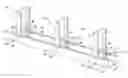
FIG. 1 is an elevated perspective view of a connector clip in accordance with an embodiment of the present invention.
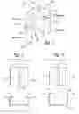
FIG. 2 is a front view of the connector clip shown in FIG. 1, but wherein the connector clip is shown in relation (before engagement) to a sill member (shown in side view) having a standard depth of about 2 inches in accordance with an embodiment of the present invention.
FIG. 3 is a front view of the connector clip shown in FIG. 1, but wherein the connector clip is turned upside down and shown in relation (before engagement) to a sill member (shown in side view) having a standard depth of about 3 inches in accordance with an embodiment of the present invention.
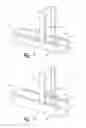
FIG. 4 is an elevated perspective partial view of a wall assembly, wherein the connector clip is shown in relation (engaged and attached) to a sill member having a standard depth of about 2 inches in accordance with an embodiment of the present invention.
FIG. 5 is an elevated perspective partial view of a wall assembly, wherein the connector clip is turned upside down and shown in relation (engaged and attached) to a sill member having a standard depth of about 3 inches in accordance with an embodiment of the present invention.
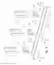
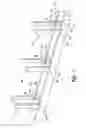
FIG. 6 is an elevated perspective partial exploded view of a wall assembly, wherein the connector clip is turned upside down (flipped over) and shown in relation to a sill member having a standard depth of about 3 inches in accordance with an embodiment of the present invention.
FIG. 7 is an elevated perspective partial (non-exploded) view of the wall assembly shown in FIG. 6.
DETAILED DESCRIPTION OF THE INVENTION
Referring now to the drawings wherein like reference numerals are used to designate like features and, more particularly, to FIGS. 1-7, the present invention in an embodiment is directed to a connector clip 10 in a combination with a sheet-metal wall assembly 12 (best shown in FIGS. 6 and 7). As best shown in FIGS. 4 and 5, the innovative connector clip 10 interconnects (joins together) a horizontally positioned sheet-metal sill member 14 (generally either 2 or 3 inches in depth) to an abutting vertically positioned sheet-metal stud 16 (e.g., a cripple stud). As shown, the sill member 14 has opposing sidewalls 14′ that include confronting and inwardly extending upper sill returns 14″. The connector clip 10 is preferably, but not necessarily, made of sheet-metal and is generally or substantially rigid enough to reduce flexural torsional buckling when the wall assembly 12 is carrying a load.
As best shown in FIGS. 1-3, the connector clip 10 comprises a substantially planar web 18 having a pair of opposing side web flanges 20a, 20b, wherein each side web flange 20a, 22b is substantially flat and perpendicular to the web 18. The web 18 also includes first and second horizontally transverse and confronting open-ended inwardly-directed web slots 18′, 18″ (for receiving the upper sill returns 14″). Similarly, the opposing side web flanges 20a, 20b include first and second horizontally transverse open-ended flange slots 20a′, 20b′ (FIG. 1) aligned and continuous (contiguous) with the first and second web slots 18′, 18″ (also for receiving the upper sill returns 14″).
The first and second flange slots 20a′, 20b′ define respective upper and lower portions 20a-upper, 20a-lower, 20b-upper, 20b-lower of the opposing side web flanges 20a, 20b (FIG. 1). In this configuration, the web slots 18′, 18″ and the flange slots 20a′, 20b′ are able to receive and engage with the upper sill returns 14″ of the sill member 14 (FIGS. 4 and 5) such that substantially the entire outer surface of the of the lower portions 20a-lower, 20b-lower of side web flanges 20a, 20b are in planar contact with the respective opposing sidewalls 14′ of the sill member 14. Moreover, the width of each of the opposing side web flanges 20a, 20b is preferably about the same as the width of each stud 16 (to thereby ensure a snug fit).
As best shown in FIGS. 1-3, the connector clip 10 further comprises a vertically oriented, centrally positioned, and outwardly extending elongated rib 22 (also sometimes referred to as a crimp, ridge or corrugation) that runs parallel to the opposing side web flanges 20a, 20b. In certain preferred embodiments, the rib 22 has a V-shaped cross-sectional profile. The rib 22 generally reduces buckling and twisting throughout the clip 22 when a load is applied on the wall assembly 12. In alternative embodiments, the connector clip includes a plurality of ribs (not shown).
In order to facilitate attachment of the studs 16 to the sill member 14, the connector clip 10 further comprises a plurality of holes 24 penetrating through the web 18 (FIG. 1). A plurality of corresponding fasteners 26 (e.g., sheet-metal screws) fasten and join together the sill member 14 to the stud 16 (FIG. 4-7).
Finally, and in order to facilitate attachment of the connector clip 10 (by flipping or turning upside down) to the stud 16 and to either a 2 inch or 3 inch deep sill member 14, the height of the upper portions 20a-upper, 20b-upper of the side web flanges 20a, 20b is about two thirds the height of the lower portions 20a-lower, 20b-lower of the side web flanges 20a, 20b. Thus, and in this configuration, the height of each of the lower portions 20a-lower, 20b-lower of the side web flanges 20a, 20b is about the same as the depth of the selected 2 or 3 inch sill member 14 (to thereby ensure a snug fit that facilitates attachment prior to secure fastening with the fasteners 26).
While the present invention has been described in the context of the embodiments illustrated and described herein, the invention may be embodied in other specific ways or in other specific forms without departing from its spirit or essential characteristics. Therefore, the described embodiments are to be considered in all respects as illustrative and not restrictive. The scope of the invention is, therefore, indicated by the appended claims rather than by the foregoing description, and all changes that come within the meaning and range of equivalency of the claims are to be embraced within their scope.
Claims
What is claimed is:1. In combination with a sheet-metal wall assembly, a connector clip interconnecting a horizontally positioned sheet-metal sill member to an abutting vertically positioned sheet-metal stud, wherein the sill member has opposing sidewalls that include confronting and inwardly extending upper sill returns, the connector clip comprising:
a substantially planar web having a pair of opposing side web flanges, wherein each side web flange is substantially flat and perpendicular to the web;
first and second horizontally transverse and confronting open-ended inwardly-directed web slots on the web; and
first and second horizontally transverse open-ended flange slots aligned and continuous with the first and second web slots, wherein the first and second flange slots define respective upper and lower portions of the opposing side web flanges, and wherein the web slots and the flange slots are engaged with the upper sill returns of the sill member such that substantially the entire outer surface of the of the lower portions of side web flanges are in planar contact with the respective opposing sidewalls of the sill member.
2. The connector clip of claim 1, further comprising a vertically oriented, centrally positioned, and outwardly extending elongated rib that runs parallel to the opposing side web flanges.
3. The connector clip of claim 2 wherein the elongated rib has a V-shaped cross-sectional profile.
4. The connector clip of claim 1, further comprising a plurality of holes penetrating through the web, and a plurality of corresponding fasteners joining the sill member to the stud through the plurality of holes.
5. The connector clip of claim 1 wherein the height of the upper portions of the side web flanges is about two thirds the height of the lower portions of the side web flanges.
6. The connector clip of claim 1 wherein the width of each of the opposing side web flanges is about the same as the width of the stud.
7. The connector clip of claim 6 wherein the height of each of the lower portions of the side web flanges is about the same as the depth of the sill member.
Images & Drawings included:
Sources:
- United States Patent and Trademark Office - verify current appl. status at the USPTO↗
Recent applications in this class:
- » 20250067041 2025-02-27
MODULAR BUILDING UNITS, AND METHODS OF CONSTRUCTING AND TRANSPORTING SAME - » 20250019958 2025-01-16
SYSTEMS AND MODULAR UNITS FOR BUILDING STRUCTURES - » 20240301676 2024-09-12
MODULARIZED FRAMEWORK STRUCTURE AND UNIT MODULE FOR USE IN THE SAME - » 20240271409 2024-08-15
ELEVATED KNIFE PLATE BRACKET - » 20240247479 2024-07-25
SPACE FRAME - » 20240102273 2024-03-28
OCTAHEDRAL RETICULATED STEREO MODULE FOR THE CONSTRUCTION OF BUILDINGS - » 20240035270 2024-02-01
A CONNECTOR - » 20230392366 2023-12-07
STRUCTURAL MODULAR BUILDING CONNECTOR - » 20230103559 2023-04-06
CONNECTORS FOR A FRAMING SYSTEM - » 20230043888 2023-02-09
Modular building units, and methods of constructing and transporting same