Multiple sealing bars for film wrapping
US20140298755A1
2014-10-09
14/246,814
2014-04-07
✅ Patent granted
US 9,533,781 B2
2017-01-03
-
-
Christopher Harmon
Sam Silverberg
2035-07-08
Abstract:
This invention is directed to multiple sealing bars to seal articles moving on a conveyor 2 inside a sleeve 4 that forms a continuous film tube 5. Retracting conveyors act to collapse the tube between the articles so that the collapsed portion of the tube can be sealed. The synchronization of the sealing bars with the movement of retracting conveyors allows for a continuous motion machine where the products inside the film do not stop.
Applicant:
Interested in similar patents?
Get notified when new applications in this technology area are published.
Classification:
B65B51/26 » CPC main
Devices for, or methods of, sealing or securing package folds or closures; Devices for gathering or twisting wrappers, or necks of bags; Applying or generating heat or pressure or combinations thereof Devices specially adapted for producing transverse or longitudinal seams in webs or tubes
B65B9/10 » CPC main
Enclosing successive articles, or quantities of material, e.g. liquids or semiliquids, in flat, folded, or tubular webs of flexible sheet material; Subdividing filled flexible tubes to form packages Enclosing successive articles, or quantities of material, in preformed tubular webs, or in webs formed into tubes around filling nozzles, e.g. extruded tubular webs
B65B51/30 IPC
Devices for, or methods of, sealing or securing package folds or closures; Devices for gathering or twisting wrappers, or necks of bags; Applying or generating heat or pressure or combinations thereof; Devices specially adapted for producing transverse or longitudinal seams in webs or tubes Devices, e.g. jaws, for applying pressure and heat, e.g. for subdividing filled tubes
B29C65/787 » CPC further
Joining of preformed parts ; Apparatus therefor; Means for handling the parts to be joined, e.g. for making containers or hollow articles, e.g. means for handling sheets, plates, web-like materials, tubular articles, hollow articles or elements to be joined therewith; Means for discharging the joined articles from the joining apparatus characterised by the feeding movement of the parts to be joined; In-line machines, i.e. feeding, joining and discharging are in one production line using conveyor belts or conveyor chains
B29C65/78 IPC
Joining of preformed parts ; Apparatus therefor Means for handling the parts to be joined, e.g. for making containers or hollow articles, e.g. means for handling sheets, plates, web-like materials, tubular articles, hollow articles or elements to be joined therewith; Means for discharging the joined articles from the joining apparatus
B29C65/7894 » CPC further
Joining of preformed parts ; Apparatus therefor; Means for handling the parts to be joined, e.g. for making containers or hollow articles, e.g. means for handling sheets, plates, web-like materials, tubular articles, hollow articles or elements to be joined therewith; Means for discharging the joined articles from the joining apparatus characterised by the feeding movement of the parts to be joined; Means for handling of moving sheets or webs of continuously moving sheets or webs
B29C66/1122 » CPC further
General aspects of processes or apparatus for joining preformed parts; General aspects dealing with the joint area or with the area to be joined; Particular design of joint configurations particular design of the joint cross-sections; Joint cross-sections comprising a single joint-segment, i.e. one of the parts to be joined comprising a single joint-segment in the joint cross-section; Single lapped joints Single lap to lap joints, i.e. overlap joints
B29C66/343 » CPC further
General aspects of processes or apparatus for joining preformed parts; General aspects dealing with the joint area or with the area to be joined Making tension-free or wrinkle-free joints
B29C66/4312 » CPC further
General aspects of processes or apparatus for joining preformed parts; General aspects of joining substantially flat articles, e.g. plates, sheets or web-like materials; Making flat seams in tubular or hollow articles; Joining single elements to substantially flat surfaces; Joining substantially flat articles ; Making flat seams in tubular or hollow articles; Joining a relatively small portion of the surface of said articles; Joining the articles to themselves for making flat seams in tubular or hollow articles, e.g. transversal seams
B29C66/73715 » CPC further
General aspects of processes or apparatus for joining preformed parts characterised by the composition, physical properties or the structure of the material of the parts to be joined; Joining with non-plastics material characterised by the intensive physical properties of the material of the parts to be joined, by the optical properties of the material of the parts to be joined, by the extensive physical properties of the parts to be joined, by the state of the material of the parts to be joined or by the material of the parts to be joined being a thermoplastic or a thermoset characterised by the state of the material of the parts to be joined oriented or heat-shrinkable heat-shrinkable
B29C66/81465 » CPC further
General aspects of processes or apparatus for joining preformed parts; General aspects of machine operations or constructions and parts thereof; General aspects of the pressing elements, i.e. the elements applying pressure on the parts to be joined in the area to be joined, e.g. the welding jaws or clamps characterised by the design of the pressing elements, e.g. of the welding jaws or clamps characterised by the constructional aspects of the pressing elements, e.g. of the welding jaws or clamps comprising a plurality of single pressing elements, e.g. a plurality of sonotrodes, or comprising a plurality of single counter-pressing elements, e.g. a plurality of anvils, said plurality of said single elements being suitable for making a single joint one placed behind the other in a single row in the feed direction
B29C66/83543 » CPC further
General aspects of processes or apparatus for joining preformed parts; General aspects of machine operations or constructions and parts thereof characterised by the movement of the joining or pressing tools moving with the parts to be joined; Jaws mounted on rollers, cylinders, drums, bands, belts or chains; Flying jaws flying jaws, e.g. jaws mounted on crank mechanisms or following a hand over hand movement cooperating flying jaws
B29C66/849 » CPC further
General aspects of processes or apparatus for joining preformed parts; General aspects of machine operations or constructions and parts thereof; Specific machine types or machines suitable for specific applications Packaging machines
B29C66/8432 » CPC further
General aspects of processes or apparatus for joining preformed parts; General aspects of machine operations or constructions and parts thereof; Specific machine types or machines suitable for specific applications; Machines for making separate joints at the same time in different planes; Machines for making separate joints at the same time mounted in parallel or in series Machines for making separate joints at the same time mounted in parallel or in series
B29C65/74 » CPC further
Joining of preformed parts ; Apparatus therefor by welding and severing, or by joining and severing, the severing being performed in the area to be joined, next to the area to be joined, in the joint area or next to the joint area
B65B61/06 » CPC further
Auxiliary devices, not otherwise provided for, for operating on sheets, blanks, webs, binding material, containers or packages for severing webs, or for separating joined packages by cutting
B29C65/00 IPC
Joining of preformed parts ; Apparatus therefor
B29C65/02 » CPC further
Joining of preformed parts ; Apparatus therefor by heating, with or without pressure
B65B51/303 » CPC further
Devices for, or methods of, sealing or securing package folds or closures; Devices for gathering or twisting wrappers, or necks of bags; Applying or generating heat or pressure or combinations thereof; Devices specially adapted for producing transverse or longitudinal seams in webs or tubes; Devices, e.g. jaws, for applying pressure and heat, e.g. for subdividing filled tubes reciprocating along only one axis
Description
FIELD OF THE INVENTION
This invention is related to using multiple sealing bars on a film wrapping machine. The film wrapping machine can include a heat tunnel that shrinks the film around an article.
BACKGROUND OF THE INVENTION
The use of a single sealing bar on film wrapping machine is well known in the art. In order to seal and separate the articles in the tube, a section of the tube between the articles needs to collapse so that the sealing bar can pinch and seal the collapsed tube while the articles are moving on a conveyor. During the sealing process the section of the collapsed tube is separated thereby forming an article inside a tube that is sealed at each end. To collapse the tube a conveyor needs to be slowed to increase the slack in the tube. This reduces the productivity of the machine.
BRIEF DESCRIPTION OF THE DRAWING
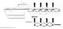
FIGS. 1-3 shows the using multiple sealing bars with retractable conveyors
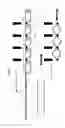
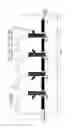
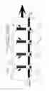
FIGS. 4-6 shows a detailed view how the sealing bars and the retractable conveyors operate.
DETAILED DESCRIPTION OF THE INVENTION
This invention addresses the need in the art for a faster machine. Faster productivity is accomplished by using multiple sealing bars. Multiple sealing bars have not been used in the prior art. FIGS. 1-3 shows multiple seal bars SB-1 to SB-4 an articles or bundles of articles 1 moving on a conveyor 2 inside a sleeve 4 that forms a continuous film tube 5. FIGS. 4, 5 and 6 show a detailed view of the movement of the sealing bars, retracting conveyors and the carriage as shown in FIGS. 1 and 2. FIG. 4 shows a continuous motion machine where the products inside the film do not stop. The machine and product is moving at a continuous speed S. The sealing bars SB-1, SB-2, SB-3 and S-B4 and the conveyors D1, D2 and D3 between the sealing bars are mounted on a carriage 6. When the first product passes SB4 shown as position E, the carriage starts moving at approximately or slightly less than the speed S. FIG. 5 shows collapsing the film tube by decreasing the tension on the film tube by contracting the length of each conveyor between the sealing bars D1, D2 and D3. The conveyors move at a speed approximately or slight less than the speed of the machine and products. The contracted length of each conveyor is approximately the same. While the length of the conveyor is contracted the sealing bars follow the same motion staying about equal distance between the ends of the shorter conveyor. While the conveyor between the sealing bars are contracting, conveyors C and E are expanding to insure that the gaps between conveyors C and D1 and D3 and E are at the desired spacing. The contraction of the conveyors is completed about the same time the sealing bars is closing on the film tube. When the sealing bar is closed the conveyors maintain their contracted length.
FIG. 5 shows sealing SB1 and SB2 following conveyor D1 in the machine direction. Like wise SB3 and SB4 follows the movement of conveyor D2 and D3 to position themselves equidistant between the shorter conveyers. When the sealing bars start to close and the conveyor lengths contract, conveyor C and E moves from the position shown in FIG. 4 to the position shown in FIG. 5. Likewise Conveyor E slows down when move in the closed. During the entire process conveyor C moves at approximately same speed S or slightly less. Conveyor E will slow down when the sealing bars close and will accelerate when sealing Bar SB4 opens. The sealing bar cuts the film tube and seals each end.
FIG. 6 shows that after sealing, the carriage with the sealing bars and the retracted conveyors move back to their original position. The speed of the sealing bars has to be sufficient to insure that they are located between the retracted conveyors.
Claims
1. A process for using multiple sealing bars for sealing products in a tube moving on a conveyor comprising:
placing articles on a conveyor
transporting the articles into a film tube at a predetermined speed
providing a carriage having multiple movable sealing bars spaced in the direction of movement of the articles and conveyors between the sealing bars wherein the length of the conveyors can contract and expand,
sensing when an article in the tube passes the sealing bar located furthest down stream
moving the carriage in machine direction at about or slightly less then the predetermined speed in response to the sensing,
contracting the length of the conveyors between the sealing bar to collapse the film tube between articles while positioning the sealing bars over the collapsed film between the articles,
sealing the collapsed film, and
retracting the carriage to the original position while the sealing bars and the conveyors between the sealing bars return to their approximate starting position.
2. A process according to claim 1 wherein a retractable conveyor is located down stream of the last sealing bar will slow down when the sealing bar closes and will accelerate when the sealing bar opens.
3. A process according to claim 2 wherein there are 4 movable seal bars.
4. An apparatus for using multiple sealing bars for sealing articles in a film tube comprising,
means for placing articles on a conveyor,
means for transporting the articles into a film tube
means for carrying movable sealing bars spaced in the direction of the of the movement of the articles and retractable conveyors between the sealing bars for moving the film tube,
means for collapsing the film tube between the articles, and
means for sealing and cutting the collapsed film
5. An apparatus according to claim 4 wherein the means for carrying is a carriage that moves in the machine direction.
6. An apparatus according to claim 5 wherein the sealing bars and the retractable conveyors are mounted on the carriage
7. An apparatus according to claim 5 wherein the means for collapsing includes means for retracting the conveyors between the sealing bars to collapse the tube film.
8. An apparatus according to claim 7 wherein the sealing bars move to a location between the retracted conveyors to cut and seal the tube film.
9. An apparatus according to claim 1 including a retractable conveyor before the first sealing bar and a retractable conveyor after the last sealing bar.
10. An apparatus according to claim 8 including means for moving the carriage forward when an article passes the sealing bar located furthest down stream.
11. An apparatus according to claim 10 including means for moving the carriage to about its original position after the tube film has been cut and sealed
12. A process for using multiple sealing bars for sealing products in a tube moving on a conveyor comprising:
placing articles on a conveyor
transporting the articles into a film tube at a predetermined speed
providing a carriage having multiple movable sealing bars spaced in the direction of movement of the articles and conveyors between the sealing bars wherein the length of the conveyors can contract and expand,
moving the carriage in machine direction at about or slightly less then the predetermined speed,
contracting the length of the conveyors between the sealing bar to collapse the film tube, between articles while positioning the sealing bars over the collapsed film between the articles,
sealing the collapsed film, and
retracting the carriage to the original position while the sealing bars and the conveyors between the sealing bars return to their approximate starting position.
Images & Drawings included:


Sources:
- United States Patent and Trademark Office - verify current appl. status at the USPTO↗
Recent applications in this class:
- » 20250074646 2025-03-06
METHOD OF PACKAGING NICOTINE POUCH AND NICOTINE POUCH MANUFACTURED USING THE SAME - » 20240425216 2024-12-26
SEALING DEVICE FOR A PACKAGING MACHINE, PACKAGING MACHINE HAVING A SEALING DEVICE AND METHOD OF OPERATING A SEALING DEVICE - » 20240278950 2024-08-22
TRANSVERSE SEALING UNIT FOR PRODUCING TRANSVERSE SEALING SEAMS IN A TUBULAR BAG MACHINE - » 20220289414 2022-09-15
Triple center sealing device in pillow packaging machine - » 20210039818 2021-02-11
Fill-packaging method for plural rows and fill-packaging machine for plural rows - » 20190152638 2019-05-23
Packaging machine - » 20170313459 2017-11-02
Device, in particular for closing a head region of a foodstuffs container made of a laminate having an edge region which is skived and partially folded over itself - » 20170275033 2017-09-28
Idler roller - » 20170174377 2017-06-22
Magnetically operated sealing bar assembly for packaging machines - » 20130263556 2013-10-10
Folding unit for forming sealed packages of pourable food products