Optimizing acoustic efficiency of a sonic filter or separator
US20140301902A1
2014-10-09
13/983,398
2012-02-06
✅ Patent granted
US 9,833,763 B2
2017-12-05
WO; PCT/US2012/023960; 20120206
WO; WO2012/154237; 20121115
Regina M Yoo
Ware, Fressola, Maguire & Barber LLP
2032-06-06
Abstract:
Apparatus features a container and a transducer. The container is made of a selected material and has a container wall with a selected thickness, and configured to hold a fluid therein. The transducer is configured on the outside of the container wall, and is also configured to provide a standing wave into the fluid. The selected thickness and material of the container wall is chosen to ensure about a ½ wavelength of a desired frequency exists within the container wall, so as to substantially reduce back reflections toward the transducer due to any mismatch in acoustic impedance at the interface between the container wall and the fluid, and so as to substantially maximize the amount of energy delivered to the fluid, thus improving the operating efficiency of the apparatus.
Inventors:
- Mark R. Fernald 70 🇺🇸 Enfield, CT, United States
- Timothy J. Bailey 42 🇺🇸 Longmeadow, MA, United States
Assignee:
- CIDRA CORPORATE SERVICES INC. 88 🇺🇸 Wallingford, CT, United States
Applicant:
Interested in similar patents?
Get notified when new applications in this technology area are published.
Classification:
B01J2219/0877 » CPC further
Chemical, physical or physico-chemical processes in general; Their relevant apparatus; Processes employing the direct application of electric or wave energy, or particle radiation; Apparatus therefor; Materials to be treated Liquid
B01J19/10 » CPC main
Chemical, physical or physico-chemical processes in general; Their relevant apparatus; Processes employing the direct application of electric or wave energy, or particle radiation; Apparatus therefor employing sonic or ultrasonic vibrations
G01F23/2961 » CPC further
Indicating or measuring liquid level or level of fluent solid material, e.g. indicating in terms of volume or indicating by means of an alarm by measuring physical variables, other than linear dimensions, pressure or weight, dependent on the level to be measured, e.g. by difference of heat transfer of steam or water by measuring the variations of parameters of electromagnetic or acoustic waves applied directly to the liquid or fluent solid material; Acoustic waves for discrete levels
G01F23/2967 » CPC further
Indicating or measuring liquid level or level of fluent solid material, e.g. indicating in terms of volume or indicating by means of an alarm by measuring physical variables, other than linear dimensions, pressure or weight, dependent on the level to be measured, e.g. by difference of heat transfer of steam or water by measuring the variations of parameters of electromagnetic or acoustic waves applied directly to the liquid or fluent solid material; Acoustic waves making use of acoustical resonance or standing waves for discrete levels
B03D1/028 » CPC further
Flotation; Froth-flotation processes Control and monitoring of flotation processes; computer models therefor
G01F23/296 IPC
Indicating or measuring liquid level or level of fluent solid material, e.g. indicating in terms of volume or indicating by means of an alarm by measuring physical variables, other than linear dimensions, pressure or weight, dependent on the level to be measured, e.g. by difference of heat transfer of steam or water by measuring the variations of parameters of electromagnetic or acoustic waves applied directly to the liquid or fluent solid material Acoustic waves
B03D1/02 IPC
Flotation Froth-flotation processes
Description
CROSS-REFERENCE TO RELATED APPLICATIONS
This application claims benefit to provisional patent application Ser. No. 61/439,540 (CCS-0041), filed 4 Feb. 2011, which is incorporated by reference in their entirety.
BACKGROUND OF THE INVENTION
1. Field of Invention
The present invention relates to a technique for providing a standing wave into fluid in a container.
2. Description of Related Art
Sonic filters and separators based upon standing wave agglomeration are known and have been demonstrated. The efficiency of such filters is determined by the amount of electrical energy required to obtain a specified level of separation.
Typically, a standing wave may be set up in a fluid by acoustically driving the fluid by situating an appropriate transducer to the outside of the container containing the fluid. However, one problem with this type of configuration is that the interface between the fluid and the container wall causes back reflections (toward the transducer) due to the mismatch in acoustic impedance between the container wall and the fluid. This reflection results in less acoustic energy being imparted to the fluid. Because of this, the maximum amount of energy is not delivered to the fluid, thus reducing the operating efficiency thereof.
There is a need to improve the efficiency of such filters, e.g., by lowering the required acoustic drive power.
The is also a need in the industry to improve the maximum amount of energy delivered to the fluid, thus improving the operating efficiency of these types of devices and processes.
SUMMARY OF THE INVENTION
The present invention provides for a proper selection of the thickness and/or material to ensure that a ½ wavelength of a desired frequency exists within the container wall. Under these conditions, a maximum amount of energy is delivered to the fluid, thus improving the operating efficiency.
The present invention also provides an improved excitation method to improve the efficiency by lowering the required acoustic drive power.
According to some embodiments, the present invention may take the form of apparatus featuring a container and a transducer. The container has a container wall characterized by at least one parameter, including being made of a selected type of material or having a selected thickness, and is configured to hold a fluid therein. The transducer is configured on the outside of the container wall, and is also configured to provide a standing wave into the fluid. The at least one parameter of the container wall is selected to ensure about a ½ wavelength of a desired frequency exists within the container wall, so as to substantially reduce back reflections toward the transducer due to any mismatch in acoustic impedance at the interface between the container wall and the fluid, and so as to substantially maximize the amount of energy delivered to the fluid, thus improving the operating efficiency of the apparatus.
According to some embodiments, the present invention may also include some combination of the following features:
The at least one parameter may include a combination of the selected material and the selected thickness of the container wall.
The container wall may be a steel plate
The container wall may have a thickness of about ¾″.
The transducer may be configured to provide the standing wave into the fluid with a sound speed in the steel plate of about 5,740 meters/sec, so as to produce a first ½ wave resonance at about 150.7 KHz, a second resonance (first full wave) at about 301.4 KHz, and a third resonance at about 452.1 KHz.
The apparatus may include, or take the form of, a sonic filter or separator.
BRIEF DESCRIPTION OF THE DRAWING
The drawing includes FIG. 1, which is not necessarily drawn to scale, and which is a diagram showing apparatus according to some embodiments of the present invention.
DETAILED DESCRIPTION OF BEST MODE OF THE INVENTION
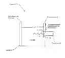
By way of example, FIG. 1 shows the present invention in the form of apparatus generally indicated as 10 featuring a container 12 in combination with a transducer 14. The container 12 has a container wall 16 characterized by at least one parameter, including being made of a selected type of material or having a selected thickness T. The container 12 is configured to hold a fluid F therein. The transducer 14 is configured on the outside of the container wall 16, and is also configured to provide a standing wave W into the fluid F.
The at least one parameter of the container wall 16 is selected to ensure about a ½ wavelength (½λ) of a desired frequency exists within the container wall 16, so as to substantially reduce back reflections toward the transducer 14 due to any mismatch in acoustic impedance at the interface I between the container wall 16 and the fluid F, and so as to substantially maximize the amount of energy delivered to the fluid F, thus improving the operating efficiency of the apparatus 10.
According to some embodiments of the present invention, the at least one parameter may be a combination of the selected material and the selected thickness T of the container wall 16.
According to some embodiments of the present invention, the container wall 16 may be a steel plate and/or the container wall 16 may have a thickness of about ¾″.
According to some embodiments of the present invention, the transducer 14 may be configured to provide the standing wave W into the fluid F with a sound speed in the steel plate of about 5,740 meters/sec, so as to produce a first ½ wave resonance at about 150.7 KHz, a second resonance (first full wave) at about 301.4 KHz, and a third resonance at about 452.1 KHz.
According to some embodiments of the present invention, the apparatus 10 may be, or form part of, a sonic filter or separator.
Containers like element 12 are known in the art, and the scope of the invention is not intended to be limited to any particular type or kind thereof either now known or later developed in the future. By way of example, the container may include, or take the form of, a flotation tank, a column, a drum, a tube, a vat, etc.
Transducers like element 14 are known in the art, and the scope of the invention is not intended to be limited to any particular type or kind thereof either now known or later developed in the future.
The scope of the invention is not intended to be limited to the calculated values of the at least one parameters set forth above by way of example. Embodiments are envisioned using other types or kinds of selected materials either now known or later developed in the future, other types or kinds of selected container wall thicknesses either now known or later developed in the future, as well as other types or kinds of combinations of selected materials and selected container wall thicknesses either now known or later developed in the future.
Applications Re Other Industrial Processes
By way of example, in known industrial processes sound passing through a fluid, mixture, gas/vapor of a process flow, e.g. in a pipe or container, may be sensed and used to determine parameters related to the fluid, mixture, gas/vapor. The sound may be generated by equipment operating either in association with the process flow or in close proximity to the process flow. The sound generated by equipment operating in association with the process flow may include sound in the form of a standing wave generated by such an appropriate transducer or other known sound generating device that is coupled or connected, e.g., to the outside of a container wall of a container, a pipe wall of a pipe, a tank wall of a tank, etc. See, e.g., the technology disclosed in PCT patent application serial no. PCT/US/27731, filed 9 March 2011 (Atty docket no. 712-2.338-1 (CCS 33, 35, 40, 45-49)), entitled “Method and apparatus for determining GVF (gas volume fraction) for aerated fluids and liquids in flotation tanks, columns, drums, tubes, vats,” which has been assigned to the assignee of the present application, and which is hereby incorporated by reference in its entirety.
Further, the present invention also may be used in, or form part of, or used in conjunction with, SONAR-based entrained air meter and metering technology known in the art taking the form of a SONAR-based meter disclosed, e.g., in whole or in part in U.S. Pat. Nos. 7,165,464; 7,134,320; 7,363,800; 7,367,240; and 7,343,820.
Furthermore, the present invention may also be used in, or form part of, or used in conjunction with, industrial processes like a mineral extraction processing system for extracting minerals from ore either now known or later developed in the future, including any mineral process, such as those related to processing substances or compounds that result from inorganic processes of nature and/or that are mined from the ground, as well as including either other extraction processing systems or other industrial processes, where the sorting, or classification, of product by size is critical to overall industrial process performance.
The Scope of the Invention
While the invention has been described with reference to an exemplary embodiment, it will be understood by those skilled in the art that various changes may be made and equivalents may be substituted for elements thereof without departing from the scope of the invention. In addition, may modifications may be made to adapt a particular situation or material to the teachings of the invention without departing from the essential scope thereof. Therefore, it is intended that the invention not be limited to the particular embodiment(s) disclosed herein as the best mode contemplated for carrying out this invention.
Claims
What is claimed is:1. Apparatus comprising:
a container having a container wall characterized by at least one parameter, including being made of a selected type of material or having a selected thickness, the container being configured to hold a fluid therein;
a transducer configured on the outside of the container wall, and also configured to provide a standing wave into the fluid;
the at least one parameter of the container wall being selected to ensure about a ½ wavelength of a desired frequency exists within the container wall, so as to substantially reduce back reflections toward the transducer due to any mismatch in acoustic impedance at the interface between the container wall and the fluid, and so as to substantially maximize the amount of energy delivered to the fluid, thus improving the operating efficiency of the apparatus.
2. Apparatus according to claim 1, wherein the at least one parameter is a combination of the selected material and the selected thickness of the container wall.
3. Apparatus according to claim 2, wherein the container wall is a steel plate
4. Apparatus according to claim 2, wherein the selected thickness is about ¾″.
5. Apparatus according to claim 2, wherein the container wall is a steel plate having a thickness of about ¾″.
6. Apparatus according to claim 5, wherein the transducer is configured to provide the standing wave into the fluid with a sound speed in the steel plate of about 5,740 meters/sec, so as to produce a first ½ wave resonance at about 150.7 KHz, a second resonance (first full wave) at about 301.4 KHz, a third resonance is produced at about 452.1 KHz, etc.
7. Apparatus according to claim 1, wherein the apparatus is a sonic filter or separator.
8. Apparatus comprising:
a container having a container wall being made of a selected material and having a selected thickness, and being configured to hold a fluid therein;
a transducer configured on the outside of the container wall, and also configured to provide a standing wave into the fluid;
the selected material and the selected thickness of the container wall being chosen to ensure about a ½ wavelength of a desired frequency exists within the container wall,
so as to substantially reduce back reflections toward the transducer due to any mismatch in acoustic impedance at the interface between the container wall and the fluid, and so as to substantially maximize the amount of energy delivered to the fluid, thus improving the operating efficiency of the apparatus.
9. Apparatus according to claim 8, wherein the container wall is a steel plate having a thickness of about ¾″.
10. Apparatus according to claim 9, wherein the transducer is configured to provide the standing wave into the fluid with a sound speed in the steel plate of about 5,740 meters/sec, so as to produce a first ½ wave resonance at about 150.7 KHz, a second resonance (first full wave) at about 301.4 KHz, a third resonance is produced at about 452.1 KHz, etc.
12. Apparatus according to claim 8, wherein the apparatus is a sonic filter or separator.
Images & Drawings included:
Sources:
- United States Patent and Trademark Office - verify current appl. status at the USPTO↗
Recent applications in this class:
- » 20250222426 2025-07-10
ACOUSTIC REACTOR - » 20240424469 2024-12-26
SYSTEM AND METHOD FOR GENERATION OF NANOPARTICLES USING ULTRASONIC ENERGY - » 20240278205 2024-08-22
LARGE-VOLUME ULTRASONIC TUBULAR REACTOR - » 20240189793 2024-06-13
DEVICE AND METHOD FOR INFLUENCING THE FLOW OF A FLOWABLE MEDIUM THROUGH ENERGY INTENSITY ZONES - » 20230149884 2023-05-18
Reactor System and Method for Producing and/or Treating Particles - » 20230101974 2023-03-30
Apparatus and method for enhancing yield and transfer rate of a packed bed - » 20230071935 2023-03-09
MICROPLATE CYCLING THERMO SONICATOR WITH PROGRAMMABLE ULTRASOUND, HEATING, AND COOLING FOR MULTI-ANALYTICAL APPLICATIONS - » 20230050109 2023-02-16
METHOD AND SYSTEM FOR CONTROLLING AN ULTRASOUND GENERATOR OF A MACHINE TOOL FOR MACHINING A WORKPIECE - » 20220410115 2022-12-29
SYSTEMS AND METHODS FOR DISPERSION OF DRY POWDERS - » 20220387960 2022-12-08
Post-processing apparatus
Recent applications for this Assignee:
- » 20240150643 2024-05-09
Smart proppant technology for fracking and well production performance monitoring - » 20230332040 2023-10-19
Smart proppant technology for fracking and well production performance monitoring - » 20220145168 2022-05-12
Smart proppant technology for fracking and well production performance monitoring - » 20220034844 2022-02-03
Method and apparatus for providing real time air measurement applications in wet concrete using dual frequency techniques - » 20220023876 2022-01-27
Reactor system for separation and enrichment of minerals from a slurry containing minerals and other materials - » 20210382505 2021-12-09
Method and apparatus for using velocity profile measurements in recovering bitumen from a coarse tailings line - » 20210172909 2021-06-10
Method and apparatus for determining GVF—gas volume fraction—for aerated fluids and liquids in flotation tanks, columns, drums, tubes, vats - » 20210071283 2021-03-11
Opportunities for recovery augmentation process as applied to molybdenum production - » 20200124570 2020-04-23
Method and apparatus for providing real time air measurement applications in wet concrete using dual frequency techniques - » 20200070074 2020-03-05
Polymer coating for selective separation of hydrophobic particles in aqueous slurry