Counterweight structure of a traffic cone
US20140305366A1
2014-10-16
13/862,569
2013-04-15
✅ Patent granted
US 9,120,259 B2
2015-09-01
-
-
R. A. Smith
2034-02-05
Abstract:
A counterweight structure of a traffic cone contains a base pre-molded and placed into a conical mold so as to injection mold a conical post. The base includes a groove for connecting with the conical post, a connecting piece mounted around the groove, and a plurality of retaining tabs arranged on the connecting piece. Each retaining tab has a neck portion coupled with the groove, and between any two abutting retaining tabs is defined an elongated hole communicating with the connecting piece, two orifices are arranged on two sides of the neck of the each retaining tab and communicate with the connecting piece, such that when the conical post is injection molded to cover the base, the connecting piece, the plurality of retaining tabs and a plurality of retaining tabs horizontally retain together, and a plurality of orifices are provided to vertically connect the conical post and the base together.
Assignee:
- JING NAN TRAFFIC ENGINEERING CO., LTD. 3 🇹🇼 Changhua County, Taiwan
Applicant:
Interested in similar patents?
Get notified when new applications in this technology area are published.
Classification:
B29C45/14819 » CPC further
Injection moulding, i.e. forcing the required volume of moulding material through a nozzle into a closed mould; Apparatus therefor incorporating preformed parts or layers, e.g. injection moulding around inserts or for coating articles the inserts being completely encapsulated
B29C45/1418 » CPC main
Injection moulding, i.e. forcing the required volume of moulding material through a nozzle into a closed mould; Apparatus therefor incorporating preformed parts or layers, e.g. injection moulding around inserts or for coating articles the inserts being deformed or preformed, e.g. by the injection pressure
B29C45/14311 » CPC further
Injection moulding, i.e. forcing the required volume of moulding material through a nozzle into a closed mould; Apparatus therefor incorporating preformed parts or layers, e.g. injection moulding around inserts or for coating articles using means for bonding the coating to the articles
B29C45/14344 » CPC further
Injection moulding, i.e. forcing the required volume of moulding material through a nozzle into a closed mould; Apparatus therefor incorporating preformed parts or layers, e.g. injection moulding around inserts or for coating articles; Coating a portion of the article, e.g. the edge of the article Moulding in or through a hole in the article, e.g. outsert moulding
B29L2022/00 » CPC further
Hollow articles
B29C45/14 IPC
Injection moulding, i.e. forcing the required volume of moulding material through a nozzle into a closed mould; Apparatus therefor incorporating preformed parts or layers, e.g. injection moulding around inserts or for coating articles
Description
FIELD OF THE INVENTION
The present invention relates to a counterweight structure, and more particularly to a counterweight structure of a traffic cone.
BACKGROUND OF THE INVENTION
Conventional traffic cone contains a base and a conical post connected with the base by ways of dovetail holes, i.e., a plurality of dovetail holes are used to connect the conical post with the base. However such a connection is applied to horizontally connect the conical post with the base, so the conical post cannot connect with the base vertically, thus reducing a connecting effect.
The present invention has arisen to mitigate and/or obviate the afore-described disadvantages.
SUMMARY OF THE INVENTION
The primary object of the present invention is to provide a counterweight structure of a traffic cone in which the conical post is connected with the base securely.
To obtain the above objectives, a counterweight structure of a traffic cone provided by the present invention contains:
-
- a base pre-molded and placed into a conical mold so as to further injection mold a conical post, wherein
- the base includes a groove defined around a central portion thereof so as to connect with the conical post, a connecting piece mounted around an outer peripheral side of the groove, and a plurality of retaining tabs arranged on a top surface and a bottom surface of the connecting piece and spaced apart from each other, each retaining tab has a neck portion coupled with the groove, and between any two abutting retaining tabs is defined an elongated hole, two orifices are arranged on two sides of the neck of the each retaining tab and are in communication with the connecting piece, such that when the conical post is injection molded to cover the base, the connecting piece, the plurality of retaining tabs and a plurality of retaining tabs horizontally retain together, and a plurality of orifices are provided to vertically connect the conical post and the base together.
The foregoing, as well as additional objects, features and advantages of the invention will be more readily apparent from the following detailed description, which proceeds with reference to the accompanying drawings.
BRIEF DESCRIPTION OF THE DRAWINGS
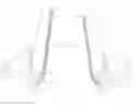
FIG. 1 is a perspective view showing the assembly of a traffic cone according to a preferred embodiment of the present invention.
FIG. 2 is another perspective view showing the assembly of the traffic cone according to the preferred embodiment of the present invention.
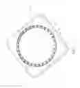
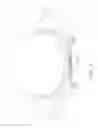
FIG. 3 is a cross-sectional perspective view showing a part of the traffic cone according to the preferred embodiment of the present invention.
FIG. 4 is another cross-sectional perspective view showing a part of the traffic cone according to the preferred embodiment of the present invention.
FIG 5 is also another cross-sectional perspective view showing a part of the traffic cone according to the preferred embodiment of the present invention.
DETAILED DESCRIPTION OF THE PREFERRED EMBODIMENTS
FIG. 1 is a perspective view showing the assembly of a traffic cone according to a preferred embodiment of the present invention. FIG. 2 is another perspective view showing the assembly of the traffic cone according to the preferred embodiment of the present invention. FIG. 3 is a cross-sectional perspective view showing a part of the traffic cone according to the preferred embodiment of the present invention. FIG. 4 is another cross-sectional perspective view showing a part of the traffic cone according to the preferred embodiment of the present invention. FIG. 5 is also another cross-sectional perspective view showing a part of the traffic cone according to the preferred embodiment of the present invention. With reference to FIGS. 1-5, a traffic cone according to the preferred embodiment of the present invention comprises a base 10 pre-molded and placed into a conical mold so as to further injection mold a conical post 20, wherein
-
- the base 10 includes a counterweight block formed by a mold, a groove 11 defined around a central portion thereof so as to connect with the conical post 20, a connecting piece 12 formed around an outer peripheral side of the groove 11, and a plurality of retaining tabs 13 arranged on a top surface and a bottom surface of the connecting piece 12 and spaced apart from each other; each retaining tab 13 is oblong and has a neck portion 14 coupled with the groove 11, and among the each neck portion 14, each retaining tab 13, and the groove 11 is formed a decorative arcuation, and between any two abutting retaining tabs 13 is defined an elongated hole 15 which vertically communicates with the connecting piece 12, two orifices 16 are arranged on two sides of the neck 14 of the each retaining tab 13 and are in communication with the connecting piece 12 and are used to vertically connect the conical post 20 and the base 10 together.
Thereby, in an injection molding process of the conical post 20, the base 10 is placed into a movable mold holder and is connected with a module block of the movable mold holder, and then the movable mold holder is moved to a fixed mold so as to close die, thereafter the conical post 20 is injection molded from good liquidity material. After the conical post 20 is injection molded, it is coupled with the base 10 by communicating the elongated hole 15 and the two orifices 16 with the connecting piece 12, and the each retaining tab 13 and the neck portion 14 connect with the connecting piece 12, such that the conical post 20 is connected with the base 10 securely. In addition, a shape of the each retaining tab 13 and the neck portion 14 enhances an aesthetics appearance of the traffic cone.
Also, the connecting piece 12 and the each retaining tab 13 of the base 10 arcuately extend upward so that a coupling portion of the conical post 20 moves to a connection face of the conical post 20 and the base 10, thus enhancing aesthetics appearance and lowering production material.
While the preferred embodiments of the invention have been set forth for the purpose of disclosure, modifications of the disclosed embodiments of the invention as well as other embodiments thereof may occur to those skilled in the art. Accordingly, the appended claims are intended to cover all embodiments which do not depart from the spirit and scope of the invention.
Claims
What is claimed is:1. A traffic cone comprising: a base pre-molded and placed into a conical mold so as to further injection mold a conical post, wherein
the base includes a groove defined around a central portion thereof so as to connect with the conical post, a connecting piece mounted around an outer peripheral side of the groove, and a plurality of retaining tabs arranged on a top surface and a bottom surface of the connecting piece and spaced apart from each other, each retaining tab has a neck portion coupled with the groove, and between any two abutting retaining tabs is defined an elongated hole, two orifices are arranged on two sides of the neck of the each retaining tab and are in communication with the connecting piece, such that when the conical post is injection molded to cover the base, the connecting piece, the plurality of retaining tabs and a plurality of retaining tabs horizontally retain together, and a plurality of orifices are provided to vertically connect the conical post and the base together.
2. The traffic cone as claimed in claim 1, wherein the each retaining tab is oblong.
3. The traffic cone as claimed in claim 1, wherein the elongated hole vertically communicates with the connecting piece.
4. The traffic cone as claimed in claim 1, wherein and among the each neck portion, each retaining tab, and the groove is formed a decorative arcuation.
5. The traffic cone as claimed in claim 1, wherein the connecting piece and the each retaining tab of the base arcuately extend upward so that a coupling portion of the conical post moves to a connection face of the conical post and the base.
Images & Drawings included:


Sources:
- United States Patent and Trademark Office - verify current appl. status at the USPTO↗
Similar patent applications:
- » 11682444
Traffic cone counterweight structure
Recent applications in this class:
- » 20250249628 2025-08-07
Method for Forming a Composite Component Having a Surface Projection - » 20250010528 2025-01-09
METHOD FOR MOLDING COMPOSITE COMPONENT - » 20230415389 2023-12-28
METHOD FOR PRODUCING A FIBROUS COMPOSITE MATERIAL COMPONENT - » 20230191670 2023-06-22
SYSTEM FOR PRODUCING AT LEAST ONE THREE-DIMENSIONAL ELEMENT ON AN EXTERNAL PART ELEMENT OF A TIMEPIECE - » 20230054242 2023-02-23
Method for manufacturing composite molded article and composite molded article - » 20220297360 2022-09-22
TRAILING ARM MANUFACTURING METHOD - » 20220242018 2022-08-04
Articles Including Panels and Molded Structures and Methods of Making Same - » 20220219359 2022-07-14
Method for producing floorboard for quick sideslip installation - » 20220024088 2022-01-27
Board and method of producing the same - » 20210094208 2021-04-01
PROCESS FOR PRODUCING A COMPOSITE COMPONENT
Recent applications for this Assignee:
- » 20130174775 2013-07-11
Structure of traffic cone - » 11682444 2008-03-04
Traffic cone counterweight structure