Magnetic interface circuit having a 3-wire common mode choke
US20140306781A1
2014-10-16
14/250,638
2014-04-11
✅ Patent granted
US 9,246,464 B2
2016-01-26
-
-
Benny Lee | Rakesh Patel
Ming Chieh Chang | Wei Te Chung
2034-04-11
Abstract:
A magnetic interface circuit for interfacing between a cable side and a circuit side of a networking communication channel. The magnetic interface circuit includes a transformer and a 3-wire common mode choke (CMC). The transformer has a first winding connected to the cable side of the channel and a second winding connected to the circuit side of the channel. Each of the first and second windings has two output ports. The 3-wire CMC has a center winding and two outer windings respectively connected to the output ports of the first or second winding. The center winding has two opposite ends both used for connecting to ground.
Assignee:
- HON HAI PRECISION INDUSTRY CO., LTD. 10,014 🇹🇼 New Taipei, Taiwan
Applicant:
Interested in similar patents?
Get notified when new applications in this technology area are published.
Classification:
H03H7/0115 » CPC main
Multiple-port networks comprising only passive electrical elements as network components; Frequency selective two-port networks comprising only inductors and capacitors
H03H7/01 IPC
Multiple-port networks comprising only passive electrical elements as network components Frequency selective two-port networks
H03H7/427 » CPC further
Multiple-port networks comprising only passive electrical elements as network components; Balance/unbalance networks; Balance-balance networks Common-mode filters
H03H7/09 » CPC further
Multiple-port networks comprising only passive electrical elements as network components; Frequency selective two-port networks Filters comprising mutual inductance
H03H7/42 IPC
Multiple-port networks comprising only passive electrical elements as network components Balance/unbalance networks
Description
BACKGROUND OF THE INVENTION
1. Field of the Invention
The present invention relates to a magnetic interface circuit used for a modular jack connected between a network cable and a circuit board.
2. Description of Related Art
U.S. Pat. No. 7,123,117, issued to Chen et al. on Oct. 17, 2006, discloses a magnetic interface circuit for interfacing between a cable side and a circuit side of a networking communication channel. The magnetic interface circuit has two transmit channels each including a transformer and a 3-wire common mode choke (CMC) connected with each other. The transformer has a first winding connected to the cable side of the channel and a second winding connected to the circuit side of the channel. Each of the first and second windings has two output ports. The 3-wire CMC has a middle or center winding and two outer windings. The outer windings are respectively connected to the output ports of the first or second winding. The center winding has an end connected with a center tap of the transformer and another end connected with a power supply (V+). High frequency noise transmitted through the two outer windings could be coupled to the center winding and reflected back between the center tap of the transformer and the center winding of the 3-wire CMC, affecting filtering performance (common mode noise reduction). Moreover, the noise of a power supply could also reflect back between the center tap of the transformer and the center winding of the 3-wire CMC. A modular jack having such magnetic interface circuit could be easily made through a slight circuit change on an inner printed circuit board of an existing modular jack, such as disclosed in U.S. Pat. No. 7,708,595.
A magnetic interface circuit having improved filtering performance is desired.
SUMMARY OF THE INVENTION
It is an object of the present invention to provide a new magnetic interface circuit configuration, which provides greatly improved filtering performance compared the existing magnetic interface circuit under high speed transmit.
In order to achieve the object set forth, the invention provides a magnetic interface circuit for interfacing between a cable side and a circuit side of a networking communication channel. The magnetic interface circuit includes a transformer and a 3-wire CMC. The transformer has a first winding connected to the cable side of the channel and a second winding connected to the circuit side of the channel. Each of the first and second windings has two output ports. The 3-wire CMC has a center winding and two outer windings respectively connected to the output ports of the first or second winding. The center winding has two opposite ends both used for connecting to ground.
Other objects, advantages and novel features of the invention will become more apparent from the following detailed description when taken in conjunction with the accompanying drawings.
BRIEF DESCRIPTION OF THE DRAWINGS
FIG. 1 shows a magnetic interface circuit of a first embodiment in accordance with the present invention;
FIG. 2 shows a magnetic interface circuit of a second embodiment in accordance with the present invention;
FIG. 3 shows a transmit channel of the FIG. 1 transmitting a high frequency noise; and
FIG. 4 is a test chart of common mode attenuation with different frequency noise.
DETAILED DESCRIPTION OF THE PREFERRED EMBODIMENT
Reference will now be made in detail to the preferred embodiment of the present invention.
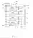
FIG. 1 is a magnetic interface circuit 100 of a first embodiment in accordance with the present invention.
The magnetic interface circuit 100 is used for a modular jack connecting between a network cable and a circuit board and is interfaced between a cable side 10 and a circuit side 20 of a networking communication channel. The magnetic interface circuit 100 includes four transmit channel 40. Each transmit channel 40 is identical and includes an isolation transformer 1 and a 3-wire CMC 2 with one of the windings of the isolation transformer 1 connected to the cable side 10 and the 3-wire CMC 2 connected between the other winding of the isolation transformer 1 and the circuit side 20 of the channel. The transformer 1 has a first winding 11 connected to the cable side 10 and a second winding 12 connected to the circuit side 20. The first winding 11 has two outputs 111 connected to the cable side 10 and a first center tap 112 connected to a discharge device 3 for connecting to ground 4. The discharge device 3 is formed of two adjacent conductive pads disposed on a printed circuit board. The discharge device 3 also could be replaced by a capacitor or a capacitor connecting with four resistors (Bob-smith circuit). The second winding 12 has two outputs 121 and a second center tap 122 connected to the circuit side 20. The 3-wire CMC 2 has a middle or center winding 22 and two outer windings 21. The two outer windings 21 is connected between the two outputs 121 of the second winding 12 and the circuit side 20. The center winding 22 does not connect with the transformer 1 but has two opposite ends 221 both used for connecting to ground 5. The circuit side 20 has a power supply 201 and a grounding point 202. The power supply 201 is parallel connected with the grounding point 202. The second center tap 122 is series connected with the power supply 201 and the grounding pointing 202 respectively. There is a capacitor 6 series connected between the second center tap 122 and the grounding point 202.
FIG. 3 shows a transmit channel 40 of the FIG. 1 transmitting a high frequency noise. High frequency noise is transmitted through the two outer windings 21 and could be coupled to the center winding 22 and directly absorbed to ground 5.
Referring to FIG. 4, line A shows an existing magnetic interface circuit's test data and line B shows the present invention's test data. As shown in FIG. 4, the present invention has a better filtering performance (common mode noise reduction) comparing to existing magnetic interface circuit in high frequency noise (or high speed transmit).
FIG. 2 is a magnetic interface circuit 100′ of a second embodiment in accordance with the present invention, which also has a better filtering performance compared to existing magnetic interface circuit in high frequency noise.
The magnetic interface circuit 100′ is used for a modular jack connecting between a network cable and a circuit board and is interfaced between a cable side 10′ and a circuit side 20′ of a networking communication channel. The magnetic interface circuit 100′ includes four transmit channel 40′. Each transmit channel 40′ is identical and includes an isolation transformer 1′ and a 3-wire CMC 2′ with one of the windings of the isolation transformer 1′ connected to the circuit side 20′ and the 3-wire CMC 2′ connected between the other winding of the isolation transformer 1′ and the cable side 20′ of the channel. The transformer 1′ has a first winding 11′ connected to the cable side 10′ and a second winding 12′ connected to the circuit side 20′. The first winding 11′ has two outputs 111′ connected to the cable side 10′ and a first center tap 112′ connecting to a discharge device 3′ for connecting to ground 4′. The discharge device 3′ is formed of two adjacent conductive pads disposed on a printed circuit board. The discharge device 3′ also could be replaced by a capacitor or a capacitor connecting with four resistors (Bob-smith circuit). The second winding 12′ has two outputs 121′ and a second center tap 122′ connecting to the circuit side 20′. The 3-wire CMC 2′ has a center winding 22′ and two outer windings 21′. The two outer windings 21′ is connected between the two outputs 111′ of the first winding 11′ and the circuit side 20′. The center winding 22′ does not connect with the transformer 1′ but has two opposite ends 221′ both using for connecting to ground 5′. The circuit side 20′ has a power supply 201′ and a grounding point 202′. The power supply 201′ is parallel connected with the grounding point 202′. The second center tap 122′ is series connected with the power supply 201′ and the grounding pointing 202′ respectively. There is a capacitor 6′ series connected between the second center tap 122′ and the grounding point 202′.
It is to be understood, however, that even though numerous characteristics and advantages of the present invention have been set forth in the foregoing description, together with details of the structure and function of the invention, the disclosure is illustrative only, and changes may be made in detail, especially in matters of shape, size, and arrangement of parts within the principles of the invention to the full extent indicated by the broad general meaning of the members in which the appended claims are expressed.
Claims
What is claimed is:1. A magnetic interface circuit for interfacing between a cable side and a circuit side of a networking communication channel, comprising:
a transformer having a first winding connected to the cable side of the channel and a second winding connected to the circuit side of the channel, each of the first and second windings having two output ports; and
a 3-wire common mode choke having a center winding and two outer windings, the outer windings being respectively connected to the output ports of the first or second winding, the center winding having two opposite ends for connecting to ground.
2. The magnetic interface circuit as claimed in claim 1, wherein the two opposite ends of the center winding are directly connected to ground.
3. The magnetic interface circuit as claimed in claim 1, wherein the outer windings of the 3-wire common mode choke are respectively connected to the output ports of the first winding.
4. The magnetic interface circuit as claimed in claim 1, wherein the outer windings of the 3-wire common mode choke are respectively connected to the output ports of the second winding.
5. The magnetic interface circuit as claimed in claim 1, wherein the first winding has a first center tap connecting to a discharge device for connecting to ground.
6. The magnetic interface circuit as claimed in claim 5, wherein the discharge device is formed of two adjacent conductive pads disposed on a printed circuit board.
7. The magnetic interface circuit as claimed in claim 5, wherein the discharge device includes a capacitor.
8. The magnetic interface circuit as claimed in claim 1, wherein the second winding has a second center tap connecting to the circuit side of the channel.
9. The magnetic interface circuit as claimed in claim 8, further comprising a power supply and a grounding point parallel connected on the circuit side, and wherein the second center tap is series connected with the power supply and the grounding point, respectively.
10. The magnetic interface circuit as claimed in claim 9, further including a capacitor series connected between the second center tap and the grounding point.
11. A magnetic interface circuit for interfacing between a cable side and a circuit side of a networking communication channel, comprising:
a transformer having a first winding connected to the cable side of the channel, and a second winding interacting with the first winding and connected to the circuit side of the channel, each of the first and second windings having two output ports; and
a 3-wire common mode choke having a center winding and two outer windings interacting with one another, the two outer windings being respectively being part of the two output ports of one of the first and the second winding, the center winding having two opposite ends connecting to ground.
12. The magnetic interface circuit as claimed in claim 11, wherein the two opposite ends of the center winding are directly connected to ground.
13. The magnetic interface circuit as claimed in claim 11, wherein the outer windings of the 3-wire common mode choke are respectively connected to the output ports of the first winding.
14. The magnetic interface circuit as claimed in claim 11, wherein the outer windings of the 3-wire common mode choke are respectively connected to the output ports of the second winding.
15. The magnetic interface circuit as claimed in claim 11, wherein the first winding has a first center tap connecting to a discharge device for connecting to ground.
16. The magnetic interface circuit as claimed in claim 15, wherein the discharge device is formed of two adjacent conductive pads disposed on a printed circuit board.
17. The magnetic interface circuit as claimed in claim 15, wherein the discharge device includes a capacitor.
18. The magnetic interface circuit as claimed in claim 11, wherein the second winding has a second center tap connecting to the circuit side of the channel.
19. The magnetic interface circuit as claimed in claim 18, further comprising a power supply and a grounding point parallel connected on the circuit side, and wherein the second center tap is series connected with the power supply and the grounding point, respectively.
20. The magnetic interface circuit as claimed in claim 19, further including a capacitor series connected between the second center tap and the grounding point.
Images & Drawings included:


Sources:
- United States Patent and Trademark Office - verify current appl. status at the USPTO↗
Recent applications in this class:
- » 20250293656 2025-09-18
FILTER CIRCUIT - » 20250286528 2025-09-11
NOISE FILTER AND POWER CONVERSION APPARATUS - » 20250260379 2025-08-14
REDUCING THE EFFECT OF PARASITIC CAPACITANCE IN A HIGH-PASS FILTER EMPLOYED IN PARALLEL WITH ANOTHER FILTER IN A SWITCHING CONFIGURATION - » 20250253821 2025-08-07
EMI FILTERING CIRCUIT FOR EV/HEV BATTERY CHARGERS - » 20250247066 2025-07-31
ISOLATION COMMUNICATIONS CHANNEL USING DIRECT DEMODULATION AND DATA-EDGE ENCODING - » 20250233572 2025-07-17
MULTILAYER ELECTRONIC COMPONENT - » 20250233571 2025-07-17
RF FILTER TOPOLOGY FOR SUBSTRATE SUPPORT ASSEMBLY - » 20250219606 2025-07-03
SIGNAL TRANSMISSION CIRCUIT AND ELECTRONIC DEVICE - » 20250219605 2025-07-03
ANALOG STORAGE USING MEMORY DEVICE - » 20250192747 2025-06-12
INTEGRATED NOISE FILTER
Recent applications for this Assignee:
- » 20250218287 2025-07-03
METHOD OF GENERATING AND PROMPTING TRAFFIC INFORMATION, AND ROADSIDE DEVICE THEREOF - » 20250178535 2025-06-05
METHOD FOR CONSTRUCTING 3D PANORAMIC VIEW MODEL, VEHICLE-MOUNTED DEVICE, AND STORAGE MEDIUM - » 20250074444 2025-03-06
METHOD FOR EARLY WARNING A BLIND AREA, ELECTRONIC DEVICE AND STORAGE MEDIUM - » 20240416754 2024-12-19
DISPLAY CONTROL DEVICE, DISPLAY EQUIPMENT, AND VEHICLE EMPLOYING DEVICE - » 20240411051 2024-12-12
Light-emitting device array and optical transceiver system having the same - » 20240324114 2024-09-26
DISPLAY CONTROL DEVICE AND VEHICLE EMPLOYING DEVICE - » 20240295957 2024-09-05
METHOD FOR CONTROLLING ELECTRONIC DEVICE, ELECTRONIC DEVICE AND COMPUTER STROAGE MEDIUM EMPLOYING METHOD - » 20240257357 2024-08-01
METHOD FOR DETECTING OBSTACLES, ELECTRONIC DEVICE, AND STORAGE MEDIUM - » 20240203133 2024-06-20
LANE LINE RECOGNITION METHOD, ELECTRONIC DEVICE AND STORAGE MEDIUM - » 20240194999 2024-06-13
Robot using limiting device for locking battery