Light guide plate and backlight module having the light guide plate
US20140313768A1
2014-10-23
14/256,073
2014-04-18
✅ Patent granted
US 9,110,206 B2
2015-08-18
-
-
Jason Moon Han
Novak Druce Connolly Bove + Quigg LLP
2034-04-18
Abstract:
A light guide plate includes a light incident surface for incident light, a light emitting surface for emitting the light, and microstructures formed on the light emitting surface to collimate the light.
Assignee:
- HON HAI PRECISION INDUSTRY CO., LTD. 10,014 🇹🇼 New Taipei, Taiwan
Applicant:
Interested in similar patents?
Get notified when new applications in this technology area are published.
Classification:
G02B6/0036 » CPC main
Light guides specially adapted for lighting devices or systems the light guides being planar or of plate-like form; Means for improving the coupling-out of light from the light guide provided on the surface of the light guide or in the bulk of it 2-D arrangement of prisms, protrusions, indentations or roughened surfaces
G02B6/0031 » CPC further
Light guides specially adapted for lighting devices or systems the light guides being planar or of plate-like form; Means for improving the coupling-in of light from the light source into the light guide provided by one optical element, or plurality thereof, placed between the light guide and the light source, or around the light source Reflecting element, sheet or layer
G02B6/0053 » CPC further
Light guides specially adapted for lighting devices or systems the light guides being planar or of plate-like form; Means for improving the coupling-out of light from the light guide provided by one optical element, or plurality thereof, placed on the light output side of the light guide Prismatic sheet or layer; Brightness enhancement element, sheet or layer
G09F13/08 IPC
Illuminated signs; Luminous advertising; Signs, boards or panels, illuminated from behind the insignia using both translucent and non-translucent layers
G09F13/04 IPC
Illuminated signs; Luminous advertising Signs, boards or panels, illuminated from behind the insignia
Description
FIELD
The present disclosure relates to backlight modules and, particularly, to a light guide plate and a backlight module having the light guide plate.
BACKGROUND
To increase an illumination brightness of the backlight modules, high power light sources are required, which increase manufacturing and use costs of the backlight modules.
Therefore, it is desirable to provide a light guide plate and a backlight module having a light guide plate that can overcome the above-mentioned problems.
BRIEF DESCRIPTION OF THE DRAWINGS
Many aspects of the present disclosure can be better understood with reference to the following drawings. The components in the drawings are not necessarily drawn to scale, the emphasis instead being placed upon clearly illustrating the principles of the present disclosure.
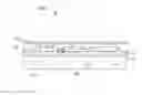
FIG. 1 is a cross-sectional schematic view of a backlight module, according to an embodiment.
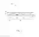
FIG. 2 is an isometric schematic view of a light guide plate of the backlight module of FIG. 1.
DETAILED DESCRIPTION
The disclosure is illustrated by way of example and not by way of limitation in the figures of the accompanying drawings in which like references indicate similar elements. It should be noted that references to “an” or “one” embodiment in this disclosure are not necessarily to the same embodiment, and such references mean “at least one.” The references “a plurality of” and “a number of” mean “at least two.”
Embodiments of the present disclosure will be described with reference to the drawings.
FIGS. 1-2 show a backlight module 100 that includes a light guide plate 10, a number of light sources 20, a reflective sheet 30, and a brightness enhancement film 40.
The light guide plate 10 can be made of polycarbonate, polymethyl methacrylate (PMMA), methyl methacrylate, styrene copolymer (MS), polyethylene terephthalate (PETG), polystyrene (PS) or any compound thereof.
The light guide plate 10 is substantially rectangular and includes a light incident surface 11 and a light emitting surface 12 opposite to the light incident surface 11. The light guide plate 10 also includes microstructures 13 formed on the light emitting surface 12.
In this embodiment, the microstructures 13 include a number of triangular prisms 131 bulged up from the light emitting surface 12. The triangular prisms 131 are arranged in parallel with each other and extend through the light emitting surface 12 along a direction that is substantially parallel with a widthwise direction or a lengthwise direction of the light emitting surface 12. Each triangular prism 131 includes a first surface 1311 and a second surface 1312, each of which connects each other and the light emitting surface 12. In this embodiment, a cross-section of the triangular prism 131 is substantially an isosceles triangle.
An included angle θ between the first surface 1311 and the second surface 1312 falls in a range from about 130 degrees to about 170 degrees or from about 130 degrees to about 150 degrees, or is about 130 degrees. An intersecting line 1313 of the first surface 1311 and the second surface 1312 is substantially parallel with the light emitting surface 12. A distance H between the intersecting line 1313 and the light emitting surface 12 falls in a range from about 1.3 microns to 5.5 microns or from about 4 microns to about 5.5 microns, or is about 5.5 microns. A pitch P between each two adjacent intersecting lines 1313 falls in a range from about 30 microns to about 50 microns or from about 40 to about 50 microns, or is about 50 microns.
The light sources 20 are positioned at a side of the light incident surface 11 and are configured for emitting light to the light incident surface 11. As such, the light can be collimated by the microstructures 131 to increase illumination brightness of the backlight module 100 in the normal direction. In detail, experimental results show that, within the ranges specified above, the collimation of the light increases with the decreasing of the included angle θ and the increasing of the distance H and the pitch P. That is, the collimation of the light can reach the maximum when the included angle θ is about 130 degrees, the distance H is about 5.5 microns, and the pitch P is about 50 microns.
The reflective sheet 30 is positioned at a side of the light sources 20 opposite to the light guide plate 10 and is configured for reflecting the light to the light incident surface 11 to increase illumination brightness of the backlight module 100.
The brightness enhancement film 40 is positioned at a side of the light emitting surface 12 to further increase the illumination brightness of the backlight module 100.
It will be understood that the above particular embodiments are shown and described by way of illustration only. The principles and the features of the present disclosure may be employed in various and numerous embodiments thereof without departing from the scope of the disclosure. The above-described embodiments illustrate the possible scope of the disclosure but do not restrict the scope of the disclosure.
Claims
What is claimed is:1. A light guide plate, comprising:
a light incident surface for receiving incident light;
a light emitting surface for emitting the light; and
microstructures formed on the light emitting surface to collimate the light.
2. The light guide plate of claim 1, wherein the microstructures comprise a plurality of triangular prisms bulged up from the light emitting surface, the triangular prisms are arranged in parallel with each other and extend through the light emitting surface along a direction that is substantially parallel with a widthwise direction or a lengthwise direction of the light emitting surface, each triangular prism comprises a first surface and a second surface, each of which connects each other and the light emitting surface, an included angle between the first surface and the second surface falls in a range from about 130 degrees to about 170 degrees, an intersecting line of the first surface and the second surface is substantially parallel with the light emitting surface, a distance between the intersecting line and the light emitting surface falls in a range from about 1.3 microns to 5.5 microns, and a pitch between each two adjacent intersecting lines falls in a range from about 30 microns to about 50 microns.
3. The light guide plate of claim 2, wherein the included angle falls into a range from about 130 degrees to about 150 degrees.
4. The light guide plate of claim 2, wherein the included angle is about 130 degrees.
5. The light guide plate of claim 2, wherein the distance falls in a range from about 4 microns to about 5.5 microns.
6. The light guide plate of claim 2, wherein the distance is about 5.5 microns.
7. The light guide plate of claim 2, wherein the pitch falls into a range from about 40 microns to 50 microns.
8. The light guide plate of claim 2, wherein the pitch is about 50 microns.
9. The light guide plate of claim 2, wherein a cross-section of the triangular prism is substantially an isosceles triangle.
10. A backlight module, comprising:
a plurality of light sources for emitting light;
a light guide plate, including a light incident surface facing the light sources for receiving the light, a light emitting surface for emitting the light, and microstructures formed on the light emitting surface to collimate the light; and
a reflective sheet positioned at a side of the light sources opposite to the light guide plate and configured to reflect light from the light sources into the incident surface.
11. The backlight module of claim 10, wherein the microstructures comprise a plurality of triangular prisms bulged up from the light emitting surface, the triangular prisms are arranged in parallel with each other and extend through the light emitting surface along a direction that is substantially parallel with a widthwise direction or a lengthwise direction of the light emitting surface, each triangular prism comprises a first surface and a second surface, each of which connects each other and the light emitting surface, an included angle between the first surface and the second surface falls in a range from about 130 degrees to about 170 degrees, an intersecting line of the first surface and the second surface is substantially parallel with the light emitting surface, a distance between the intersecting line and the light emitting surface falls in a range from about 1.3 microns to 5.5 microns, a pitch between each two adjacent intersecting lines falls in a range from about 30 microns to about 50 microns.
12. The backlight module of claim 11, wherein the included angle falls into a range from about 130 degrees to about 150 degrees.
13. The backlight module of claim 11, wherein the included angle is about 130 degrees.
14. The backlight module of claim 11, wherein the distance falls in a range from about 4 microns to about 5.5 microns.
15. The backlight module of claim 11, wherein the distance is about 5.5 microns.
16. The backlight module of claim 11, wherein the pitch falls into a range from about 40 microns to 50 microns.
17. The backlight module of claim 11, wherein the pitch is about 50 microns.
18. The backlight module of claim 11, wherein a cross-section of the triangular prism is substantially an isosceles triangle.
Images & Drawings included:

Sources:
- United States Patent and Trademark Office - verify current appl. status at the USPTO↗
Similar patent applications:
- » 20150277016
Light guide plate, backlight module, and method for manufacturing light guide plate - » 20140160795
Light guide plate, backlight module and display device both with the light guide plate - » 20160320544
Light guide plate and backlight module using the light guide plate - » 20140119056
Light Guide Plate and Backlight Module Using the Light Guide Plate - » 20100002467
Light Guide Plate and Backlight Module Using the Light Guide Plate - » 20190383991
Light guide plate and backlight module comprising the light guide plate - » 20160245978
Light guide plate, backlight module of liquid crystal display panel, and device for manufacturing light guide plate - » 20110149595
Light guide plate, backlight module and method of guiding light - » 20110199785
Backlight module, light guide plate thereof and ink thereof - » 14420900
Light guide plate, backlight module, and liquid crystal display device
Recent applications in this class:
- » 20250291103 2025-09-18
LIGHT SOURCE MODULE - » 20250277928 2025-09-04
BACKLIGHT MODULE AND DISPLAY DEVICE - » 20250264653 2025-08-21
PRISMS FOR INDEPENDENT CONTROL OVER VIRTUAL IMAGE AND WORLD LEAKAGE ANGLES - » 20250251541 2025-08-07
SHAPED PART AND METHOD FOR PRODUCING A SHAPED PART - » 20250216593 2025-07-03
A LIGHT COUPLING DEVICE FOR COUPLING LIGHT INTO A DISPLAY PANEL - » 20250199229 2025-06-19
ELECTRONIC DEVICE AND SOFT LIGHT-GUIDE MEMBER THEREOF - » 20250180796 2025-06-05
WAVEGUIDE FOR DISPLAYING AN IMAGE, AND HOLOGRAPHIC DISPLAY HAVING SUCH A WAVEGUIDE - » 20250164683 2025-05-22
Electronic device - » 20250147219 2025-05-08
FRONT LIGHT MODULE - » 20250147218 2025-05-08
TRIM PART HAVING A TWO-DIMENSIONAL LIGHT GUIDE
Recent applications for this Assignee:
- » 20250218287 2025-07-03
METHOD OF GENERATING AND PROMPTING TRAFFIC INFORMATION, AND ROADSIDE DEVICE THEREOF - » 20250178535 2025-06-05
METHOD FOR CONSTRUCTING 3D PANORAMIC VIEW MODEL, VEHICLE-MOUNTED DEVICE, AND STORAGE MEDIUM - » 20250074444 2025-03-06
METHOD FOR EARLY WARNING A BLIND AREA, ELECTRONIC DEVICE AND STORAGE MEDIUM - » 20240416754 2024-12-19
DISPLAY CONTROL DEVICE, DISPLAY EQUIPMENT, AND VEHICLE EMPLOYING DEVICE - » 20240411051 2024-12-12
Light-emitting device array and optical transceiver system having the same - » 20240324114 2024-09-26
DISPLAY CONTROL DEVICE AND VEHICLE EMPLOYING DEVICE - » 20240295957 2024-09-05
METHOD FOR CONTROLLING ELECTRONIC DEVICE, ELECTRONIC DEVICE AND COMPUTER STROAGE MEDIUM EMPLOYING METHOD - » 20240257357 2024-08-01
METHOD FOR DETECTING OBSTACLES, ELECTRONIC DEVICE, AND STORAGE MEDIUM - » 20240203133 2024-06-20
LANE LINE RECOGNITION METHOD, ELECTRONIC DEVICE AND STORAGE MEDIUM - » 20240194999 2024-06-13
Robot using limiting device for locking battery