Light signal gathering device and optical module used thereof
US20140314380A1
2014-10-23
14/260,209
2014-04-23
✅ Patent granted
US 9,383,531 B2
2016-07-05
-
-
Ryan Lepisto | Guy Anderson
Wei Te Chung | Ming Chieh Chang
2034-04-23
Abstract:
An optical module (100) set on a substrate for assembling with a fiber (72) and comprises a light signal gathering device (8), a plurality of electrical contacts (2) set on the light signal gathering device (8) and an optoelectronic device (4) soldered to the electrical contacts (2) for receiving the light signals refocused by the light signal gathering device (8) and transferring the light signals to electrical signals, the light signal gathering device (8) includes a resin body (1) and a light signal gathering portion set on the resin body (1) for refocusing light signals.
Assignee:
- HON HAI PRECISION INDUSTRY CO., LTD. 10,014 🇹🇼 New Taipei, Taiwan
Applicant:
Interested in similar patents?
Get notified when new applications in this technology area are published.
Classification:
G02B6/4295 » CPC main
Light guides; Coupling light guides; Coupling light guides with opto-electronic elements coupling with semiconductor devices activated by light through the light guide, e.g. thyristors, phototransistors
G02B6/4274 » CPC further
Light guides; Coupling light guides; Coupling light guides with opto-electronic elements; Packages, e.g. shape, construction, internal or external details Electrical aspects
G02B6/425 » CPC main
Light guides; Coupling light guides; Coupling light guides with opto-electronic elements; Packages, e.g. shape, construction, internal or external details comprising arrays of active devices and fibres Optical features
G02B6/4201 » CPC further
Light guides; Coupling light guides; Coupling light guides with opto-electronic elements Packages, e.g. shape, construction, internal or external details
G02B6/4249 » CPC further
Light guides; Coupling light guides; Coupling light guides with opto-electronic elements; Packages, e.g. shape, construction, internal or external details comprising arrays of active devices and fibres
G02B6/4292 » CPC further
Light guides; Coupling light guides; Coupling light guides with opto-electronic elements the light guide being disconnectable from the opto-electronic element, e.g. mutually self aligning arrangements
G02B6/4293 » CPC further
Light guides; Coupling light guides; Coupling light guides with opto-electronic elements the light guide being disconnectable from the opto-electronic element, e.g. mutually self aligning arrangements hybrid electrical and optical connections for transmitting electrical and optical signals
G02B6/36 IPC
Light guides; Coupling light guides Mechanical coupling means
G02B6/42 IPC
Light guides; Coupling light guides Coupling light guides with opto-electronic elements
G02B6/32 » CPC further
Light guides; Coupling light guides; Optical coupling means having lens focusing means positioned between opposed fibre ends
G02B6/4214 » CPC further
Light guides; Coupling light guides; Coupling light guides with opto-electronic elements; Packages, e.g. shape, construction, internal or external details the coupling comprising intermediate optical elements, e.g. lenses, holograms the intermediate optical element having redirecting reflective means, e.g. mirrors, prisms for deflecting the radiation from horizontal to down- or upward direction toward a device
Description
BACKGROUND OF THE INVENTION
1. Field of the invention
The present invention relates to a light signal gathering device, and more particularly to a light signal device for gathering light signals and transferring the light signals to a optoelectronic device to transfer the light signals to electrical signals.
2. Description of related art
Chinese patent No. 102667565A issued to Enplas on Sep. 12, 2012 discloses a conventional optical module for transferring light signals to electrical signals. The light signals emitted by the fibers are transferred in a horizontal direction. But, the optical module can only receive the light signal transferred in a vertical direction. So, the transferring direction of the light signals is changed by a resin body and use lenses to gather the light signals. Thus, the light signals can be received by the optical module to be transferred to electrical signals. The lens adds the cost. At the same time, the position of the lens must in align with the optical module make it hard to be assembled.
Hence, it is desirable to provide an improved optical module to overcome the aforementioned disadvantages.
SUMMARY OF THE INVENTION
Accordingly, an object of the present invention is to provide a light signal gathering device assembled with the optoelectronic device to make the light signals can be received by the optoelectronic device precisely.
According to one aspect of the present invention, an optical module set on a substrate for assembling with a fiber and comprises a light signal gathering device, a plurality of electrical contacts set on the light signal gathering device and an optoelectronic device soldered to the electrical contacts for receiving the light signals refocused by the light signal gathering device and transferring the light signals to electrical signals, the light signal gathering device includes a resin body and a light signal gathering portion set on the resin body for refocusing light signals.
Other objects, advantages and novel features of the invention will become more apparent from the following detailed description when taken in conjunction with the accompanying drawings, in which:
BRIEF DESCRIPTION OF THE DRAWINGS
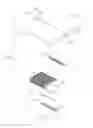
FIG. 1 is an exploded view of the optical module according to a first embodiment of the present invention;
FIG. 2 is an isometric view of the light signal gathering device according to the present invention;
FIG. 3 is an enlarge view of the circular portion of the light signal gathering device as shown in FIG. 2;
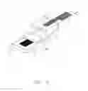
FIG. 4 is an exploded view of the optical module, the substrate and the fiber assembly;
FIG. 5 is an assembled view of the optical module, the substrate and the fiber assembly;
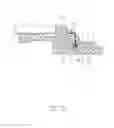
FIG. 6 is a cross-sectional view of the optical module, the substrate and the fiber assembly as shown in FIG. 5 along line 6-6;
FIG. 7 is an enlarge view of the circular portion as shown in FIG. 6;
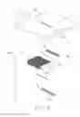
FIG. 8 is exploded view of a second embodiment of the optical module according to the present invention; and
FIG. 9 is a cross-sectional view of one portion of the optical module as showing in FIG. 8.
DETAILED DESCRIPTION OF THE INVENTION
Reference will now be made to the drawings to describe the present invention in detail.
FIGS. 1 to 5 illustrate an optical module 100 in accordance to a first embodiment of the present invention. The optical module 100 is set on a substrate 6 for transfers the light signals sent by fiber assembly 7 to electrical signals. The optical module 100 includes a light signal gathering device 8, a plurality of electrical contacts 2 and a retention contact 3 set on the light signal gathering device 8 and an optoelectronic device 4, soldered to the electrical contacts 2 and the retention contacts 3 by soldering materials 5.
Referring to FIG. 1 to FIG. 3, the light signal gathering device 8 includes a resin body 1 and a plurality of passageways 101 set on the resin body 1. The resin body 1 includes a bottom surface 11 assembled to the substrate 6 and a top surface 10 opposite to the bottom surface 11. The resin body 1 includes a plurality of slots 112 and a recess 113 recessed from the bottom surface 11 to the inner of the resin body 1. The slots 112 extend in a direction perpendicular to that of the recess 113. The resin body 1 further includes a plurality of supporting portions 110 extending from the bottom surface 11 and a pair of through holes 102 penetrating the top surface 10 and the bottom surface 11. The passageways 101 further penetrate the top surface 10 and the bottom surface 11.
Referring to FIG. 7, the passageways 101 are configured to funnel shape and each includes a top end 1010 for the light signals entering and a bottom end 1011 opposite to the top end 1010 for the light signals coming out. The area of the top end 1010 is larger than that of the bottom end 1011, thus the light signals enter from the top end 1010 be gathered and come out from the bottom end 1011. The passageways 101 are filled with optical cement 1012 of the inner surface of the passageways 101 are plated with metal layer. The refractive index of the optical cement 1012 is larger than that of the resin body 1. The best situation is the refractive index of the optical cement 1012 larger than 1.6 and the refractive index of the resin body 1 smaller than 1.5 to achieve less loss of the light signals.
The electrical contact 2 includes a base portion 21, a first tail portion 22 and a second tail portion 23 extending from two opposite ends of the base portion 21. The retention contact 3 includes a position portion 31 and a plurality of position ends 32 extending from the position portion 31. The optoelectronic device 4 includes a plurality of first pads 41 locating in a first row and a plurality of second pads 42 locating in a second row.
Referring to FIG. 4 and FIG. 7, when assemble the optical module 100, the electrical contacts 2 are assembled to the slots 112 and the retention contacts 3 are assembled to the recesses 113 of the resin body 1, respectively; the first pads 41 of the optoelectronic device 4 are soldered to the position ends 32 of the retention contact 3 through soldering materials 5, and the second pads 42 of the optoelectronic device 4 are soldered to the first tail portions 22 of the electrical contacts 3 through soldering materials 5, thus the optoelectronic device 4 is in align with the passageways 101 to receive the light signals. The retention contacts 3 are used to position the optoelectronic device 4.
When the optical module 100 is used, the second tail portions 23 of the electrical contacts 2 are soldered to the substrate 6 through soldering materials 5, the second tail portions 23 extending beyond the bottom surface 11, the optoelectronic device 4 and the supporting portions 110 supports on the substrate 6 and the position holes 61 of the substrate 6 are in align with the through holes 102 of the optical module 100. The fiber assembly 7 includes a pair of posts 73. The pair of posts 73 is assembled to the through holes 102 of the optical module 100 and the position holes 61 of the substrate 6 to position the fiber assembly 7, the optical module 100 and the substrate 6.
Referring to FIG. 6, the lens 72 of the fiber assembly 7 changes the diverging light signals sent by the fibers 71 to paralleled light signals and then be refocused by the light signal gathering device 8, due to the optoelectronic device 4 being in align with the light signal gathering device 8 accurately, the light signals can be received by the optoelectronic device 4 accurately.
FIGS. 8-9 shows a second embodiment of the optical module 100′. The difference between the two embodiments is the light signal gathering device 8′ in the second embodiment includes a plurality of lenses 101′ set on the top surface 10′ of the resin body 1′ and in align with the optoelectronic device 4. The lenses 101′ are used to gather light signals and then the light signals can be received by the optoelectronic device 4 accurately.
The light signal gathering device 8, 8′ in this invention includes a resin body 1, 1′ and a light signal gathering portion set on the resin body 1, 1′. The light signal gathering portion is a passageway 101 with funnel shape and penetrates the resin body 1 or a lens 101′ set on the top surface 10′ of the resin body 1′.
While the preferred embodiments in accordance with the present invention has been shown and described, equivalent modifications and changes known to persons skilled in the art according to the spirit of the present invention are considered within the scope of the present invention as defined in the appended claims.
Claims
What is claimed is:1. An optical module set on a substrate for assembling with a fiber, comprising:
a light signal gathering device including a resin body and a light signal gathering portion set on the resin body for refocusing light signals;
a plurality of electrical contacts set on the light signal gathering device; and
an optoelectronic device soldered to the electrical contacts for receiving the light signals refocused by the light signal gathering portion and transferring the light signals to electrical signals.
2. The optical module as claimed in claim 1, wherein the light signal gathering portion is a passageway penetrating the resin body, the passageway is configured to funnel shape and includes a top end for the light signals entering and a bottom end opposite to the top end and smaller than the top end for the light signals coming out.
3. The optical module as claimed in claim 2, wherein the passageway is filled with optical cement, the refractive index of the optical cement is larger than that of the resin body.
4. The optical module as claimed in claim 3, wherein the refractive index of the optical cement is larger than 1.6 and the refractive index of the resin body is smaller than 1.5.
5. The optical module as claimed in claim 2, wherein the inner surface of the passageway is plated with metal layer.
6. The optical module as claimed in claim 1, wherein the light signal gathering portion is a lens set on the resin body.
7. The optical module as claimed in claim 1, wherein the electrical contact includes a base portion positioned in the resin body, a first tail portion and a second tail portion extending from two opposite ends of the base portion, the first tail portion is soldered to the optoelectronic device and the second tail is soldered to the substrate.
8. The optical module as claimed in claim 7, wherein the optical module further includes a retention contact assembled to the resin body and soldered to the optoelectronic device.
9. The optical module as claimed in claim 8, wherein the retention contact includes a position portion positioned in the resin body and a plurality of position ends extending from the position portion for being soldered to the optoelectronic device.
10. The optical module as claimed in claim 9, wherein the resin body includes a bottom surface assembled to the substrate, a plurality of slots and a recess recessed from the bottom surface to the inner of the resin body, the slots extend in a direction perpendicular to that of the recess, the electrical contacts are received in the slots and the retention contact is received in the recess.
11. The optical module as claimed in claim 10, wherein the second tail portion extends beyond the resin body.
12. A light signal gathering device for refocusing light signals, comprising:
a resin body with a plurality of passageways penetrating the resin body, each of the passageways is configured to funnel shape and including a top end for the light signals entering and a bottom end opposite to the top end and smaller than the top end for the light signals coming out.
13. The light signal gathering device as claimed in claim 12, wherein the passageway is filled with optical cement, the refractive index of the optical cement is larger than that of the resin body.
14. The light signal gathering device as claimed in claim 13, wherein the refractive index of the optical cement is larger than 1.6 and the refractive index of the resin body is smaller than 1.5.
15. The light signal gathering device as claimed in claim 13, wherein the inner surface of the passageway is plated with metal layer.
16. A light signal gathering device comprising:
a light guide body defining a tunnel structure with opposite top and bottom faces thereof wherein an opening of said tunnel structure in the top face is larger than that in the bottom face;
a circumference of said light guide body being configured not to allow light to escape therefrom except at the opening in the bottom face; and
an optoelectronic device intimately confronting the opening in the bottom face.
17. The light signal gathering device as claimed in claim 16, wherein the opening in the top face collects light from optical fiber assemblies.
18. The light signal gathering device as claimed in claim 16, wherein the light guide body is surrounded by a resin body, and a refractive index of the light guide body is smaller than that of the resin body.
19. The light signal gathering device as claimed in claim 18, wherein a plurality of conductive contacts are disposed in the resin body and soldered to the optoelectronic device.
20. The light signal gathering device as claimed in claim 16, wherein a metallic reflection layer is coated upon a circumferential surface of the light guide body.
Images & Drawings included:


Sources:
- United States Patent and Trademark Office - verify current appl. status at the USPTO↗
Recent applications in this class:
- » 20250224578 2025-07-10
PHOTODETECTORS WITH AN INTEGRATED WAVEGUIDE CORE - » 20250216635 2025-07-03
Optical Chip-to-Chip Interconnect and Method of Integration - » 20250102751 2025-03-27
MANAGING CO-PACKAGING OF PHOTONIC INTEGRATED CIRCUITS - » 20240427096 2024-12-26
FIBER OPTIC CABLE COUPLING ASSEMBLY - » 20240361549 2024-10-31
PHOTONIC STRUCTURE AND SEMICONDUCTOR STRUCTURE AND METHOD FOR MANUFACTURING THE SAME - » 20240272393 2024-08-15
Multicomponent photonically intra-die bridged assembly - » 20240272392 2024-08-15
Multicomponent photonically bridged assembly - » 20240219664 2024-07-04
Optical bridging element for separately stacked electrical ICs - » 20240142732 2024-05-02
Photonic Semiconductor Device and Method - » 20240027711 2024-01-25
OPTICAL MULTI-DIE INTERCONNECT BRIDGE WITH ELECTRICAL AND OPTICAL INTERFACES
Recent applications for this Assignee:
- » 20250218287 2025-07-03
METHOD OF GENERATING AND PROMPTING TRAFFIC INFORMATION, AND ROADSIDE DEVICE THEREOF - » 20250178535 2025-06-05
METHOD FOR CONSTRUCTING 3D PANORAMIC VIEW MODEL, VEHICLE-MOUNTED DEVICE, AND STORAGE MEDIUM - » 20250074444 2025-03-06
METHOD FOR EARLY WARNING A BLIND AREA, ELECTRONIC DEVICE AND STORAGE MEDIUM - » 20240416754 2024-12-19
DISPLAY CONTROL DEVICE, DISPLAY EQUIPMENT, AND VEHICLE EMPLOYING DEVICE - » 20240411051 2024-12-12
Light-emitting device array and optical transceiver system having the same - » 20240324114 2024-09-26
DISPLAY CONTROL DEVICE AND VEHICLE EMPLOYING DEVICE - » 20240295957 2024-09-05
METHOD FOR CONTROLLING ELECTRONIC DEVICE, ELECTRONIC DEVICE AND COMPUTER STROAGE MEDIUM EMPLOYING METHOD - » 20240257357 2024-08-01
METHOD FOR DETECTING OBSTACLES, ELECTRONIC DEVICE, AND STORAGE MEDIUM - » 20240203133 2024-06-20
LANE LINE RECOGNITION METHOD, ELECTRONIC DEVICE AND STORAGE MEDIUM - » 20240194999 2024-06-13
Robot using limiting device for locking battery