ENERGY MANAGEMENT SYSTEM
US20140337656A1
2014-11-13
14/275,979
2014-05-13
Abstract:
An energy management system is connected to a power supply unit and a power switch. The energy management system includes a power supply monitor, a power supply connector, and a baseboard management controller (BMC). The power supply monitor is connected to the BMC through an intelligent platform management interface (IPMI). The power supply monitor is utilized to read, count and record power signals from the BMC, and send commands according the power signals to control the power switch.
Assignee:
- HON HAI PRECISION INDUSTRY CO., LTD. 9,798 🇹🇼 New Taipei, Taiwan
Interested in similar patents?
Get notified when new applications in this technology area are published.
Classification:
G06F11/3062 » CPC main
Error detection; Error correction; Monitoring; Monitoring; Monitoring arrangements for monitoring environmental properties or parameters of the computing system or of the computing system component, e.g. monitoring of power, currents, temperature, humidity, position, vibrations where the monitored property is the power consumption
G06F11/30 IPC
Error detection; Error correction; Monitoring Monitoring
Description
FIELD
The present disclosure relates to an energy management system.
BACKGROUND
Power supply units usually lack the ability to measure and transmit energy consumption information.
BRIEF DESCRIPTION OF THE DRAWING
Many aspects of the embodiments can be better understood with reference to the following drawings. The components in the drawings are not necessarily drawn to scale, the emphasis instead being placed upon clearly illustrating the principles of the presented embodiments. Moreover, in the drawings, like reference numerals designate corresponding parts throughout the several views.
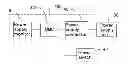
FIG. 1 is a block diagram of an embodiment of energy management system, comprising a power supply monitor, a baseboard management controller (BMC), and a power supply connector.
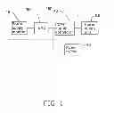
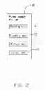
FIG. 2 is a block diagram of an embodiment of the power supply monitor of FIG. 1.
DETAILED DESCRIPTION
The disclosure is illustrated by way of example and not by way of limitation in the figures of the accompanying drawings in which like references indicate similar elements. It should be noted that references to “an” or “one” embodiment in this disclosure are not necessarily to the same embodiment, and such references mean “at least one.”
FIG. 1 illustrates an embodiment of an energy management system 100 of the present disclosure. In the embodiment, the energy management system 100 can comprise a power supply monitor 10, a baseboard management controller (BMC) 30, and a power supply connector 40. The energy management system 100 is connected to a power supply unit 80 of a server to manage the energy consumption information of the power supply unit 80. The energy management system 100 is connected to a power switch 90 to control the power switch 90.
The BMC 30 can be connected to the power supply unit 80 through the power supply connector 40 for detecting power signals from the power supply unit 80. The power supply monitor 10 can be connected to the BMC 30 through an intelligent platform management interface (IPMI). The power supply monitor 10 can receive the power signals from the BMC 30 through the IPMI, and then manages the power signals. The BMC 30 is connected to the power switch 90. The power supply monitor 10 controls the power switch 90 through the BMC 30.
FIG. 2 illustrates that the power supply monitor 10 can comprise a reading unit 11, a counting unit 12, a storage unit 13, and a control unit 14. The reading unit 11 is utilized to read the power signals from the BMC 30. The counting unit 12 is utilized to count the power signals to obtain energy consumption information of the power supply unit 80. The storage unit 13 is utilized to record the energy consumption information in a preset period of time. The control unit 14 is utilized to control the BMC 30 through the IPMI to control the power switch 90. For example, analyzing peak periods and off-peak periods for usage of the servers in a same domain according to the energy consumption information of the servers during a month, recorded in the storage unit 13, and then constituting a task that power on some of the servers during the peak periods, and turns off some servers in the off-peak periods for conserving energy.
In another embodiment, according to the price trend of electricity, part of the servers can be turned off during the peak periods, and be turned on in the off-peak periods, in order to save money.
Even though numerous characteristics and advantages of the disclosure have been set forth in the foregoing description, together with details of the structure and function of the disclosure, the disclosure is illustrative only, and changes can be made in the details given, including matters of shape, size, and arrangement of parts within the principles of the disclosure to the full extent indicated by the broad general meaning of the terms in which the appended claims are expressed.
Claims
What is claimed is:1. An energy management system connected to a power supply unit and a power switch, the energy management system comprising:
a power supply connector;
a baseboard management controller (BMC) connected to the power supply unit through the power supply connector for detecting power signals from the power supply unit, and connected to the power switch for controlling the power switch; and
a power supply monitor connected to the BMC, the power supply monitor comprising:
a reading unit to read the power signals from the BMC;
a counting unit to count the power signals to obtain energy consumption information of the power supply unit; and
a storage unit to record the energy consumption information in a preset period of time.
2. The energy management system of claim 1, wherein the power supply monitor further comprises a control unit to control the BMC to switch the power switch.
Images & Drawings included:
Sources:
- United States Patent and Trademark Office - verify current appl. status at the USPTO↗
Similar patent applications:
- » 20170072804
SMART ENERGY MANAGEMENT SYSTEMS FOR ELECTRIC AND HYBRID ELECTRIC VEHICLES WITH BIDIRECTIONAL CONNECTION, SMART ENERGY MANAGEMENT SYSTEM FOR AN ENERGY GENERATOR, METHOD FOR MANAGING ENERGY IN A SMART ENERGY MANAGEMENT SYSTEM AND METHOD FOR CONTROLLING THE OPERATION OF AN ENERGY GENERATOR - » 20230102528
VEHICLE ENERGY MANAGEMENT SYSTEM, VEHICLE COMPRISING SUCH VEHICLE ENERGY MANAGEMENT SYSTEM, AND METHOD OF CONTROLLING VEHICLE ENERGY MANAGEMENT SYSTEM - » 20140144785
ENERGY MANAGEMENT SYSTEM, INDUSTRIAL PLANT COMPRISING AN ENERGY MANAGEMENT SYSTEM AND METHOD FOR OPERATING AN ENERGY MANAGEMENT SYSTEM - » 20140242490
Energy management system, energy management apparatus, and power management method - » 20140142772
Energy management system, energy management method, program, server apparatus, and local server - » 20140214219
ENERGY MANAGEMENT SYSTEM, ENERGY MANAGEMENT METHOD, MEDIUM, AND SERVER - » 20140012427
ENERGY MANAGEMENT SYSTEM, ENERGY MANAGEMENT METHOD, PROGRAM SERVER APPARATUS, AND CLIENT APPARATUS - » 20110238232
Energy management system, energy management apparatus, and energy management method - » 20140244064
Energy management system, energy management apparatus, and power management method - » 20140257583
ENERGY MANAGEMENT SYSTEM, ENERGY MANAGEMENT METHOD, COMPUTER-READABLE MEDIUM, AND SERVER
Recent applications in this class:
- » 20250103455 2025-03-27
MULTI-LEVEL POWER MANAGEMENT OPERATION FRAMEWORK - » 20250068534 2025-02-27
ENVIRONMENTAL IMPACT POWER CONSUMPTION RATING FOR APPLICATIONS - » 20240427682 2024-12-26
CONVERTING TELEMETRY VALUES INTO COMMON DATA FORMATS IN A PROCESSOR-BASED SYSTEM IN AN INTEGRATED CIRCUIT (IC) CHIP - » 20240411654 2024-12-12
APPROXIMATING ENERGY USE OF SOFTWARE EXECUTING ON VIRTUAL MACHINES - » 20240320115 2024-09-26
METHOD AND SYSTEM FOR SYSTEM ON CHIP POWER CONSUMPTION ANALYSIS - » 20240311264 2024-09-19
DECOUPLING POWER AND ENERGY MODELING FROM THE INFRASTRUCTURE - » 20240232037 2024-07-11
SYSTEMS AND METHODS FOR ESTIMATING INFORMATION HANDLING SYSTEM PERFORMANCE CAPACITY BASED ON TEMPERATURE AND ACOUSTIC PARAMETERS - » 20240220386 2024-07-04
Systems and methods for managing power consumption of a distributed system - » 20240220385 2024-07-04
POWER SOURCE CONSUMPTION MANAGEMENT APPARATUS FOR FOUR-WAY SERVER - » 20240193062 2024-06-13
Burst power limit control in heterogeneous computing platforms
Recent applications for this Assignee:
- » 20240411051 2024-12-12
Light-emitting device array and optical transceiver system having the same - » 20240295957 2024-09-05
METHOD FOR CONTROLLING ELECTRONIC DEVICE, ELECTRONIC DEVICE AND COMPUTER STROAGE MEDIUM EMPLOYING METHOD - » 20240257357 2024-08-01
METHOD FOR DETECTING OBSTACLES, ELECTRONIC DEVICE, AND STORAGE MEDIUM - » 20240194999 2024-06-13
Robot using limiting device for locking battery - » 20240177502 2024-05-30
METHOD OF DETERMINING DEGREE OF CONGESTION OF COMPARTMENT, ELECTRONIC DEVICE AND STORAGE MEDIUM - » 20240140338 2024-05-02
ELECTROSTATIC ELIMINATING DEVICE AND VEHICLE - » 20240047565 2024-02-08
FIELD EFFECT TRANSISTOR AND METHOD FOR MAKING THE SAME - » 20240044098 2024-02-08
Monitoring device and well cover assembly - » 20240033856 2024-02-01
Deposition mask, mask member for deposition mask, method of manufacturing deposition mask, and method of manufacturing organic EL display apparatus - » 20230419653 2023-12-28
METHOD FOR DETECTING DEFECT OF IMAGES AND ELECTRONIC DEVICE