Valve device
US20140339452A1
2014-11-20
14/365,832
2012-12-18
✅ Patent granted
US 9,829,111 B2
2017-11-28
WO; PCT/EP2012/075912; 20121218
WO; WO2013/092561; 20130627
Mary McManmon | Richard K Durden
Cozen O'Connor
2032-12-18
Abstract:
A valve device has a housing, and a flow channel running in the housing, in which a valve flap is fastened on a shaft arranged perpendicularly to the flow direction. The shaft is rotatably mounted in housing. The bearing formed as a loose bearing is surrounded by a spring retainer, the base of which lies on a bearing bush of the loose bearing and has a jacket surface with a radial wavy shape.
Assignee:
- CONTINENTAL AUTOMOTIVE GMBH 2,462 🇩🇪 Hannover, Germany
Applicant:
Interested in similar patents?
Get notified when new applications in this technology area are published.
Classification:
F16K1/224 » CPC main
Lift valves or globe valves , i.e. cut-off apparatus with closure members having at least a component of their opening and closing motion perpendicular to the closing faces with pivoted closure-members with pivoted discs or flaps with axis of rotation crossing the valve member, e.g. butterfly valves Details of bearings for the axis of rotation
F16K1/22 IPC
Lift valves or globe valves , i.e. cut-off apparatus with closure members having at least a component of their opening and closing motion perpendicular to the closing faces with pivoted closure-members with pivoted discs or flaps with axis of rotation crossing the valve member, e.g. butterfly valves
F16K41/106 » CPC further
Spindle sealings with diaphragm, e.g. shaped as bellows or tube for use with rotating spindles or valves
F16K1/2268 » CPC further
Lift valves or globe valves , i.e. cut-off apparatus with closure members having at least a component of their opening and closing motion perpendicular to the closing faces with pivoted closure-members with pivoted discs or flaps with axis of rotation crossing the valve member, e.g. butterfly valves; Shaping or arrangements of the sealing Sealing means for the axis of rotation
F16K1/226 IPC
Lift valves or globe valves , i.e. cut-off apparatus with closure members having at least a component of their opening and closing motion perpendicular to the closing faces with pivoted closure-members with pivoted discs or flaps with axis of rotation crossing the valve member, e.g. butterfly valves Shaping or arrangements of the sealing
F16K41/10 » CPC further
Spindle sealings with diaphragm, e.g. shaped as bellows or tube
Description
CROSS-REFERENCE TO RELATED APPLICATIONS
This is a U.S. national stage of application No. PCT/EP2012/075912, filed on 18 Dec. 2012, which claims priority to the German Application No. 10 2011 089 080.7, filed 19 Dec. 2011, the content of both incorporated herein by reference.
BACKGROUND OF THE INVENTION
1. Field of the Invention
The invention relates to a valve device having a housing and having a flow duct which runs in the housing and in which a valve flap is fastened to a shaft arranged perpendicular to the flow direction, wherein the shaft is mounted rotatably in the housing.
2. Related Art
Valve devices of this type are typically used as exhaust-gas flaps in motor vehicles and are thus known. In the case of the known exhaust-gas flaps, the shaft is mounted, on both sides of the flow duct, in each case one bearing bushing. The bearing bushings are arranged in corresponding bores of the housing and are in the form of a fixed bearing and a floating bearing. The bores in the housing additionally have seals in order to prevent the exhaust gas that flows in the flow duct from passing out into the environment through the bores.
SUMMARY OF THE INVENTION
The invention is based on an object of providing a valve device which permits secure and reliable mounting of the shaft with the fewest possible components while ensuring reliable operation of the valve device.
The object is achieved in that the bearing, which is in the form of a floating bearing, is surrounded by a spring pot, the base of which spring pot bears against a bearing bushing of the floating bearing and the shell surface of which spring pot has a radially undulating shape.
The arrangement of a spring pot serves firstly to realize the sealing of the bearing point. At the same time, the spring pot serves to generate the preload of the floating bearing, such that the shaft can be mounted axially without play. No additional components are required for the two functions.
In one advantageous refinement, the spring pot surrounds the housing part that surrounds the bore.
Good cooling of the spring pot, with simultaneously good spring characteristics, are achieved if the spring pot is composed of metal.
For an improved connection of the spring pot to the housing, the spring pot has a flange by which it bears against the housing.
For a sealed connection that prevents the escape of gases from the flow duct, the flange is welded or screwed to the housing. It is conceivable here for an additional seal to be provided.
BRIEF DESCRIPTION OF THE DRAWING
The invention will be explained in more detail on the basis of an exemplary embodiment. In the FIGURE:
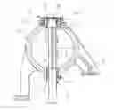
FIG. 1 shows a valve device according to the invention, in section.
DETAILED DESCRIPTION OF THE PRESENTLY PREFERRED EMBODIMENTS
The valve device in FIG. 1 is composed of a housing 1 and of a flow duct 2, which runs in the housing 1 and in which a valve flap 3 is fastened to a shaft 4 arranged perpendicular to the flow direction. The shaft 4 is mounted rotatably in the housing 1. For the bearing arrangement, the housing has bores 5, 5′ in which bearing bushings 6, 6′ are arranged. The housing 1 can be connected to other components by webs 7, 7′. In the illustration shown, the fixed bearing is arranged in the bore 5. For this purpose, the bore 5 has a base 8, which has an opening 9 through which the shaft 4 extends as far as a drive (not illustrated). The bearing bushing 6 bears against the base 8, the bearing bushing being delimited, at its opposite side, by a collar 10 of the shaft 4. The bore 5′ receives the bearing bushing 6′ without restricting the axial movement of the bearing bushing 6′. A collar 11 of the shaft 4 bears against the bearing bushing 6′ at the flap side. The bearing bushing 6′ is arranged in the bore 5′ so as to project partially out of the bore 5′. A spring pot 12 surrounds the housing part that surrounds the bore 5′. The spring pot 12 is composed of a base 13, which bears against the bearing bushing 6′, and of a radially undulating shell surface 14. The spring pot 12 bears, by way of a flange 15, against the housing 1. The structure of the undulating shell surface 14 generates a spring force, such that the base 13 generates a force in the direction of the bearing bushing 6′, which leads to a preload of the floating bearing, thus giving rise to a bearing arrangement, which is free from axial play. For sealing of the bore 5′, and for the generation of the spring force, the flange 15 is welded to the housing 1. Aside from the illustrated embodiment, it is also possible for the floating bearing and fixed bearing to be interchanged, such that the floating bearing with the spring pot is then arranged on the side facing toward the drive of the shaft. In this variant, the base of the spring pot likewise bears against the bearing bushing and is interrupted only for the leadthrough of the shaft.
Thus, while there have been shown and described and pointed out fundamental novel features of the invention as applied to a preferred embodiment thereof, it will be understood that various omissions and substitutions and changes in the form and details of the devices illustrated, and in their operation, may be made by those skilled in the art without departing from the spirit of the invention. For example, it is expressly intended that all combinations of those elements and/or method steps which perform substantially the same function in substantially the same way to achieve the same results are within the scope of the invention. Moreover, it should be recognized that structures and/or elements and/or method steps shown and/or described in connection with any disclosed form or embodiment of the invention may be incorporated in any other disclosed or described or suggested form or embodiment as a general matter of design choice. It is the intention, therefore, to be limited only as indicated by the scope of the claims appended hereto.
Claims
1-5. (canceled)
6. A valve device comprising:
a housing;
a flow duct arranged in the housing;
a shaft mounted rotatably in the housing, the shaft being arranged perpendicular to a flow direction in the flow duct;
a valve flap arranged in the housing, the valve flap being fastened to the shaft;
a floating bearing (5′, 6′); and
a spring pot (12) surrounding the floating bearing, the spring pot (12) having:
a base (13) that bears against a bearing bushing (6′) of the floating bearing, and a shell surface (14) having a radially undulating shape.
7. The valve device as claimed in claim 6, further comprising a bore (5′) of the floating bearing surrounded by a part of the housing, wherein the spring pot (12) surrounds the part of the housing part that surrounds the bore (5′).
8. The valve device as claimed in claim 6, wherein the spring pot (12) comprises metal.
9. The valve device as claimed in claim 6, wherein the spring pot (12) has a flange (15) connected to the housing (1).
10. The valve device as claimed in claim 9, wherein the flange (15) is welded or screwed to the housing (1).
Images & Drawings included:
Sources:
- United States Patent and Trademark Office - verify current appl. status at the USPTO↗
Similar patent applications:
- » 20210239222
Valve device, method for replacing valve body unit of valve device, and valve device assembly method - » 20100059130
Directional control valve device and directional control valve device block having directional control valve devices - » 20130020790
Valve device and airbag comprising such a valve device, and method for operating such a valve device - » 20230258376
Valve Device for a Heat-Pump System, Heat-Pump-System Having Such a Valve Device, and Building Having Such a Valve Device or Such a Heat-Pump System - » 20210293344
ELECTROMAGNETIC ACTUATING DEVICE PARTICULARLY FOR OPENING AND CLOSING A VALVE DEVICE, VALVE DEVICE HAVING AN ACTUATING DEVICE OF THIS KIND, CONTROLLABLE VIBRATION DAMPER COMPRISING AN ACTUATING DEVICE OF THIS KIND AND MOTOR VEHICLE HAVING A VIBRATION DAMPER OF THIS KIND - » 20190136880
Method for operating a valve device, valve device and data storage medium with a computer program - » 20240154222
HEAT SEALING FILM, VALVE DEVICE WITH HEAT SEALING FILM, ELECTRICITY STORAGE DEVICE, VALVE STRUCTURE FOR ELECTRICITY STORAGE DEVICE, AND METHOD FOR MANUFACTURING VALVE STRUCTURE FOR ELECTRICITY STORAGE DEVICE - » 20130263649
VALVE, DEVICE COMPRISING A VALVE, USE OF THE VALVE IN THE DEVICE, MICROPUMP COMPRISING A VALVE, ATOMIZATION SYSTEM COMPRISING A VALVE, AND METERING/MIXING DEVICE COMPRISING A VALVE - » 20070151611
Valve device and valve disk for a valve device - » 20150053875
Closure element for a valve device and valve device
Recent applications in this class:
- » 20240159317 2024-05-16
Wear surface sleeve press fit onto a shaft in a high temperature air valve application - » 20240052930 2024-02-15
BUTTERFLY VALVE ASSEMBLY, IN PARTICULAR FOR A GAS FLOW IN A FUEL CELL SYSTEM - » 20240052929 2024-02-15
Butterfly valve assembly, in particular for a gas flow in a fuel cell system - » 20220196154 2022-06-23
BUTTERFLY VALVE WITH VIBRATION RESISTANT MOUNT - » 20220074500 2022-03-10
Butterfly valve with vibration resistant mount - » 20210172531 2021-06-10
Butterfly valve - » 20190277408 2019-09-12
Butterfly valve - » 20180142790 2018-05-24
Mounting of a flap valve shaft - » 20170363213 2017-12-21
Valve device in a motor vehicle - » 20170159828 2017-06-08
FLUID CIRCULATION VALVE, IN PARTICULAR FOR A MOTOR VEHICLE, WITH THRUST WASHER AND METHOD FOR MANUFACTURING SUCH A VALVE
Recent applications for this Assignee:
- » 20250006057 2025-01-02
VEHICLE-EXIT ASSIST APPARATUS - » 20240312120 2024-09-19
METHOD AND DEVICE FOR PROVIDING A VISUALIZATION OF A VEHICLE, AND VEHICLE - » 20240295913 2024-09-05
ELECTRONIC DEVICE AND METHOD OF RESPONDING TO A TRIGGER TO WAKE UP - » 20240126118 2024-04-18
Display system and method for operating a display system - » 20240103589 2024-03-28
Frame for an electro-optical display and electro-optical display having a frame - » 20240103348 2024-03-28
Device for securing an optical device - » 20240103153 2024-03-28
Distance measuring system - » 20240100956 2024-03-28
Control unit circuit for a motor vehicle, motor vehicle and operating method for the control unit circuit - » 20240053161 2024-02-15
Method for predicting a velocity profile of a vehicle - » 20230356682 2023-11-09
Method for adapting a triggering algorithm of a personal restraint device and control device for adapting a triggering algorithm of a personal restaint device