Wide view light reflector
US20140368940A1
2014-12-18
13/917,003
2013-06-13
✅ Patent granted
US 8,988,676 B2
2015-03-24
-
-
Charlie Y Peng
2033-07-17
Abstract:
This apparatus provides a method to enable a borescope to see inside a bore with a brighter image and a less obstructed view. This removable apparatus is essentially an extended coil spring that grips over the forward end of a borescope shaft by compression. The opposite end of this apparatus is connected in the same manner to an opposing light reflector by constricting over the outside surface of a light reflector. As a borescope enters the bore, it emits light forward that is reflected by the light reflector rearward against the viewing surface inside the bore. This apparatus connects the borescope to an opposing reflective surface with an extended thin wire that is partially in view of the borescope, providing minimal obstruction of the viewing area that is seen by the borescope. This apparatus also provides a minimal increase to the outside diameter of the borescope allowing it to fit inside a smaller bore.
Assignee:
- Larry A. Willis 1 🇺🇸 Casselberry, FL, United States
Applicant:
Interested in similar patents?
Get notified when new applications in this technology area are published.
Classification:
G02B23/24 IPC
Telescopes, e.g. binoculars; Periscopes; Instruments for viewing the inside of hollow bodies; Viewfinders; Optical aiming or sighting devices Instruments or systems for viewing the inside of hollow bodies, e.g. fibrescopes
G02B23/2476 » CPC main
Telescopes, e.g. binoculars; Periscopes; Instruments for viewing the inside of hollow bodies; Viewfinders; Optical aiming or sighting devices; Instruments or systems for viewing the inside of hollow bodies, e.g. fibrescopes Non-optical details, e.g. housings, mountings, supports
H04N5/225 IPC
Details of television systems; Studio circuitry; Studio devices; Studio equipment ; Cameras comprising an electronic image sensor, e.g. digital cameras, video cameras, TV cameras, video cameras, camcorders, webcams, camera modules for embedding in other devices, e.g. mobile phones, computers or vehicles Television cameras ; Cameras comprising an electronic image sensor, e.g. digital cameras, video cameras, camcorders, webcams, camera modules specially adapted for being embedded in other devices, e.g. mobile phones, computers or vehicles
H04N2005/2255 » CPC further
Details of television systems; Studio circuitry; Studio devices; Studio equipment ; Cameras comprising an electronic image sensor, e.g. digital cameras, video cameras, TV cameras, video cameras, camcorders, webcams, camera modules for embedding in other devices, e.g. mobile phones, computers or vehicles; Television cameras ; Cameras comprising an electronic image sensor, e.g. digital cameras, video cameras, camcorders, webcams, camera modules specially adapted for being embedded in other devices, e.g. mobile phones, computers or vehicles for picking-up images in sites, inaccessible due to their dimensions or hazardous conditions, e.g. endoscope, borescope
G01N21/00 IPC
Investigating or analysing materials by the use of optical means, i.e. using sub-millimetre waves, infrared, visible or ultraviolet light
Description
BACKGROUND OF INVENTION
1. Field of the Invention
This invention relates in general to an apparatus that provides a method for assisting a borescope to view inside a bore. This includes a light reflector and a means of attaching to a borescope. It is also suitable for providing a brighter and less obstructed view inside a bore.
2. Discussion of the Related Art
There are several different uses for this device. One example is where hunters and shooters need to examine inside the barrel of their firearm for defects and to see if it is sufficiently clean. Visual inspection is required during the cleaning process to ensure maximum accuracy. One long existing problem is getting a clear view deep inside the barrel. One of the most important advantages of this device is to view inside a bore by providing a brighter and a less obstructed view. This method of attaching a reflective surface with a thin extended compression spring makes it possible to fit inside a smaller diameter bore to see a brighter and less obstructed view of the interior surface of the bore.
SUMMARY OF INVENTION
This removable apparatus provides a method for connecting a light reflector to a borescope for reflecting light against the viewing surface of the bore. This apparatus adds minimal outside diameter of the borescope thereby allowing the borescope and light reflector to fit inside the smallest bore possible. The center of this apparatus is a straight, long, thin, integral wire that connects a light reflector to the borescope while provides a minimal obstruction of view inside the bore. This apparatus attaches a borescope to a light reflector using spring compression to allow adjustable in-line positioning of different type reflectors.
DESCRIPTION OF THE DRAWINGS
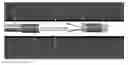
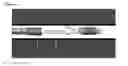
FIG. 1 is a view showing a borescope, a extended compression spring, and a light reflector.
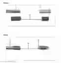
FIG. 2 is a view showing a light reflector connected to a borescope by an extended compression spring.
FIG. 3 is a view showing a borescope emitting light toward the reflector and reflecting rearward to illuminate the inside surface of a bore.
DETAILED DESCRIPTION OF THE PREFERRED EMBODIMENTS
Referring now to the drawings, which are for the purpose of illustrating the preferred embodiment of the invention and not for the purpose of limiting the same, the drawing FIG. 1 shows an enlarged view of a borescope and individual parts of the complete Wide View Light Reflector. This includes the extended compression spring 20 and the light reflector 30. FIG. 2 shows an enlarged view of the light reflector 30 that is connected to a borescope 10 by an extended compression spring 20. The borescope 10 is pushed inside the compression spring 20 until it is securely gripped and positioned in an opposing alignment with the light reflector 30. The Light Reflector 30 is pushed into the opposite end of the compression spring 20 until it is securely gripped and positioned in opposing alignment with the borescope 10. For clarification in describing the purpose and function of the Wide View Light Reflector FIG. 3 shows light being emitted from a borescope 10 to the surface of the light reflector 30 and reflected back toward the viewable inside surface of the bore 40. The light reflector 30 is secured in place by the compression of the extended compression spring 20 and can be adjusted front to rear providing the optimal position for reflecting light back to the bore surface 40 thereby illuminating the view of the borescope 10.
Claims
What is claimed is:1. An apparatus for providing a borescope with a brighter and less obstructed view, comprising:
A removable coil spring capable of connecting a borescope suitable to facilitate viewing inside a bore to an opposing light reflector by means of a compression spring gripping both objects and positioned to reflect light inside a bore by providing a minimal visible connection using an extended thin wire thereby providing less obstruction to the viewing surface.
2. The apparatus of claim 1 attaches said borescope to said light reflector by said thin compression spring adds minimal outside diameter to said borescope allowing said borescope and said light reflector to therefore fit inside said bore with a smaller inside diameter.
3. The apparatus of claim 1 is attached to said borescope provides a method to connect said light reflector allowing said reflector to be positioned at various distances from said borescope.
4. The apparatus of claim 1 is attached to said borescope provides a method to connect different types of said light reflecting surfaces.
Images & Drawings included:
Sources:
- United States Patent and Trademark Office - verify current appl. status at the USPTO↗
Recent applications in this class:
- » 20250291173 2025-09-18
EXTENSION TOOL - » 20250284113 2025-09-11
USE OF MEMORIZED ALLOY FOR INACCESSIBLE LOCATION - » 20250208402 2025-06-26
HOLDING DEVICE, ARRANGEMENT AND METHOD FOR HOLDING AN ENDOSCOPE OR PART OF AN ENDOSCOPE - » 20250116855 2025-04-10
Using Force Sensing to Prevent Borescope Damage - » 20240280799 2024-08-22
CONTROL MODULE FOR INSPECTION TOOL - » 20240134181 2024-04-25
MEDICAL BORESCOPES AND RELATED TIP ASSEMBLIES - » 20240118531 2024-04-11
ENDOSCOPE - » 20230393382 2023-12-07
ENDOSCOPE - » 20230152570 2023-05-18
SWITCH BUTTON FOR AN ENDOSCOPE - » 20220244522 2022-08-04
Optical coupling, endoscopy arrangement and corresponding use