Non-spill valve
US20150020906A1
2015-01-22
14/361,598
2012-11-28
✅ Patent granted
US 9,326,916 B2
2016-05-03
WO; PCT/GB2012/052931; 20121128
WO; WO2013/079932; 20130606
Jeffrey Allen | Jennifer Castriotta
MacMillan, Sobanski & Todd, LLC
2032-11-28
Abstract:
A non-spill valve for the neck of a liquid container. The invention also relates to a non-spill valve for the nipple of a feeding bottle, to a teat which is provided with such a nipple and to a feeding bottle which has such a teat. The valve has a tube which is open at one end and upstands from a support, which is complementary with interior element so that it forms a partition and permits the passage of liquid from an aperture in the support only into the tube interior, wherein the other end of the tube is closed except for an incision which separates the closed end from an adjoining side wall portion. The incision defines a flap that can permit liquid to reach from the tube interior to the mouth of the neck or spout or nipple.
Assignee:
- BB IPR Limited 2 🇬🇧 Middlesex, United Kingdom
Applicant:
Interested in similar patents?
Get notified when new applications in this technology area are published.
Classification:
A61J11/002 » CPC main
Teats having means for regulating the flow rate by using valves
A47G19/2272 » CPC further
Table service; Drinking vessels or saucers used for table service; Drinking glasses or vessels; Means for facilitating drinking, e.g. for infants or invalids from drinking glasses or cups comprising lids or covers
B65D47/06 » CPC further
Closures with filling and discharging, or with discharging, devices; Closures with discharging devices other than pumps with pouring spouts or tubes; with discharge nozzles or passages
B65D47/2031 » CPC further
Closures with filling and discharging, or with discharging, devices; Closures with discharging devices other than pumps comprising hand-operated members for controlling discharge comprising a valve or like element which is opened or closed by deformation of the container or closure the element being formed by a slit, narrow opening or constrictable spout, the size of the outlet passage being able to be varied by increasing or decreasing the pressure
F16K15/14 » CPC further
Check valves with flexible valve members
A61M2039/242 » CPC further
Tubes, tube connectors, tube couplings, valves, access sites or the like, specially adapted for medical use; Valves or arrangement of valves; Check- or non-return valves designed to open when a predetermined pressure or flow rate has been reached, e.g. check valve actuated by fluid
A61M2039/244 » CPC further
Tubes, tube connectors, tube couplings, valves, access sites or the like, specially adapted for medical use; Valves or arrangement of valves; Check- or non-return valves; Valve comprising a resilient or deformable element, e.g. flap valve, deformable disc Hinged closure member, e.g. flap valve
A61M2039/2433 » CPC further
Tubes, tube connectors, tube couplings, valves, access sites or the like, specially adapted for medical use; Valves or arrangement of valves; Check- or non-return valves Valve comprising a resilient or deformable element, e.g. flap valve, deformable disc
Y10T137/7879 » CPC further
Fluid handling; Line condition change responsive valves; Direct response valves [i.e., check valve type] Resilient material valve
A61M39/24 IPC
Tubes, tube connectors, tube couplings, valves, access sites or the like, specially adapted for medical use; Valves or arrangement of valves Check- or non-return valves
A61J11/00 IPC
Teats
B65D47/20 IPC
Closures with filling and discharging, or with discharging, devices; Closures with discharging devices other than pumps comprising hand-operated members for controlling discharge
A47G19/22 IPC
Table service Drinking vessels or saucers used for table service
Description
The invention relates to a non-spill valve for the neck or spout of a liquid container, to a cap for the container in which the cap is provided with such a neck or spout and to a container which is fitted with such a cap, for example a so-called non-spill drinking cup for toddlers and incapacitated persons. The invention also relates to a non-spill valve for the nipple of a feeding bottle for babies and invalids, to a teat for the bottle in which the teat is provided with such a nipple and to a feeding bottle which is fitted with such a teat.
According to one aspect of the invention, the non-spill valve comprises a flexible tube which is open at one end and upstands from an apertured support of which the aperture is in registry with and of the same size as the open end of the tube, the support having a shape which is complementary with the interior of the neck or spout or nipple so that it forms a partition in the neck or spout or nipple of the container or feeding bottle and permits the passage of liquid from the aperture in the support only into the tube interior, wherein the other end of the tube is closed except for an incision which separates the closed end from an adjoining side wall portion of the tube, the incision being continued along said side wall portion up to a distance short of the support so as to define a flap which is hinged to the support wall and lies against the part from which it is severed but can flex under suction applied to the neck or spout or nipple and thereby permit liquid to reach from the tube interior to the mouth of the neck or spout or nipple.
Preferably, the material of the flexible tube is silicone and is moulded in one piece with its support. The support will be provided with at least one ridge or rib adapted to interengage with a groove or shoulder enabling the support and tube to be removably fixed in position within the neck or spout or nipple.
According to another aspect of the invention, the aforementioned spout or neck or nipple is likewise of flexible plastics material and moulded in one piece with at least one such non-spill flap valve and its support. If two or more flap valves are provided, there can be a single support with a corresponding number of complementary apertures for the tubes of the valves. Further, instead of being moulded in one piece with the cap of a container or with the teat of a feeding bottle, the or each tube may be moulded together with mounting means for connecting the spout or neck or nipple to a cap or teat of the container or feeding bottle.
Examples of the invention will now be described with reference to the accompanying drawings wherein:
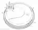
FIG. 1 is a diagrammatic pictorial view of a flap valve according to the invention;
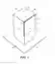
FIG. 2 is a pictorial view of part of a cap with spout for a non-spill mug, the spout of the cap being fitted with two flap valves;
FIG. 3 is cross-sectional view of the FIG. 2 spout with the two non-spill valves moulded into it;
FIGS. 4 and 5 are cross-sectional views similar to FIG. 3 and showing the flap valves of a modified spout respectively in the closed and open conditions;
FIG. 6 is a fragmentary side elevation of a drinking cup or mug fitted with the FIG. 2 closure cap, and
FIG. 7 is a fragmentary cross-section of the mug taken on the line VII-VII in FIG. 6.
Referring to FIG. 1, the flap valve comprises a tube 1 of substantially rectangular cross-section open at its lower end and closed at the top by a wall 2. The tube sides are defined by opposite side walls 3 and 3g and opposite side walls 4 and 4a.
The open lower end of the tube 1 is in registry with and of the same size as a hole 6a in a support 6 from which the tube 1 upstands and which is preferably moulded in one piece with the tube 1 from a flexible plastics material such as silicone. The side wall 4 is fully separated from the top wall 2 and partially separated from the side walls 3 and 3a by an incision 7 which stop short of the support 6 so as to define a flap 5 which is hinged to the lower part of the wall 4. By reason of the nature of the flexible silicone material, the flap 5 lies snugly against the edges of the walls 2, 3 and 3a from which it was severed.
When the valve of FIG. 1 is inserted in a spout or neck or nipple of a liquid container or nipple of a feeding bottle, or if it is moulded in one piece therewith, so that the closed top end of the tube 1 is directed towards the mouth of the spout or neck or towards the hole in the teat and the open lower end communicates with the liquid contents of the container or bottle through the aperture 6a in the support 6, liquid is prevented from reaching the mouth of the spout or neck or nipple by the tube being held shut by the flap 5. Consequently, no liquid can reach the mouth of the spout or neck or nipple. However, if vacuum is applied to the exterior of the tube wall 4 by suction being applied by the user, the flexibility of the silicone material will permit the flap portion 5 of the wall 4 to flex away from the walls 2, 3 and 3a of the tube to leave a gap through which liquid is sucked up from the container to the mouth of the spout or neck. When the user stops sucking, the memory characteristic of the silicone material of the flap causes it to flex back to the closing position against the walls 2, 3 and 3a.
Referring to FIG. 2, this pictorial view illustrates part of a closure cap for a non-spill mug having an elliptical integral spout 8 of silicone material moulded to a silicone closure portion 9 which is part of the closure cap. The spout 8 contains two flap valves within the nozzle constructed in the manner described with reference to the FIG. 1 construction. Of course in this case, the support 6 which is shown in FIG. 1, not visible in FIG. 2 and shown in broken lines in: the: cross-section of FIG. 3 would be of elliptical shape and contain two apertures each to communicate with the lower open end of each tube.
The closure portion 9 is circular and at its circumference contains a shoulder 11 and groove 12 for inter-engagement with a less flexible or non-flexible ring shown in FIGS. 6 and 7 and having an internally screw threaded circular skirt 13 for engaging an externally screwthreaded neck 14 of a mug 16 in conventional manner. The silicone closure portion 9 therefore has its shoulder 11 sealingly trapped between the neck 13 of the mug 16 and the ring 13 of the closure cap.
The cross-sectional views of FIGS. 4 and 5 of a modified spout have been included to show that the flaps 5 of the two valves are in the closed position of FIG. 4 when the user is not sucking on the spout 8 but will flex to the open position of FIG. 5 when the user of the mug sucks on the mouth of the spout 8.
It will be evident that the invention is applicable not only to the spouts of non-spill mugs but also other drinking vessels and in particular to the removable teats of feeding bottles.
Claims
1-15. (canceled)
16. A non-spill valve for a neck and spout of a liquid container, comprising:
a flexible tube which is open at a first end and upstands from an apertured support of which an aperture is in registry with and of the same size as the first open end of the tube, the support having a shape which is complementary with an interior of the neck and spout so that it forms a partition in the neck and spout of the container and permits the passage of liquid from the aperture in the support into the tube interior, wherein a second end of the tube is closed except for an incision which separates the second end from an adjoining side wall portion of the tube, the incision continued along the side wall portion up to a distance short of the support to define a flap which is hinged to the support wall and lies against a part from which it is severed but can flex under suction applied to the neck and spout and thereby permit liquid to reach from the tube interior to a mouth of the neck or spout.
17. A valve according to claim 16, wherein the material of the flexible tube is silicone and is moulded in one piece with its support.
18. A valve according to claim 16, wherein the support is provided with at least one ridge adapted to interengage with a groove and shoulder enabling the support and tube to be removably fixed in position within the neck and spout.
19. A valve according to claim 17, wherein the spout and neck is flexible silicone material and moulded in one piece with at least one flap and its support.
20. A valve according to claim 18, comprising two or more of said flaps, a single said support and, in the support, a corresponding number of complementary apertures for the tubes.
21. A valve according to claim 16, wherein the tube is moulded together with mounting means for connecting the spout and neck to a cap of the container.
22. A non-spill valve for a nipple of a feeding bottle, comprising:
a flexible tube which is open at first and upstands from an apertured support of which the aperture is in registry with and of the same size as the first open end of the tube, the support having a shape which is complementary with the interior of the nipple so that it forms a partition in the nipple of the feeding bottle and permits the passage of liquid from the aperture in the support only into the tube interior, wherein the second end of the tube is closed except for an incision which separates the second closed end from an adjoining side wall portion of the tube, the incision continued along said side wall portion up to a distance short of the support to define a flap which is hinged to the support wall and lies against the part from which it is severed but can flex under suction applied to the nipple and thereby permit liquid to reach from the tube interior to a mouth of the nipple.
23. A valve according to claim 22, wherein a material of the flexible tube is silicone and is moulded in one piece with its support.
24. A valve according to claim 22, wherein the support is provided with at least one ridge adapted to interengage with a groove and shoulder enabling the support and tube to be removably fixed in position within the nipple.
25. A valve according to claim 24, wherein the nipple is of flexible silicone material and moulded in one piece with at least one such flap and its support.
26. A valve according to claim 22, comprising two or more of said flaps, a single said support and, in the support, a corresponding number of complementary apertures for the tubes.
27. A valve according to claim 22, wherein the tube is moulded together with mounting means for connecting the nipple to a teat of the feeling bottle.
Images & Drawings included:


Sources:
- United States Patent and Trademark Office - verify current appl. status at the USPTO↗
Similar patent applications:
- » 10406744
Valve for non-spill cup - » 20200383505
Non-spill cup and fluid control valve system with all round drinking rim
Recent applications in this class:
- » 20250099339 2025-03-27
Baby Bottle with Ribs on Inner Surface of Nipple - » 20240180787 2024-06-06
UNIDIRECTIONAL VALVE FOR PRESURIZED CONTAINERS - » 20240065942 2024-02-29
FLOW CONTROL VALVE FOR INFANT FEEDING DEVICE - » 20240065941 2024-02-29
FLOW CONTROL VALVE FOR INFANT FEEDING DEVICE - » 20230346648 2023-11-02
TEAT AND DRINKING CONTAINER HAVING THE TEAT - » 20230181427 2023-06-15
FLOW CONTROL SYSTEM FOR A BABY BOTTLE - » 20220117852 2022-04-21
Teat for use with a container for containing a fluid - » 20220110834 2022-04-14
TEAT FOR USE WITH A CONTAINER FOR CONTAINING LIQUID - » 20220040045 2022-02-10
Baby feeding bottle - » 20210283020 2021-09-16
Unidirectional valve for pressurized containers
Recent applications for this Assignee:
- » 20120112023 2012-05-10
SUCTION FIXING