QUARTER TURN TORQUE ANCHOR AND CATCHER
US20150041153A1
2015-02-12
14/311,322
2014-06-22
Abstract:
A tubing anchor for anchoring and catching well equipment in a well conduit to arrest movement in both longitudinal directions and rotation in a first direction. A mandrel connected to the equipment has in one embodiment C or reverse C-shaped grooves when viewed in front elevation for slideably receiving respective pins from a drag body on the mandrel. A slip retainer on the mandrel houses slips for selectively engaging and disengaging the conduit. An initial pull of the mandrel causes the pins to move the drag body toward the slip retainer driving the slips outward to grip the conduit. Rotation of the mandrel in the first direction sets the anchor to arrest movement. Further pulling and a reversed turn of the mandrel maintains the set position. A spring biases the slips outward to maintain their set to catch the well equipment in the event of a break in the string above the anchor.
Inventors:
- Edward L. Moore 5 🇨🇦 Calgary, Canada
- CHRISTOPHER S. McARTHUR 2 🇨🇦 CALGARY, Canada
- JASEN L. HOFFMAN 2 🇨🇦 AIRDRIE, Canada
- KEVIN D. KELM 2 🇨🇦 EDMONTON, Canada
Interested in similar patents?
Get notified when new applications in this technology area are published.
Classification:
E21B17/021 » CPC further
Drilling rods or pipes; Flexible drill strings; Kellies; Drill collars; Sucker rods; Casings Cables; ; Tubings; Couplings; joints Devices for subsurface connecting or disconnecting by rotation
E21B19/16 » CPC main
Handling rods, casings, tubes or the like outside the borehole, e.g. in the derrick; Apparatus for feeding the rods or cables Connecting or disconnecting pipe couplings or joints
E21B17/02 IPC
Drilling rods or pipes; Flexible drill strings; Kellies; Drill collars; Sucker rods; Casings Cables; ; Tubings Couplings; joints
Description
CROSS REFERENCE TO RELATED APPLICATIONS
This application claims priority from Canadian Patent Application No. ______ filed Jun. 14, 2014 entitled Quarter Turn Torque Anchor and Catcher. This application is a continuation in-part of U.S. patent application Ser. No. 13/716,075 filed ______ and entitled Quarter Turn Tension Torque Anchor.
FIELD OF THE INVENTION
The present invention relates to tools for oil and gas wells generally, including wells accessing heavy crude, and in particular relates to a ¼ turn tension torque or tubing anchor (collectively herein a tubing anchor) and catcher for anchoring from rotation and linear movement, and catching well equipment, such as a progressive cavity or rod pump, and related tubing string in a well conduit.
BACKGROUND OF THE INVENTION
Known tubing anchors, also referred to as anchor catchers, use either a combination of right and left hand threads, or are limited to one thread orientation.
Examples of such tubing anchors are shown in U.S. Pat. No. 3,077,933 to Bigelow and in Canadian patent no. 933,089 to Conrad. Disadvantages of such tubing anchors include the expense of manufacturing the threaded portions, and the stop pins are vulnerable to breakage during use.
Another type of tubing anchor shown in U.S. Pat. No. 5,771,969 and corresponding Canadian patent no. 2,160,647 to Garay avoids the aforementioned threads and instead uses a helical bearing to transform rotational movement into linear movement for setting and unsetting the tubing anchor. The helical bearing also accommodates shear pins for secondary unsetting if required. The use of one component, namely the helical bearing, to perform several functions has the advantage over the previous prior art of being less expensive to manufacture and less susceptible to breakage.
However, there is a need for a tubing anchor that further improves on these prior designs. In particular, there is a need for a tubing anchor that avoids the prior art threads and helical bearings that require one or more full (i.e. 360 degree) rotations of the tubing anchor's mandrel to either set or unset the tubing anchor. The tubing anchor should not need to translate rotational movement into linear movement to engage the anchor slips with the well conduit, but rather should directly transfer a short longitudinal movement of the mandrel to extend the slips into gripping engagement with the well conduit. The tubing anchor should require only a limited rotation, such as a quarter turn, of the mandrel in a first direction to set the tubing anchor, and to help maintain the anchor in the set position by merely pulling tension on the mandrel via the tubing string. One or more tracks in the mandrel, each formed by a groove having joined longitudinal and transverse arms, should guide a corresponding drive pin to achieve the desired longitudinal and rotational movements. The groove's arms should be relatively short to reduce both manufacturing costs and the risk of debris entering the groove to interfere with proper operation. The tubing anchor should have a secondary unsetting capability where release is achieved by merely pulling the mandrel at a predetermined force to sever certain fasteners mounted to the mandrel.
SUMMARY OF THE PRESENT INVENTION
A tubing anchor for anchoring well equipment in a well conduit to arrest movement in both longitudinal directions and rotation in a first direction includes:
-
- a mandrel connected to said well equipment;
- a first cone element slidably mounted to said mandrel and having a first conical surface;
- a drag body slidably mounted on said mandrel, housing a drag or a drag means for contacting said well conduit, and having a second cone element having a second conical surface;
- a slip retainer mounted on said mandrel housing at least one slip, each slip having an inner surface, and an opposed outer surface for gripping said well conduit, and a biasing device or biasing means for urging said slip inwardly toward said mandrel and away from said well conduit;
- at least one pin connected to said drag body and a portion of said pin protruding toward said mandrel; and,
- said mandrel having at least one groove for slideably receiving said protruding portion of said pin in sliding relation on a corresponding groove;
and wherein said groove has at least one longitudinally extending portion and at least one lateraly extending portion contiguous with and extending laterally of said at least one longitudinally extending portion, wherein said at least one longitudinally extending portion extends along said mandrel and said at least one laterally extending portion extends at least partially around said mandrel, - wherein said pulling of said mandrel translates said pin to an end of said at least one longitudinally extending portion of said groove so as to said cause said pin, and in turn said second conical surface of said drag body, to move toward said first cone element,
and further comprising at least one spring configured to resiliently urge said first cone element towards said second conical surface to thereby provide a catcher, wherein a release of said tension caused by a break in said well equipment drives said spring, and thereby said first cone element, so as to engage said inner surface of each said slip and to said drive each said slip outward to said grip the well conduit.
In the preferred embodiment the at least one longitudinally extending portion includes laterally spaced apart first and second longitudinally extending portions, and the at least one laterally extending portion includes longitudinally spaced apart first and second laterally extending portions interleaved with said first and second longitudinally extending portions, so as to provide a sequence in said groove of said first longitudinally extending portion, said first laterally extending portion, said second longitudinally extending portion, and said second laterally extending portion. Also in the preferred embodiment, the first and second laterally extending portions of said groove require, for said portion of said pin to follow along said groove, that said mandrel be turned in reverse first and second corresponding directions about said axis of rotation. By way of example, said at least one laterally extending portion extends at least substantially a quarter of a circumferential distance around said mandrel; that is, substantially a quarter turn of the mandrel.
When said mandrel is viewed in vertical elevation, the groove is shaped as substantially a C-shape or a reversed C-shape depending on the vertical orientation of the mandrel when so viewed, and direction of turn of the pump in the string. Thus, if the pump in the string turns to the left, when viewed from above, the mandrel is turned clockwise to the right, then left to move the pin along the groove. Unset or release is then a right turn of the mandrel. If the pump turns to the right, the mandrel is turned left then right, that is, in mirror image, and the release is a turn to the left.
In embodiments with a plurality of drive pins, a corresponding a plurality of said grooves are radially spaced around the circumference of said mandrel
In one embodiment the, at least one pin is a drive pin adapted to shear off to provide a secondary release when said mandrel is pulled in tension in excess of a failure shear resistance of said at least one pin. In other embodiments, separate shear pins are provided as a secondary release.
In a method of anchoring well equipment in a well conduit to arrest movement in both longitudinal directions and rotation in a first direction, and to allow rotation in an opposite second direction, using a tubing anchor and catcher having:
-
- a mandrel connected to said well equipment, said mandrel having a longitudinal axis of rotation;
- a first cone element slidably mounted on said mandrel, said first cone element having a first conical surface;
- a drag body slidably mounted on said mandrel, a drag coupled to said drag body and sized to drag against said well conduit, said drag body having a second cone element having a second conical surface;
- a slip retainer mounted on said mandrel, said slip retainer housing at least one slip, each slip having an inner surface, and an opposed outer surface for gripping said well conduit, and a biasing device urging each slip inwardly toward said mandrel and away from said well conduit;
- at least one pin connected to said drag body and having a portion of said pin protruding toward said mandrel; and,
- said mandrel having at least one groove slideably receiving said protruding portion of said pin in sliding relation in said groove;
- wherein a tension applied to said well equipment causes an initial pulling on said mandrel which causes said pin, and in turn said second cone element to move toward said first cone element so that said second conical surface of said drag body contacts said inner surface of each said slips and urges said inner surface of each said slip to contact said first conical surface of said first cone element so that said first and second conical surfaces drive each said slip outward so that said outer surfaces of each said slip grips said well conduit,
and wherein said groove has at least one longitudinally extending portion and at least one lateraly extending portion contiguous with and extending laterally of said at least one longitudinally extending portion, wherein said at least one longitudinally extending portion extends along said mandrel and said at least one laterally extending portion extends at least partially around said mandrel, - wherein said pulling of said mandrel translates said pin to an end of said at least one longitudinally extending portion of said groove so as to said cause said pin, and in turn said second conical surface of said drag body, to move toward said first cone element,
- and further comprising at least one spring configured to resiliently urge said first cone element towards said second conical surface to thereby provide a catcher, wherein, a release of said tension caused by a break in said well equipment drives said spring, and thereby said first cone element, so as to engage said inner surface of each said slip and drive each said slip outward to said grip said well conduit,
wherein said at least one longitudinally extending portion includes laterally spaced apart first and second longitudinally extending portions, and wherein said at least one laterally extending portion includes longitudinally spaced apart first and second laterally extending portions interleaved with said first and second longitudinally extending portions, so as to provide a sequence in said groove of said first longitudinally extending portion, said first laterally extending portion, said second longitudinally extending portion, and said second laterally extending portion,
wherein said first and second laterally extending portions of said groove require, for said portion of said pin to follow along said groove, that said mandrel be turned in reverse first and second reverse directions about said axis of rotation,
wherein said method comprises: - exerting an initial pull on said mandrel to move said pin along said longitudinally extending portion of said groove to extend said slips to grip said well conduit; and,
- then rotating said mandrel in said first direction to move said pin along said first laterally extending portion of said groove to set said tubing anchor, then exerting a further pull on the mandrel followed by a reverse turn of said mandrel, after said rotation, so as to move said pin along said second longitudinally extending portion and said second laterally extend portion respectively to maintain said tubing anchor in said set position.
The unsetting of said tubing anchor comprises reversing the steps to extend said slips and set said anchor. A secondary unsetting of said tubing anchor comprises increasing said further pull on said mandrel until the failure shear resistance of said pins is exceeded.
BRIEF DESCRIPTION OF THE DRAWING FIGURES
Embodiments of the invention will now be described, by way of example only, with reference to the accompanying drawings, wherein:
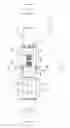
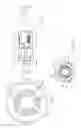
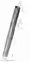
FIG. 1 is a side view of a tubing anchor according to a preferred embodiment of the present invention, shown in a run (unset) orientation;
FIG. 2 is a perspective view, in isolation, of a mandrel of the tubing anchor of FIG. 1
FIG. 3 shows the tubing anchor of FIG. 1 in a run position within a segment of well conduit shown in transparent view;
FIG. 3a is a cross-sectional view of the tubing anchor and well conduit along line 3a-3a of FIG. 3;
FIG. 4 shows the tubing anchor and well conduit of FIG 3 with a partially transparent view of a drag body housing;
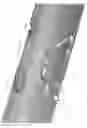
FIG. 4a is a close up view of the circle area 4a of FIG. 4;
FIG. 5 is a longitudinal section through the tubing anchor and well conduit of FIG. 3, generally along the line 5-5;
FIG. 6 shows a set position of the tubing anchor of FIG 3 in the conduit;
FIG. 6a is a cross-sectional view of the tubing anchor and well conduit along line 6a-6a of FIG. 6;
FIG. 6b is a cross-sectional view of the tubing anchor and well conduit along line 6b-6b of FIG. 6;
FIG. 7 is a longitudinal section through the tubing anchor and well conduit of FIG. 6, generally along the line 7-7;
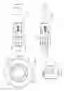
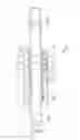
FIG. 8 is an elevation view of the tubing anchor in a further embodiment providing a catcher and improved mandrel grooves, showing a slim-hole embodiment in it's run-in position with the slips retracted;
FIG. 8a is, in cross-section, the tubing anchor and catcher of FIG. 8;
FIG. 8b is the sectional view of FIG. 8a showing the anchor in its set position with the slips extended;
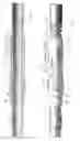
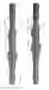
FIG. 9 is, in perspective view, the mandrel of FIG. 8 showing the improved mandrel grooves spaced around the mandrel;
FIG. 9a is an enlarged view of the mandrel grooves of FIG. 9, showing a pin from the drag body engaged in one of the grooves, in the run-in position;
FIG. 9b is the view of FIG. 9a showing the pin in the anchor set and locked position;
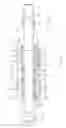
FIGS. 10a and 10b are section views of a heavy crude embodiment of the tubing anchor and catcher of FIG. 8, in the run-in and anchor set positions respectively;
FIG. 11 is an elevation view of the tubing anchor and catcher in a further embodiment proving shear pins between the slip retainer and drag blocks;
FIG. 11a is sectional view along the lines 11a-11a in FIG. 11; and,
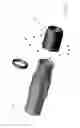
FIG. 12 is, an exploded view, the tubing anchor and catchor of FIG. 11.
FIG. 12a is an enlarged view of a portion of FIG. 12.
DESCRIPTION OF PREFERRED EMBODIMENTS
Referring first to FIGS. 1 to 5, a preferred embodiment of a tubing anchor, generally indicated by reference numeral 10, is shown inserted within a well conduit 12, such as a wellbore casing. The tubing anchor is shown in an unset, or “run-in”, orientation in which it can be run inside the well conduit on a tubing string, along with other well equipment 14, such as a safety sub, attached above and below. In particular, the well equipment is attached to a cylindrical mandrel 20 having attachment means, such as an inner threaded lower end 22 and an outer threaded upper end 24. In this embodiment, the tubing anchor is run down the well conduit on the tubing string in the direction indicated by arrow 16. It is noted, however, that terms such as “up”, “down”, “forward”, “backward” and the like used to identify certain features of the tubing anchor when placed in a well conduit is not intended to limit the tubing anchor's use or orientation. Further, when describing the invention, all terms not defined herein have their common art-recognized meaning.
The tubing anchor has a tubular drag body 40 mounted over the mandrel 20 to house a drag means in the form of multiple drag blocks 42 for spacing the tubing anchor away from the inner wall 13 of the conduit 12. In the preferred embodiment drag blocks 42, for example, three or four drag blocks 42, are generally evenly spaced circumferentially about the tubing anchor. Each drag block 42 has a drag spring 44 to urge the outer surface 46 of the drag block against the conduit's inner wall 13. Upper and lower drag retaining rings 48, 50 keep the drag blocks 42 removably mounted within the drag body 40. At least one lower cap screw 52 attaches the lower retaining ring 50 to the drag body 40. For illustrative purposes, FIG. 3a shows the use of three circumferentially staggered cap screws 52. In addition to keeping the tubing anchor spaced from the conduit, the contact of the drag block surface 46 with the conduit's inner wall 13 causes friction that urges the drag body 40 to remain stationary while the mandrel 20 moves within.
A tubular slip retainer 60, or slip cage, mounted on the mandrel 20 adjacent the drag body 40 houses a plurality of radially movable slips 62. In the drawings three slips 62 are shown generally evenly spaced about the drag body, although this is not intended to be limiting as the anchor described herein may conceivably be made to operate with only one slip 62. Each slip has an outer surface 63 with teeth for gripping the conduit wall 13 upon contact, and an inner surface with opposed outwardly inclined edges 64. A fastener in the form of a socket head cap screw 65 is fastened to the drag body 40 and is located within each of a plurality of elongate slots 66 spaced circumferentially about the slip retainer, preferably between each slip. The cap screw 65 is adapted to contact the upper and lower shoulders 68a, 68b at the ends of the slot, which form stop means to prevent the slip retainer 60, and the drag body 40, from moving off the mandrel 20.
A cone element 70 at an upper end of the slip retainer is mounted to the mandrel 20 by a plurality of circumferentially spaced fasteners in the form of shear screws 72. Screws 72 also act as shear pins to release the tubing anchor from a set position upon exertion of sufficient tension on the well equipment, as will be discussed later. The edge of the cone 70 opposite the screws 72 forms a first conical surface 74 whose inclined surface wedges under the slips 62 when the tubing anchor is moved into a set position. Likewise, an upper edge of the drag body 40 forms a second conical surface 54 whose inclined surface concurrently wedges under the slips 62 when the tubing anchor is moved into a set position. However, the first and second conical surfaces 74, 54 should not actively contact the slips in the unset position, as shown in FIG. 5. A biaser in the form of a slip spring 76 urges each slip 62 radially inwardly into the slip retainer and away from the well conduit 12 in the unset position (FIG. 5).
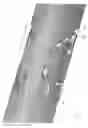
At least one groove 80 is formed in the mandrel's outer cylindrical surface 26, best seen in FIG. 2. The L-shaped groove has a first or upper arm 82 extending longitudinally with a shoulder 83 at its upper end forming a stop and an elbow 81 at its lower end. A second or lower arm 84 extends circumferentially from the elbow 81 at a generally right angle to the upper arm 82. A terminal end 86 of the lower arm forms another stop and has opposed indents 86a, 86b extending longitudinally upwardly and downwardly therefrom. The groove 80 is dimensioned (width, depth) to slidingly accommodate a protruding portion of a drive pin 88 extending therein threaded through a hole 56 in an lower part of the drag body 40 so as to slidably engage in groove 80 (FIG. 5). The lower retaining ring 50 keeps the drive pin 88 within the drag body 40 and engaged within the groove 80. In the FIG. 3a embodiment, not intended to be limiting, three sets of grooves 80 and drive pins 88 are shown generally evenly radially spaced about the mandrel.
The operation of the tubing anchor may now be described including FIGS. 6 to 7 showing the tubing anchor in the set position in the well conduit 12. In the embodiment of FIGS. 1-7 there are generally two steps for moving the mandrel 20 in a “setting direction” to the set position, and a third step to help lock, fix or maintain that set position. The first step is to initially pull the mandrel upwardly by lifting, that is, tensioning the tubing string 14 in the direction of arrow 17, so that each drive pin 88 travels downwardly along the first arm 82 of the respective groove to the elbow 81 (FIG. 2). In this embodiment that travel is relatively short, approximately 2.5 mm (about 1.0 inch). The pull on the mandrel forces the drive pins 88 to push the drag body's second conical surface 54 toward the first conical surface 74 of the cone element 70. As these two components converge, the conical surfaces contact the inner edges 64 of each slip 62 to drive the slips outwards, so that the slip's outer surface 63 contacts and bites into the well's inner wall 13. As a result, the mandrel 20 and the attached well equipment are fixed such that they can not move longitudinally in the well either up or down. At this point the second step is to turn the tubing string to the right (i.e. clockwise when looking down the tubing string in the direction of arrow 16, in this embodiment) approximately “a quarter turn” (i.e. about 90 degrees) so that each drive pin 88 travels along the lower arm 84 from the elbow 81 to the stop 86. At this point the mandrel and tubing string should be rotationally fixed in this first, or clockwise, setting direction. And finally the third step is to maintain the tubing anchor in this set orientation by continuing to pull tension on the tubing string straight up in direction 17, which should also engage the drive pin 88 with the lower indent 86b which secures the pin upon entry to aid in maintaining the set position. The drill string should be kept in tension as long as the set position is desired. This description is suited for the situation where the pump in the drill string is a rod pump. In embodiments where the pump turns to the right, for example in the case of a progressive cavity pump system, the mandrel locking movement would be reversed, that is, the mandrel is moved upwards then left and the corresponding groove shape would also be reversed, i.e., a J-shape as opposed to an L-shape, collectively referred to herein as an L-shape.
The tubing anchor is released, or unset, by reversing the above described setting procedure. The first unsetting step requires release of tension by moving the tubing string, and hence the mandrel 20, down somewhat, which should move the drive pins 88 out of the corresponding lower indents 86b to the upper indents 86a which temporarily “store” the pins on exit. The second step requires rotating the tubing string and mandrel in a second direction opposite to the setting rotation, namely turning to the left (i.e. counter-clockwise when looking down the tubing string in the direction of arrow 16, in this embodiment) approximately “a quarter turn” so that each drive pin 88 travels from the upper indents 86a along the lower arm 84 to the elbow 81. Finally, in a third step, the mandrel should be moved further down relative to the drag body so that the drive pin 88 travels up the upper arm 82 from the elbow 81 toward the stop 83. After the pin reaches this stop, continuing this mandrel movement causes the drag body 40 to move downwards, and thereby the second conical surface 54 to move away from the inner edge 64 of each slip 62. The springs 76 urge the respective slips 62 inwardly away from the well's inner wall 13, thus releasing the tubing anchor for movement longitudinally (both up and down the well) and rotationally (in the unsetting direction). This allows the tubing anchor to be moved to a different position in the well conduit 12 and be set again, or to lift the tubing anchor and remove it from the well conduit.
An alternate method of unsetting the tubing anchor is to pull tension on the tubing string to exert sufficient upward force on the mandrel 20 to shear the shear screws 72 by exceeding their maximum shear resistance. Once the shear screws 72 are sheared, the cone element 80 becomes detached from the mandrel 20 and is free to move away, namely upward, from the slips 62, allowing the springs 76 to retract the slips away from the inner surface 13 of the conduit. The torque anchor is therefore freed for removal from the well conduit 12. The maximum shear resistance may be “adjusted” by either changing the shear screws 72 to ones with a different shear value, or by altering the number of shear screws inserted into the cone element 80. For instance, in one version of the tubing anchor, twelve brass screws 72 can be employed each with about 5000 pounds (2273 kg) resistance, and their maximum shear resistance does not exceed that of the drive pins 88 to avoid damaging the pins during such secondary release of the tubing anchor.
The tubing anchor 10 is thus designed to anchor the tubing string from movement longitudinally along the well (in both directions, up and down the well) and from rotation (in the setting direction). The anchoring is achieved by simple setting and release procedures with relatively little movement of the tubing string. In this instance, setting is achieved by a small pull of the mandrel (via the tubing string) that is adequate for the drive pin 88 to travel the short distance along the longitudinal arm 82 to reach the elbow 81, and then by a small “quarter” turn of the mandrel that is adequate for the drive pin 88 to travel the short distance along the circumferential arm 82 to reach the toe 85, and finally by further pulling to engage the drive pin 88 with the lower indent 86b. The tubing anchor 10 avoids the more labourious and time consuming multiple full rotations of the mandrel that are currently required to set a tubing anchor. The relatively short L-shaped groove 80, in comparison to the multiple twists of the long threads or helical groove of other mandrels, reduces the risk of foreign objects obstructing the drive pin's travel path, and thus should improve the tubing anchor function, reliability and wear.
Also, since this anchoring is achieved by placing the tubing string in tension, there is an added benefit of ensuring that the tubing follows the rod string as closely as possible, which helps minimize rod wear.
Some further benefits are set out below.
The configuration of the tubing anchor, including the arrangement of the set screws with a given shear resistance below that of the drive pins 88, provides a relatively fast and easy secondary unsetting of the tubing anchor in case of an emergency or should a problem be encountered with the primary means of setting and unsetting via the L-shaped groove 80.
Referring to FIG. 6b, the slips 62 are configured not only to centre the tubing anchor within the well conduit 12, but radially protrude sufficiently from the slip retainer 60 to provide large by-pass spaces 78 between the tubing anchor and the conduit, creating high flow areas for fluids (eg. gas) and solids (eg. sand) to pass by the tubing anchor, and allowing coil tubing to more easily extend past the tubing anchor, than other tubing anchors. In the FIG. 6b version, for instance, by-pass spaces 78 with 1.0 inch (25.4 mm) radial clearance are created between the 4.5 inch (114.3 mm) OD of the slip retainer 60 and the 6.5 inch (165.1 mm) ID of the well conduit 12.
The configuration of the tubing anchor 10 permits capillary cable to be carried downhole via the large by-pass spaces 78 created by this novel tubing anchor design. In particular, the fact that the tubing anchor 10 is set and unset by longitudinal motion and a limited, quarter turn, permits its use with the capillary cable since the anchor stays relatively straight during use, thus avoiding wrapping of the cable around the anchor. In contrast, prior art anchors that require multiple full (360 degree) rotations—between two to seven full rotations for setting and unsetting—cause an undesireable wrapping of the cable around the anchor, which damages the cable. Alternately, the cables must be pre-wrapped when inserted with these prior art anchors, so that they unwrap as the anchor is twisted during setting, which is tedious and undesireable.
The drag blocks 42 have been hardened, over prior art drag blocks, for longer life. The slips 62 are made of solid high strength metal for superior durability and grip on the well conduit wall 13, and Inconel™ type springs 76 are employed for improved resistance to H2S and CO2. Further, the surface of the mandrel 20 is optionally coated with Teflon® for improved resistance to H2S and CO2, and to help maintain mandrel strength.
In the alternative embodiments of FIGS. 8-10b, a version of anchor tool that also serves as a catcher is illustrated. The embodiment of FIGS. 8-10b also illustrates an improved groove configuration that replaces the L-shaped groove 80 of FIG. 2.
Applicant has determined that in some circumstances improved locking of the slips 62 in their set position is desirable, for example in circumstances where the pump is causing excessive vibration sufficient to potentially un-set the slip over time when using the L-shape groove embodiment of FIGS. 1-7. Consequently groove 180 best seen in FIGS. 9a, 9b provides increased security for locking pin 88 in its set position.
As seen in FIG. 9a, which is an enlarged view of groove 180 in FIG. 9, the portion 88a of pin 88 which protrudes into groove 180, seats against shoulder 182 in its run-in (i.e. un-set) position. As mandrel 20 is pulled in direction 17, pin 88a slides relatively to mandrel 20 in direction D so as to engage in shoulder 182. Thereafter further pulling of mandrel 20 in direction 17 pulls drag body 40 in direction 17 so as to set slips 62 from slip retainer 60.
In the embodiment of FIGS. 1-7, as described above, once slips 62 are set, mandrel 20 is rotated about its longitudinal axis A a one-quarter turn in direction B, i.e., in the illustrated embodiment, not intending to be limiting, right or clock-wise when looking down mandrel 20 from its top end (end 24), so as to lock slips 62 in the set position (i.e., extended to grip the inner surface of casing 12).
In the embodiment of FIGS. 8 -10b, and as best seen in FIGS. 9a and 9b, pin 88 is moved as follows in groove 180 so as to position portion 88a of pin 88 against shoulder 184:
-
- a) as already described, as mandrel 20 is first pulled upwardly in direction 17, portion 88a of pin 88 slides in direction D until it engages against shoulder 182;
- b) mandrel 20 is then pulled further in direction 17 to set slips 62 outwardly of slip 60 to engage against the casing wall;
- c) mandrel 20 is then given a quarter turn to the right so as to move portion 88a of pin 88 in direction E laterally within groove 180, i.e. laterally around mandrel 20 in direction E, until pin 88 abuts longitudinal wall 186;
- d) continued upward tension on mandrel 20 then slides pin 88 longitudinally along longitudinal wall 186 in direction F;
- e) once pin 88 reaches corner 188 in groove 180, mandrel 20 is rotated to the left, i.e., back a quarter turn in direction G while pulling mandrel 20 in direction 17 (i.e. in tension upwardly) so that pin 88 follows laterally along inclined wall 190 until pin 88 is stopped against shoulder 184.
In this embodiment, when viewed in vertical elevation with the top of mandrel 20 upwards, groove 180 is in the shape of a reverse “C”, although this is not intended to be a literal graphical description of shapes that will work, as other shapes will work other than exact C-shapes. Thus in this embodiment the mandrel 20 is turned, while in tension, first right and then left, and requires a right turn to release or unset the slips. In embodiments for pumps which turn the right, for example in progressive cavity pump systems. groove 180 would be for example “C” shaped so that mandrel 20 is turned under tension first left then right, requiring a left turn to release the slips. This embodiment is not illustrated as it is a mirror image of the illustrated embodiment.
Shoulder 184 forms a pocket in which portion 88a of pin 88 sits while mandrel 20 remains under tension in direction 17. Because the pocket formed by shoulder 184 is at the bottom, that is, the lower end, of groove 180, pin 88 and thus drag body 40 cannot move relative to mandrel 20 while mandrel 20 remains in tension in direction 17. Slips 62 thus remain locked in their set position so long as mandrel 20 remains in tension in direction 17. Movement of drag body 40 relative to mandrel 20 is prevented, and vibration of mandrel 20 cannot move pin 88 so as to unintentionally allow slips 62 to un-set.
In the event of a break in the tubing string, etc, which allows the tubing string to fall down into the well (i.e., in direction 16), pin 88 slides in direction H until it is stopped and held within pocket 192. As drag body 40 is thereby also urged in direction 16, which would unset slips 62 where it not for the catcher function, instead, spring 194 maintains cone 70 in its position wedged under slips 62, thereby maintaining slips 62 in their set position, even as conical surface 54 is slightly pulled away from under slips 62. Spring 194 thus slides slip receiver 60 and slips 62 so as to maintain conical surface 54 on drag body 40 firmly wedged under slips 62, along with cone 70. The slips are thus maintained in their set position preventing the tubing string from sliding further down into the casing.
Until the break is repaired, pin 88 remains locked in pocket 192 in groove 180, preventing any turning movement of mandrel 20 relative to the drag body 40. Once the break is repaired and the catcher function is no longer required, upward tension may then be re-applied to mandrel 20 in direction 17 to thereby again slide portion 88a of pin 88 down into shoulder 184 and lock slips 62 in their continued set position.
When it is desired to unset slips 62, the process of setting the slips is reversed, so that portion 88a of pin 88 is returned from shoulder 184 to run-in position 186. To accomplish this, mandrel 20 is quarter-turned right or clockwise while lowering mandrel 20, then quarter-turned left or counter-clockwise (again from the perspective of looking down mandrel 20 from its upper end).
As before, if it is not possible to move pin 88 in groove 180 so as to unset slips 62, for example due to packing of sand or the like into groove 180, the slips 62 may be unset by applying a sufficient upward tension on the mandrel. In one embodiment the shearing tension and/or torque shears off the drive pins 88, i.e. shears off the only pins connecting drag body 40 to mandrel 20. In alternative embodiments, shear screws or pins may be provided as per in the embodiments of FIGS. 1-7. In the embodiments of FIGS. 8 -10b, cone 70 is not screwed or pinned to mandrel 20, but rather the shear screws or pins may mount below the drag blocks 42 on the drag body 40.
In the further embodiments of FIGS. 11-12, shear pins 72 mount lower cone 41 to drag body 40. Second conical surface 54 is formed on the upper end of cone 41. Cone 41 slidably mounts onto mandrel 20 so that conical surface 54 in combination with first conical surface 74 on cone 70 compress together along mandrel 20 to force slip 62 into their set position as described above. As before, shear pins 72 provide a secondary release of slips 62 by the application of sufficient force to the drill string so as to shear the shear pins.
Claims
What is claimed is:1. A tubing anchor tool for well equipment in a well conduit to arrest movement in both longitudinal directions and rotation in a first direction comprising:
a mandrel connected to said well equipment, said mandrel having a longitudinal axis of rotation;
a first cone element slidably mounted on to said mandrel, said first cone element having a first conical surface;
a drag body slidably mounted on said mandrel, a drag coupled to said drag body sized to drag against said well conduit, said drag body having a second cone element having a second conical surface;
a slip retainer mounted on said mandrel, said slip retainer housing at least one slip, each slip off said at least one slip having an inner surface, and an opposed outer surface for gripping said well conduit, and a biasing device urging each slip inwardly toward said mandrel and away from said well conduit;
at least one pin connected to said drag body and having a portion of said pin protruding toward said mandrel; and,
said mandrel having at least one groove slideably receiving said protruding portion of said pin in sliding relation in said groove;
wherein a tension applied to said well equipment causes an initial pulling on said mandrel which causes said pin, and in turn said second cone element to move toward said first cone element so that said second conical surface of said drag body contacts said inner surface of each said slip and urges said inner surface of each said slip to contact said first conical surface of said first cone element so that said first and second conical surfaces drive each said slip outward so that said outer surfaces of each said slip grips said well conduit,
and wherein said groove has at least one longitudinally extending portion and at least one lateraly extending portion contiguous with and extending laterally of said at least one longitudinally extending portion, wherein said at least one longitudinally extending portion extends along said mandrel and said at least one laterally extending portion extends at least partially around said mandrel,
wherein said pulling of said mandrel translates said pin to an end of said at least one longitudinally extending portion of said groove so as to said cause said pin, and in turn said second conical surface of said drag body, to move toward said first cone element,
and further comprising at least one spring configured to resiliently urge said first cone element towards said second conical surface to thereby provide a catcher, wherein a release of said tension caused by a break in said well equipment drives said spring, and thereby said first cone element, so as to engage said inner surface of each said slip and to to drive each said slip outward to said grip the well conduit.
2. The tool of claim 1 wherein said at least one longitudinally extending portion includes laterally spaced apart first and second longitudinally extending portions, and wherein said at least one laterally extending portion includes longitudinally spaced apart first and second laterally extending portions interleaved with said first and second longitudinally extending portions, so as to provide a sequence in said groove of said first longitudinally extending portion, said first laterally extending portion, said second longitudinally extending portion, said second laterally extending portion.
3. The tool of claim 2 wherein said first and second laterally extending portions of said groove require, for said portion of said pin to follow along said groove, that said mandrel be turned in reverse first and second corresponding directions about said axis of rotation.
4. The tool of claim 1 wherein in said groove, said at least one laterally extending portion extends at least substantially a quarter of a circumferential distance around said mandrel.
5. The tool of claim 3 wherein said groove, when said mandrel is viewed in vertical elevation, is shaped as substantially a C-shape or a reversed C-shape depending on the vertical orientation of the mandrel when so viewed.
6. The tool of claim 5 wherein a plurality of said grooves are radially spaced around the circumference of said mandrel.
7. The tool of claim 1 wherein said at least one pin is adapted to shear off to provide a secondary release when said mandrel is pulled in tension in excess of a failure shear resistance of said at least one pin.
8. A method of anchoring well equipment in a well conduit to arrest movement in both longitudinal directions and rotation in a first direction, and to allow rotation in an opposite second direction, using a tubing anchor and catcher having:
a mandrel connected to said well equipment, said mandrel having a longitudinal axis of rotation;
a first cone element slidably mounted on said mandrel, said first cone element having a first conical surface;
a drag body slidably mounted on said mandrel, a drag coupled to said drag body and sized to drag against said well conduit, said drag body having a second cone element having a second conical surface;
a slip retainer mounted on said mandrel, said slip retainer housing at least one slip, each said slip of said at least one slip having an inner surface, and an opposed outer surface for gripping said well conduit, and a biasing device urging each slip inwardly toward said mandrel and away from said well conduit;
at least one pin connected to said drag body and having a portion of said pin protruding toward said mandrel; and,
said mandrel having at least one groove slideably receiving said protruding portion of said pin in sliding relation in said groove;
wherein a tension applied to said well equipment causes an initial pulling on said mandrel which causes said pin, and in turn said second cone element to move toward said first cone element so that said second conical surface of said drag body contacts said inner surface of each said slips and urges said inner surface of each said slip to contact said first conical surface of said first cone element so that said first and second conical surfaces drive each said slip outward so that said outer surfaces of each said slip grips said well conduit,
and wherein said groove has at least one longitudinally extending portion and at least one lateraly extending portion contiguous with and extending laterally of said at least one longitudinally extending portion, wherein said at least one longitudinally extending portion extends along said mandrel and said at least one laterally extending portion extends at least partially around said mandrel,
wherein said pulling of said mandrel translates said pin to an end of said at least one longitudinally extending portion of said groove so as to said cause said pin, and in turn said second conical surface of said drag body, to move toward said first cone element,
and further comprising at least one spring configured to resiliently urge said first cone element towards said second conical surface to thereby provide a catcher, wherein, a release of said tension caused by a break in said well equipment drives said spring, and thereby said first cone element, so as to engage said inner surface of each said slip and drive each said slip outward to said grip the said well conduit,
wherein said at least one longitudinally extending portion includes laterally spaced apart first and second longitudinally extending portions, and wherein said at least one laterally extending portion includes longitudinally spaced apart first and second laterally extending portions interleaved with said first and second longitudinally extending portions, so as to provide a sequence in said groove of said first longitudinally extending portion, said first laterally extending portion, said second longitudinally extending portion, said second laterally extending portion,
wherein said first and second laterally extending portions of said groove require, for said portion of said pin to follow along said groove, that said mandrel be turned in first and second reverse directions about said axis of rotation,
wherein said method comprises:
exerting an initial pull on said mandrel to move said pin along said longitudinally extending portion of said groove to extend said slips to grip said well conduit; and,
then rotating said mandrel in said first direction to move said pin along said first laterally extending portion of said groove to set said tubing anchor, then exerting a further pull on said mandrel followed by a reverse turn of said mandrel, after said rotation, so as to move said pin along said second longitudinally extending portion and said second laterally extend portion respectively to maintain said tubing anchor in said set position.
9. The method of claim 8 wherein unsetting of said tubing anchor comprises reversing the steps to extend said slips and set said anchor.
10. The method of claim 8 wherein a secondary unsetting of said tubing anchor comprises increasing said further pull and/or torque on said mandrel until the failure shear resistance of said pins is exceeded.
Images & Drawings included:

Sources:
- United States Patent and Trademark Office - verify current appl. status at the USPTO↗
Recent applications in this class:
- » 20250003299 2025-01-02
Safety separation apparatus and method - » 20240240532 2024-07-18
Disconnection of tool string sections in a subterranean well - » 20240151112 2024-05-09
Mechanical disconnect for rotation drive - » 20240110450 2024-04-04
Device, system and method for high speed data transfer - » 20230374871 2023-11-23
Methods and systems for earth drilling - » 20230358107 2023-11-09
Directional drill vice and method - » 20230073941 2023-03-09
Stabbing guide and an operating method - » 20220307334 2022-09-29
Mechanical disconnect for rotation drive - » 20220259930 2022-08-18
INTERNAL LATCH RELEASE MECHANISM FOR EXTERNALLY-GRIPPING CASING RUNNING TOOLS - » 20220243541 2022-08-04
AXIAL-LOAD-ACTUATED ROTARY LATCH RELEASE MECHANISMS FOR CASING RUNNING TOOLS