Adjustable seat and support system
US20150069801A9
2015-03-12
13/901,568
2013-05-24
✅ Patent granted
US 10,328,822 B2
2019-06-25
-
-
Glenn Dayoan | Melissa A Black
Cargill & Associates, PLLC | Lynn E. Cargill
2033-05-24
Abstract:
An improved system to raise and lower a seat by a simplified parallelogram motion. By replacing two of the links of a parallelogram seat lift system with an arc, space and material can be saved to fit and adjustable seat on a ATV. The system can be useful on many varieties of vehicles and other adjustable supports.
Applicant:
Interested in similar patents?
Get notified when new applications in this technology area are published.
Classification:
B60N2/1615 » CPC further
Seats specially adapted for vehicles; Arrangement or mounting of seats in vehicles the seat or part thereof being movable, e.g. adjustable the whole seat being movable height-adjustable characterised by the cinematic; Rods Parallelogram-like structure
B60N2/1625 » CPC further
Seats specially adapted for vehicles; Arrangement or mounting of seats in vehicles the seat or part thereof being movable, e.g. adjustable the whole seat being movable height-adjustable characterised by the cinematic Combination of rods and slides
B60N2/1821 » CPC further
Seats specially adapted for vehicles; Arrangement or mounting of seats in vehicles the seat or part thereof being movable, e.g. adjustable the whole seat being movable height-adjustable the front or the rear portion of the seat being adjustable, e.g. independently of each other characterised by the cinematic Combination of Rods and slides
B60N2/24 » CPC further
Seats specially adapted for vehicles; Arrangement or mounting of seats in vehicles for particular purposes or particular vehicles
B62J1/02 » CPC further
Saddles or other seats for cycles; Arrangement thereof; Component parts Saddles resiliently mounted on the frame; Equipment therefor, e.g. springs
B62K5/01 » CPC further
Cycles with handlebars, equipped with three or more main road wheels Motorcycles with four or more wheels
B60N2/02 » CPC main
Seats specially adapted for vehicles; Arrangement or mounting of seats in vehicles the seat or part thereof being movable, e.g. adjustable
B60N2/16 IPC
Seats specially adapted for vehicles; Arrangement or mounting of seats in vehicles the seat or part thereof being movable, e.g. adjustable the whole seat being movable height-adjustable
B60N2/18 IPC
Seats specially adapted for vehicles; Arrangement or mounting of seats in vehicles the seat or part thereof being movable, e.g. adjustable the whole seat being movable height-adjustable the front or the rear portion of the seat being adjustable, e.g. independently of each other
Description
CROSS REFERENCES TO RELATED APPLICATIONS
This application claims the benefit of U.S. Provisional Application No. 61/650,956 filed on May 23, 2012.
FIELD OF INVENTION
This invention relates generally to adjustable seat support systems for 4 wheel straddle seat vehicles and seats of various types and other support devices.
BACKGROUND OF THE INVENTION
Typically an ATV is a motorized vehicle having three or four low pressure tires, a seat the operator's legs straddle, and handlebars for steering control. ATVs are used for work, recreation and various types of competition mostly off road There are over 10 million ATVs in use in the US and they are typically much less expensive and smaller than a car.
Though useful, ATVs have proven to be dangerous. The rider position: typically seated on top of the vehicle contributes to a higher center of gravity and makes him more likely to be thrown from the vehicle. The higher center of gravity contributes to rolling the vehicle especially when cornering, accelerating, braking, or on uneven terrain.
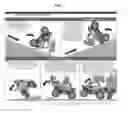
The US Government Accountability Office (GAO) estimated in a recent report that there are over 400,000 injuries and 800 deaths result from ATV accidents in the average year. In FIG. 1 from that report, the GAO illustrates how typical ATV fatalities and injuries occur. Four of five the scenarios they show are rolling the vehicle or being thrown from it all things, as stated above, the a high seat position contribute to.
A purpose of the Adjustable Seat and Support System is to give an ATV rider the option of lowering the seat of an ATV, therefore lowering the center of gravity, plus making him or her more one with the vehicle and less likely to roll or be ejected.
Additionally, the cost of automobiles continues to escalate each year and the price of fuel is unstable. Global weather change has everyone concerned about carbon footprint. The world economy is swelling and many millions of people would like to find affordable 4 wheel transportation for good and bad roads. A small on and off the road 4 wheel vehicle with a straddle seat and handlebars, that is safe from rollovers and driver ejection, is not known or common With the Adjustable Seat and Support System and some design changes to an ATV, a useful vehicle could be created that could:
-
- Have fuel economy easily over 50 miles per gallon
- Reduce the carbon footprint
- Be purchased for half the cost of an automobile
- Open the market for future luxury models, designed for current luxury motorcycle riders who would like 4 wheels and the feel of a motorcycle
- Help millions in developing countries and across the world get affordable 4 wheel transportation that will be safe and useable on all their roads
The current design of seats and supports shows little or no use of the architecture and geometry used in the Adjustable Seat and Support System. This invention can offer many advantages that will be shown to be useful in many different seat applications as well as many devices used to support, lift and move objects.
SUMMARY
A support adjustment system used to lift An object in parallelogram motion or non-parallelogram motion using a rail and two links.
BRIEF EXPLANATION OF DRAWINGS
FIG. 1 Typical ATV fatality and injury Scenarios from GOA Report
FIG. 2 A portion of a drawing from “Seat Suspension Method” shown in patent U.S. Pat. No. 6,354,556
FIG. 3 First Embodiment with the seat at the lowest position and parallelogram marked
FIG. 4 First Embodiment with the seat at the lowest position and parallelogram movement
FIG. 5 Elevated view of the Seat Assembly with seat at its lowest position.
FIG. 6 Close-up view of the Seat Assembly in a middle latched position to show the track, roller, latch pin and latch holes.
FIG. 7 Seat Assembly with the seat latched in the highest position.
FIG. 8 Seat Assembly with the seat latched in a middle height position.
FIG. 9 Seat Assembly mounted on an ATV
FIG. 10 Second Embodiment with a single slide rail
FIG. 11 Close up of Slide Pivot and Magnet Latch Assembly
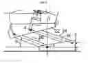
FIG. 12 Orthographic view of Second Embodiment with parallelogram lines
FIG. 13 Non-Parallelogram motion using a straight line instead of a circular arc
DETAILED DESCRIPTION
Seats are known to be adjustable in many ways. One way commonly known to move a seat horizontally and vertically simultaneously is to use geometry often referred to as a parallelogram. The parallelogram has two sets of opposite, parallel and equal sides. If the sides are of fixed length and the sides can pivot at their connecting points, and one of the 4 sides is fixed in place when one of the other sides is moved, all three of the unfixed sides move and stay parallel to their opposite sides. If the side opposite the fixed is a surface used to support a seat or other object, then when it moves it stays in parallel with the plane occupied by the fixed side. Typically this means there are 4 visible links in a parallelogram like seat suspension method shown in patent U.S. Pat. No. 6,354,556.
Some embodiments of the invention involve a new use of this old geometry, the parallelogram. The invention starts with 4 sided geometry and two sets of opposite, parallel and equal sides. One of the sides is fixed in place and all sides are of fixed length. The fixed side and one adjacent side are not typically visible. They are connected to and/or part of a circular arc that is visible. Said arc is fixed in place. The fixed side is a fixed invisible line from the center of curvature of said arc (which is the invisible fixed pivot point 8) to the lower pivot (which is the visible fixed pivot point 6) on a moveable upright link. The other hidden moveable line is a radius line that runs from the center of curvature of said arc, said invisible fixed pivot point 8, to the arc at a pivot and follow point 2′ at one end of the seat. A line, a support surface line, that runs from said pivot and follow point 2′ at one end of the seat to a pivot point four 4′, at the other end of the seat is the side that is equal in length and parallel to said fixed invisible line. A line from said pivot point four 4′ runs through said moveable upright link to said visible fixed pivot point 6 and is of equal length and parallel to said radius line. As said pivot and follow point 2′ is moved along said arc, said support surface line is moved simultaneously horizontally and vertically along said arc. Because of the parallelogram like movement stays in parallel to its original position and said fixed side.
In FIG. 4 the lines and pivot points are seen in the lower and upper positions on said arc. As can be seen in this fig, the seat will move in parallelogram like motion to the high position and stay parallel to its original position.
All lines mentioned above and below are straight unless specified otherwise, and equal length is to be interpreted as of substantially equal length. Parallel is to be interpreted as substantially parallel.
The following parts and features have substantially mirrored image parts or features on the right and left side of this sub-assembly: Rear Support Arm 40, Support lower pivot 42, Support upper pivot 44, Pan to follower bracket 48, Track Follower Roller 50, Seat track 52, Seat Track Side Frame 54, Latch Pin 56 and Latch Pin Holes 58.
The Seat Track Side Frame 54 is rigidly mounted to the ATV frame. Seat Track Side Frame 54 may be a section of the ATV frame. In this document “the ATV frame” will refer to the tubular or solid frame that substantially runs around the outside of the center portion of the ATV. The ATV frame runs from front to rear typically very near the lowest point of the ATV, then upward at some angle or curve to above the engine, over the top of the engine for some distance, and then down again to the bottom of the ATV. Some ATV frames do not completely go above the engine but have two frame portions at the left and right sides near the top of the engine. This is not intended to give an exhaustive description of all ATV frames but just a typical description to locate where Seat Track Side Frame 54 is part of or attached to an ATV frame and to locate parts and features mentioned later. The top of Seat Track Side Frame 54 is attached at a plane near to the top of ATV frame, typically above the transmission portion of the engine/transmission. Seat Track Side Frame 54 runs at an angle toward the rear and bottom of the ATV. The bottom of Seat Track Side Frame 54 is attached rigidly to the ATV frame near the bottom, System Mounting Frame 32 or Lower Seat Frame 60. Seat track 52 and Latch Pin Holes 58 are formed by any means effective or cut into Seat Track Side Frame 54. Latch Pin Holes 58 run in a pattern substantially down the center of Seat track 52.
Track Follower Roller 50 has a diameter that is slightly smaller than the width of Seat track 52. Track Follower Roller 50 is rotatably attached to Pan to follower bracket 48 in such a way as to force said roller to follow Seat track 52. Pan to follower bracket 48 is rigidly attached to a front portion of Support Pan 46. Rear Support Arm 40 is pivotally attached to a rear portion of Support Pan 46 at Support upper pivot 44. The other end of Rear Support Arm 40 is pivotally attached to Lower Seat Frame 60 or a lower portion of the ATV frame or a suitable attachment to System Mounting Frame 32 at Support lower pivot 42.
FIG. 8 is a view of the Seat Sub-Assembly with the seat latched in a middle height position. FIG. 7 is a view of the Seat Sub-Assembly with the seat latched in the highest position. FIG. 6 is a close-up view of a portion of Seat Sub-Assembly 4. Latch Pin 56 is mounted so it can slide in and out on the center line of Track Follower Roller 50. To latch, the seat height position Latch Pin 56 is forced or moved by a spring into a Latch Pin Hole 58. To unlatch, the seat height Latch Pin 56 is forced out of or moved out by a spring of Latch Pin Hole 58. Many means are known of pulling or pushing a pin in or out of a hole and are not shown here.
The Support Pan 46 can be moved up or down to any position on the seat track or latched in any of the position made available by Latch Pin Holes 58. There can be any number of Latch Pin Holes 58. Latch Pin Holes 58 may or may not go all the way thru Seat Track Side Frame 54.
FIG. 10 is a view of the Second Embodiment with a single slide rail. Shown is an embodiment of the Adjustable Seat and Support System with a single rail that is part of the frame of an ATV. The seat is at the top position on the rail.
FIG. 12 is an Orthographic view of the Second Embodiment with parallelogram lines showing the movement of the seat. A Slide Pivot and Magnetic Latch Assembly 62 moves slidably along Slide and Latch rail 64 and causes a Pivot point at the front of the seat 70 to follow the arc as shown. Said pivot point pivotably attaches the Seat 74 to said Slide Pivot and Magnetic Latch Assembly. Square latch pins are urged into the square apertures on said Slide and latch rail 64 to hold seat position. Electromagnetic Latch Pulls 66 shown in FIG. 11 pull the square pins from their apertures and allow the rider to adjust the seat position at the push of a button. Behind covers at visible fixed pivot point 6 there are springs that have just enough tension to cause the seat to rise to the highest position. For the rider to change the position of the seat, the selection button is pushed and held until desired position is reached.
FIG. 13 is a view of Non-Parallelogram motion using a straight line instead of a circular arc as a third embodiment of this invention. When a straight line is used, the movement of the seat deviates significantly from the movement of the parallelogram. When a straight line is used for the rail, the back of the seat pitches up significantly as the seat moves down, in this movement about 12 degrees. This can be useful on an ATV or any straddle seat vehicle that uses one set of foot pegs slightly forward of the driver. As the seat goes down, the legs of the rider tend to fold up under him, pushing him or her away from the handle bars. When the back of the seat pitches up, it tends to cause the rider to move forward, helping the driver compensate for the folded legs.
Thus the reader will see that at least, embodiment of the Adjustable Support and Seat System provides many advantages including but not limited to:
-
- Space, weight and material saved
- Simplified design
- Greater rigidity
- Easier to index positions
While the above description contains many specificities, they should not be construed as limitations of the scope, but rather, as an exemplification of one or several embodiments there of. Many many other variations are possible.
Accordingly, the scope should be determined not by the embodiments illustrated, but by the appended claims and their legal equivalents.
LIST OF REFERENCE NUMBERS USED IN DRAWINGS
-
- 2 Pivot And Follow Point
- 4 Pivot Point Four
- 6 Visible Fixed Pivot Point
- 8 Invisible Fixed Pivot Point
- 10 Fixed Invisible Line
- 14 Invisible Radius Line
- 16 Arc
- 40 Rear Support Arm
- 42 Support Lower Pivot
- 44 Support Upper Pivot
- 46 Support Pan
- 48 Pan To Follower Bracket
- 50 Track Follower Roller
- 52 Seat Track
- 54 Seat Track Frame
- 56 Latch Pin
- 58 Latch Pin Holes
- 60 Lower Seat Frame
- 62 Slide Pivot And Magnetic Latch Assembly
- 64 Slide And Latch Rail
- 66 Electromagnetic Latch Pulls
- 68 Slide And Pivot Block With Internal Rollers
- 70 Pivot Point At Front Of Seat
- 72 Square Latch Holes
- 74 Seat
- 76 Seat Position At Lowest Latch
- 78 Seat Front Pivot
- 80 Rear Support Link
- 82 Position Of Rear Support Link When Seat At Lowest Latch
- 84 Tires
- 86 Vehicle Frame
- 88 Fuel Tank
- 90 Handlebars
- 92 Muffler and Protection Bracket
- 94 Taillight grab bar
Claims
I claim:1. A support adjustment system comprising:
A Rail
Two link with pivotable connections at both ends connect to each other pivotably
A means to slidably connect one end of one link to a portion of the rail
Said rail is formed or contains a path for a means to slidably connect it to the rail and pivotably connect to one end of the link
Images & Drawings included:


Sources:
- United States Patent and Trademark Office - verify current appl. status at the USPTO↗
Similar patent applications:
- » 20070106188
Adjustable seating support system - » 20230347794
METHOD AND SEAT ADJUSTMENT SYSTEM FOR SUPPORTING RELAXATION OF AN OCCUPANT SITTING ON A VEHICLE SEAT OF A MOTOR VEHICLE - » 20140346822
Adjustable Seat And Support System - » 20060001304
Seat with adjustable support system - » 20060103204
Seat with adjustable support system - » 20050127735
Vehicle seat with adjustable support system - » 20250033534
ADJUSTABLE SUPPORT FOR A SEAT SYSTEM - » 20060061167
Adjustable seat cushion thigh support system and method - » 20110025111
SEATING SYSTEMS INCORPORATING SELF-INFLATING ADJUSTABLE SUPPORTS - » 20180055230
GRADUAL ADJUSTMENT SYSTEM AND METHOD OF LUMBAR SUPPORT OF SEAT
Recent applications in this class:
- » 20250026245 2025-01-23
ADJUSTABLE SEAT CUSHION INSERT - » 20240336166 2024-10-10
SEAT - » 20240253528 2024-08-01
Seat for vehicle - » 20240166106 2024-05-23
Vehicle seat - » 20240092227 2024-03-21
Seat bolster activator - » 20230191952 2023-06-22
Vehicle seat with blocking device for a lowerable seat part of the vehicle seat - » 20210009008 2021-01-14
Passenger-receiving device and related public transportation vehicle - » 20200384894 2020-12-10
Passenger transport seats with lateral seat lips - » 20200156503 2020-05-21
Side extension device for seat of vehicle - » 20200139849 2020-05-07
Vehicle seat