Tool changer equipped with covers
US20150087487A1
2015-03-26
14/484,331
2014-09-12
✅ Patent granted
US 9,656,362 B2
2017-05-23
-
-
Erica E Cadugan
Hauptman Ham, LLP
2034-12-31
Abstract:
A tool changer is equipped with a turret having plural grips for use to grip tools as well as with a front cover and rear cover adapted to cover a front face and rear face of the turret. Furthermore, a protrusion is installed on the rear cover in a neighborhood of a gap between the front cover and the rear cover, being configured to block intrusion of chips or cutting fluid into the gap between the front cover and the rear cover from a top face of the rear cover.
Assignee:
- FANUC CORPORATION 3,981 🇯🇵 Yamanashi, Japan
Applicant:
Interested in similar patents?
Get notified when new applications in this technology area are published.
Classification:
B23Q3/15773 » CPC further
Devices holding, supporting, or positioning work or tools, of a kind normally removable from the machine; Arrangements for automatic insertion or removal of tools, e.g. combined with manual handling of rotary tools a transfer device taking the tool from a storage device and passing it on to other transfer devices, which insert it in a spindle
B23Q3/157 IPC
Devices holding, supporting, or positioning work or tools, of a kind normally removable from the machine; Arrangements for automatic insertion or removal of tools, e.g. combined with manual handling of rotary tools
B23Q11/08 » CPC main
Accessories fitted to machine tools for keeping tools or parts of the machine in good working condition or for cooling work ; Safety devices specially combined with or arranged in, or specially adapted for use in connection with, machine tools Protective coverings for parts of machine tools; Splash guards
B23Q3/15534 » CPC further
Devices holding, supporting, or positioning work or tools, of a kind normally removable from the machine; Arrangements for automatic insertion or removal of tools, e.g. combined with manual handling parts of devices for automatically inserting or removing tools; Storage devices; Drive mechanisms therefor Magazines mounted on the spindle
B23Q3/15706 » CPC further
Devices holding, supporting, or positioning work or tools, of a kind normally removable from the machine; Arrangements for automatic insertion or removal of tools, e.g. combined with manual handling of rotary tools a single tool being inserted in a spindle directly from a storage device, i.e. without using transfer devices
Y10T483/115 » CPC further
Tool changing with safety means Guard
Y10T483/1795 » CPC further
Tool changing including machine tool or component; Rotary spindle machine tool [e.g., milling machine, boring, machine, grinding machine, etc.]; Direct tool exchange between spindle and matrix; Spindle comprises tool changer Matrix indexes selected tool to transfer position
B23Q3/155 IPC
Devices holding, supporting, or positioning work or tools, of a kind normally removable from the machine Arrangements for automatic insertion or removal of tools, e.g. combined with manual handling
Y10T483/1748 » CPC further
Tool changing including machine tool or component; Rotary spindle machine tool [e.g., milling machine, boring, machine, grinding machine, etc.] Tool changer between spindle and matrix
Description
BACKGROUND OF THE INVENTION
1. Field of the Invention
The present invention relates to a tool changer equipped with covers to prevent intrusion of foreign matter into a turret.
2. Description of the Related Art
A tool changer which automatically changes a tool mounted on a spindle of a machine tool are used conventionally. Plural tools necessary for operations are set in advance on the tool changer, which is configured to automatically change the tool mounted on the spindle of the machine tool to a specified tool according to machining conditions.
Examples of a machine tool equipped with such an automatic tool changer adapted to automatically change the tool includes a machine tool equipped with a turret which in turn is equipped with plural grips adapted to grip tools. Such a machine tool is disclosed in Japanese Patent Application Laid-Open No. 2010-99766. The machine tool has a turret in which plural tools are mounted and changes the tool mounted on the spindle by indexing the turret, making it possible to change the tool precisely at high speed. However, the turret and the turret base are simply connected with each other with a space provided between the front side of the turret and the base, and consequently, there is fear that chips produced during machining or a cutting fluid might intrude inside the turret.
FIG. 3 shows an automatic tool changer 2 adapted to automatically change a tool 4 mounted on a spindle 3 of a machine tool 1, according to conventional art.
In the automatic tool changer 2, as shown in FIG. 3, the turret 6 is equipped with covers to prevent intrusion of chips and cutting fluid into the turret 6 when a workpiece is machined. The machine tool 1 includes a spindle 3 and a spindle motor 5 adapted to drive the spindle 3 and a tool 4 is mounted on a tip of the spindle 3. Also, the spindle 3 is connected with a Z-axis motor 11 via a Z-axis ball screw 10, and the spindle 3 can be driven upward and downward by the Z-axis motor 11. Furthermore, the turret 6 is provided as a member for use to change the tool 4.
The turret 6 is equipped with a front cover 61 and rear cover 62 to avoid impacts on structural members (not shown) inside the turret 6, where the front cover 61 plays a role in preventing intrusion of chips and cutting fluid through the front face of the turret 6 while the rear cover 62 plays a role in preventing intrusion of chips and cutting fluid through the rear face of the turret 6.
Thus, depending on the geometry of the rear cover 62, chips and cutting fluid may tend to gather on a top side (part A) of a cylindrical portion 64. Then, in changing the tool 4, the spindle 3 is driven upward and downward by the Z-axis motor 11. Here, as the spindle 3 is provided with a cam 7, when the spindle 3 is moved up and down, the turret 6 is caused to perform oscillating motion by a cam follower 8 configured to follow the cam 7. Consequently, there is fear that during the oscillating motion, the chips and cutting fluid gathered on the top side (part A) of the cylindrical portion 64 might intrude inside the turret 6 through a gap 65 between the front cover 61 and rear cover 62 as indicated by a path B and adversely affect the structural members inside the turret 6.
SUMMARY OF THE INVENTION
Thus, an object of the present invention is to provide a tool changer equipped with covers adapted to prevent intrusion of chips and cutting fluid into a turret.
A tool changer according to the present invention is equipped with a turret having plural grips for use to grip tools and adapted to change a tool by indexing a desired tool by rotating the turret. The tool changer further comprises: a front cover adapted to cover a front face of the turret; a rear cover adapted to cover a rear face of the turret; and a protrusion provided on the rear cover in a neighborhood of a gap between the front cover and the rear cover. The protrusion is configured to block a path for chips or cutting fluid to intrude into the gap between the front cover and the rear cover from a top face of the front cover or a top face of the rear cover.
The present invention provides a tool changer equipped with covers capable of preventing chips produced during machining of a workpiece and cutting fluid used for machining from intruding inside the turret through the gap between the front cover and the rear cover.
BRIEF DESCRIPTION OF THE DRAWINGS
The above and other objects and features of the present invention will become apparent from the following description of the embodiments taken in conjunction with the accompanying drawings, wherein:
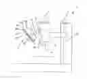
FIG. 1 is a schematic side view of a first embodiment of a tool changer equipped with covers according to the present invention;
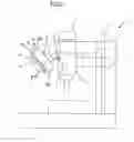
FIG. 2 is a schematic side view of a second embodiment of a tool changer equipped with covers according to the present invention; and
FIG. 3 is a schematic side view of a tool changer equipped with covers according to conventional art.
DETAILED DESCRIPTION OF THE PREFERRED EMBODIMENTS
First, a first embodiment of a tool changer equipped with covers according to the present invention will be described with reference to FIG. 1.
The present embodiment differs from a conventional art shown in FIG. 3 in that a protrusion 66 is provided on the rear cover 62 at an upper half portion thereof so as to face the front cover 61. As the protrusion 66 is provided on the rear cover 62, a V groove 68 is formed between a cylindrical portion 64 of the rear cover 62 and the protrusion 66. With this V groove 68, chips produced during machining of a workpiece and cutting fluid used for machining can be prevented from intruding inside the turret 6 through the gap 65 formed between the front cover 61 and rear cover 62.
Also, to change the tool 4, the spindle 3 is driven by the Z-axis motor 11 so as to move up and down. In so doing, since the spindle 3 is provided with a cam 7, when the spindle 3 is moved up and down, the turret 6 is oscillated by a cam follower 8 configured to follow the cam 7. The oscillating motion shakes any chips built up on a top side of the cylindrical portion 64 of the rear cover 62 out of the turret 6 along the V groove 68. Also, any cutting fluid gathered on the top side of the cylindrical portion 64 of the rear cover 62 is shaken out of the turret 6 along the V groove 68 without intruding inside the turret 6. This prevents chips and cutting fluid from intruding inside the turret 6 and thereby prevents impacts on structural members (not shown) inside the turret 6.
Although, in the present embodiment, the protrusion 66 is provided on the rear cover 62 at an upper half thereof so as to face the front cover 61, the protrusion 66 may be provided on the rear cover 62 around the entire circumference thereof. Further, the protrusion 66 may be provided on the front cover 61, instead of the rear cover 62, on that side of the front cover 61 which faces the rear cover 62, or the protrusion 66 may be provided separately from the front cover 61 and rear cover 62.
Next, a second embodiment of a tool changer equipped with covers according to the present invention will be described with reference to FIG. 2.
Whereas in the first embodiment described above, the protrusion 66 projects almost perpendicularly to the cylindrical portion 64 of the rear cover 62 as shown in FIG. 1, the second embodiment differs from the first embodiment in that the protrusion 66 projects at an angle of 90 degrees or more with respect to the cylindrical portion 64 of the rear cover 62 (that is, forming an oblique protrusion 67).
According to the present embodiment, the oblique protrusion 67 is provided on the rear cover 62 around the entire circumference thereof on the side which faces the front cover 61. As the oblique protrusion 66 is provided on the rear cover 62, a V groove 68 is formed between a cylindrical portion 64 of the rear cover 62 and the oblique protrusion 66. With this V groove 68, chips produced during machining of a workpiece and cutting fluid used for machining can be prevented from intruding inside the turret 6 through the gap 65 formed between the front cover 61 and rear cover 62.
Also, to change the tool 4, the spindle 3 is driven by the Z-axis motor 11 so as to move up and down. In so doing, since the spindle 3 is provided with a cam 7, when the spindle 3 is moved up and down, the turret 6 is oscillated by a cam follower 8 configured to follow the cam 7. The oscillating motion shakes any chips built up on a top side of the cylindrical portion 64 of the rear cover 62 out of the turret 6 along the V groove 68. Also, any cutting fluid gathered on the top side of the cylindrical portion 64 of the rear cover 62 is shaken out of the turret 6 along the V groove 68 without intruding inside the turret 6. This prevents chips and cutting fluid from intruding inside the turret 6 and thereby prevents impacts on structural members (not shown) inside the turret 6.
Although in the present embodiment, the oblique protrusion 67 is provided on the rear cover 62 around the entire circumference thereof, the oblique protrusion 67 may be provided on the rear cover 62 at only an upper half portion thereof. Further, the oblique protrusion 67 may be provided on the front cover 61, instead of the rear cover 62, on that side of the front cover 61 which faces the rear cover 62, or the protrusion, or the oblique protrusion 67 may be provided separately from the front cover 61 and rear cover 62.
Claims
What is claimed is:1. A tool changer equipped with a turret having plural grips for use to grip tools and adapted to change a tool by indexing a desired tool by rotating the turret, the tool changer further comprising:
a front cover adapted to cover a front face of the turret;
a rear cover adapted to cover a rear face of the turret; and
a protrusion provided on the rear cover in a neighborhood of a gap between the front cover and the rear cover, wherein
the protrusion is configured to block a path for chips or cutting fluid to intrude into the gap between the front cover and the rear cover from a top face of the front cover or a top face of the rear cover.
Images & Drawings included:

Sources:
- United States Patent and Trademark Office - verify current appl. status at the USPTO↗
Recent applications in this class:
- » 20250187128 2025-06-12
Apparatus for Catching Debris and Deflecting Coolant Splash for Use with Computer Numerical Controlled Machines - » 20240342847 2024-10-17
MACHINE TOOL AND PROTECTIVE MEMBER - » 20240157495 2024-05-16
Machine tool cable protection device - » 20240066649 2024-02-29
DOOR DEVICE OF MACHINE TOOL AND MACHINE TOOL - » 20230158622 2023-05-25
PROCESSING MACHINE - » 20230066355 2023-03-02
Self-locking linear guide rail channel detection device - » 20220184762 2022-06-16
Blade guard for saw of saw house and method - » 20220118572 2022-04-21
TILE SAW SPLASH GUARD AND RESERVOIR SYSTEM - » 20220105599 2022-04-07
Machine tool - » 20220097191 2022-03-31
MACHINE TOOL
Recent applications for this Assignee:
- » 20250258475 2025-08-14
COMPUTATION DEVICE, MACHINE TOOL, MACHINE TOOL CONTROL DEVICE, AND STORAGE MEDIUM - » 20250256398 2025-08-14
ROBOT CONTROL DEVICE, NUMERICAL CONTROL SYSTEM, AND NUMERICAL CONTROL METHOD - » 20250251710 2025-08-07
MOTOR MONITORING DEVICE - » 20250250525 2025-08-07
CELL CULTURE VESSEL AND CELL CULTURE DEVICE - » 20250249608 2025-08-07
WIRE-BODY-MANAGING DEVICE, WIRE-BODY-MANAGING METHOD, AND ROBOT - » 20250229441 2025-07-17
COVERING MEMBER FIXING STRUCTURE, MACHINE, AND ROBOT - » 20250224272 2025-07-10
LASER PATH DISPLAY DEVICE AND STORAGE MEDIUM - » 20250214228 2025-07-03
COUPLING STRUCTURE AND PARALLEL LINK ROBOT - » 20250209646 2025-06-26
INDUSTRIAL SYSTEM CONTROL DEVICE, INDUSTRIAL SYSTEM, AND IMAGE ACQUISITION METHOD - » 20250208601 2025-06-26
INFORMATION PROCESSING DEVICE, MACHINE TOOL CONTROL DEVICE, AND NON-TRANSITORY COMPUTER-READABLE MEDIUM STORING A COMPUTER PROGRAM