LIFTING SUPPORT FRAME
US20150102276A1
2015-04-16
14/052,853
2013-10-14
Abstract:
This invention discloses a lifting support frame, comprising a frame, a fixed seat, a hydraulic cylinder, a guide spindle, a guide plate and a support plate. In the frame the fixed seat is fixedly connected, at both sides of the fixed seat, a hydraulic cylinder is connected, and in the middle of the fixed plate, the guide spindle is connected fixedly. Above the said hydraulic cylinder and guide spindle, a horizontal guide plate is fixedly connected, where a support plate is provided. This invention solves the problem existing in the techniques, and is featured with high efficiency and low cost.
Assignee:
- NANTONG JINYUE GARMENT DESIGN CO., LTD. 1 🇨🇳 Nantong, China
Interested in similar patents?
Get notified when new applications in this technology area are published.
Classification:
B66F3/24 » CPC main
Devices, e.g. jacks, adapted for uninterrupted lifting of loads fluid-pressure operated
B66F3/25 » CPC further
Devices, e.g. jacks, adapted for uninterrupted lifting of loads fluid-pressure operated Constructional features
Description
TECHNICAL FIELD
This invention is relating to a lifting structure, specifically to a lifting support frame.
BACKGROUND OF TECHNOLOGY
In the working process of production lines in the existing light industry, manufacturing industry and textile industry, the material and semi-products are needed to be moved or shifted to other places as required. Normally manual handling or simple lifting structure is applied for the handling. The manual handling is a labor-consumable and material-consumable process with low efficiency, while the simple lifting structure used in the process is less stable, impacting the work efficiency.
CONTENT OF THE INVENTION
The purpose of the invention: in order to achieve the above purpose, this invention provides a high efficiency, low cost lifting support frame.
The technical solution: in order to achieve the above purpose, this invention adopts the following technical solution:
A lifting support frame consists of the frame, fixed seat, hydraulic cylinder, guide spindle, guide plate and support plate. In the frame the fixed seat is firmly connected, at both sides of the fixed seat, a hydraulic cylinder is connected, and in the middle of the fixed seat, the guide spindle is connected fixedly. Above the said hydraulic cylinder and guide spindle, a horizontal guide plate is fixedly connected, where a support plate is provided on the guide plate.
A guide slider for the clearance fit to the guide spindle.
The upper part of the hydraulic cylinder and guide spindle are fixedly connected to the guide plate through hexagonal bolts.
The hydraulic cylinder stroke is controlled by the solenoid switch.
The frame is made up of the square tubes by welding.
The anti-sliding convex point is set on the support plate surface.
Beneficial effect: the lifting support frame during the production line process solves the problem that a workpiece requires rapid rising up and coming down when necessary. In addition, it provides high efficiency and low cost, as well as the simple operation, energy-saving and environmental protection, appropriate for the wide range of application in the industry.
NOTES TO THE FIGURE
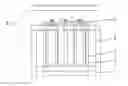
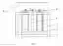
FIG. 1 is the sketch for the structure of the invention.
THE SPECIFIC IMPLEMENTATION
Specification
FIG. 1 shows a lifting support frame, including frame 1, fixed seat 2, hydraulic cylinder 3, guide spindle 4, guide plate 5 and support plate 6. In the frame 1, a fixed seat 2 is connected, at both sides of the fixed seat 2, a hydraulic cylinder 3 is connected respectively, in the middle of the fixed seat 2, a guide spindle 4 is firmly connected, above the hydraulic cylinder 3 and guide spindle 4, firmly connected is the horizontal guide plate 5, where a support plate 6 is connected.
A guide slider for clearance fit to the guide spindle 4 is provided, and the upper part of the hydraulic cylinder 3 and guide spindle 4 are fixedly connected to the guide plate 5 through hexagonal bolts. The stroke of the hydraulic cylinder 3 is controlled by the solenoid switch. The frame 1 is made up of the square tubes by welding. The anti-sliding convex point is set on the surface of the support plate 6.
Claims
1. A lifting support frame is characterized as: it includes the frame, fixed seat, hydraulic cylinder, guide spindle, guide plate and support plate. In the frame the fixed seat is firmly connected, at both sides of the fixed seat, a hydraulic cylinder is connected, and in the middle of the fixed seat, the guide spindle is connected fixedly. Above the said hydraulic cylinder and guide spindle, a horizontal guide plate is fixedly connected, where a support plate is provided on the guide plate.
2. According to the patent claim 1, the lifting support frame is featured with a guide slider for the clearance fit to the guide spindle.
3. According to the patent claim 1, the lifting support frame is featured with upper part of hydraulic cylinder and guide spindle is fixedly connected to the guide plate through hexagonal bolts.
4. According to the patent claim 1, the lifting support frame is featured with the hydraulic cylinder stroke controlled by the solenoid switch.
5. According to the patent claim 1, the lifting support frame is featured with the square tubes welded to form the frame.
6. According to the patent claim 1, the lifting support frame is featured with the anti-sliding convex point on the support plate surface.
Images & Drawings included:
Sources:
- United States Patent and Trademark Office - verify current appl. status at the USPTO↗
Similar patent applications:
- » 20050217025
Standing frame with lift, support and transport of user - » 20150000942
Farm implement having a frame supported by a lift wheel assembly - » 20120217101
Hosting machine supporting frame for jump lifts of elevators - » 20150021057
Farm Implement Having A Frame Supported By A Lift Wheel Assembly And A Pair Of Gull Wings - » 20150025758
Farm implement having a frame supported by a lift wheel assembly and a pair of gull wings - » 20070065236
Mining roof support frame with base skids lifting device - » 20200406806
Cargo Container and Lift Frame Assemblies with Movable Support Legs - » 20120011650
Support frame assembly for patient lifts - » 20240425333
LIFTING GEAR HAVING A LIFTING FRAME MOVABLE IN A MOVEMENT DIRECTION RELATIVE TO A SUPPORTING PART OF THE LIFTING GEAR, AND METHOD FOR OPERATING A LIFTING GEAR - » 20120280190
Base frame for a lifting apparatus having removable support members
Recent applications in this class:
- » 20210238018 2021-08-05
HYDRAULIC SYNCHRONIZER - » 20190023543 2019-01-24
Hydraulic synchronizer - » 20180179035 2018-06-28
Lifting System for Lifting a Vehicle with Indirect Height Measurement and Method Therefor - » 20180141791 2018-05-24
Hydraulic Jack System - » 20180118537 2018-05-03
Airplane jack apparatus - » 20180118536 2018-05-03
Apparatus and method to move a pressure vessel between horizontal and vertical positions - » 20170369290 2017-12-28
Self-contained Automatic Jack - » 20170327357 2017-11-16
Jack with two masts - » 20170260031 2017-09-14
Self-inflating Buoyancy Driven Elevator - » 20160272470 2016-09-22
Apparatus and method for controlling jacks