Coupling of a turbopump for molten salts
US20150107245A1
2015-04-23
14/403,844
2013-05-23
✅ Patent granted
US 9,803,625 B2
2017-10-31
WO; PCT/EP2013/060577; 20130523
WO; WO2013/174901; 20131128
Mark Laurenzi | Xiaoting Hu
Reinhart Boerner Van Deuren P.C.
2033-10-02
Abstract:
The invention relates to a device comprising at least one vertical pump (3) and at least one associated turbine (4) for transporting, over a level difference, a heat-transfer fluid brought to a high temperature, wherein the device further comprises a device for mechanically coupling the turbine (4) with the pump (3), comprising a gearbox (21) with a gimbal coupling (41) located on the turbine (4) side, allowing the mechanical energy produced by the turbine (4) to be reused to actuate the pump (3).
Assignee:
- COCKERILL MAINTENANCE & INGENIERIE S.A. 24 🇧🇪 Seraing, Belgium
Applicant:
Interested in similar patents?
Get notified when new applications in this technology area are published.
Classification:
F03G6/067 » CPC main
Devices for producing mechanical power from solar energy with solar energy concentrating means having a Rankine cycle Binary cycle plants where the fluid from the solar collector heats the working fluid via a heat exchanger
F04D25/02 IPC
Pumping installations or systems Units comprising pumps and their driving means
F04D25/024 » CPC further
Pumping installations or systems; Units comprising pumps and their driving means the driving means being assisted by a power recovery turbine
F05D2210/10 » CPC further
Working fluids Kind or type
F05D2220/31 » CPC further
Application in turbines in steam turbines
F05D2260/20 » CPC further
Function Heat transfer, e.g. cooling
F03G6/06 IPC
Devices for producing mechanical power from solar energy with solar energy concentrating means
F01D13/02 » CPC further
Combinations of two or more machines or engines Working-fluid interconnection of machines or engines
F01D15/08 » CPC further
Adaptations of machines or engines for special use; Combinations of engines with devices driven thereby Adaptations for driving, or combinations with, pumps
F03B13/00 » CPC further
Adaptations of machines or engines for special use; Combinations of machines or engines with driving or driven apparatus ; Power stations or aggregates
F04D13/021 » CPC further
Pumping installations or systems; Units comprising pumps and their driving means containing a coupling
F01D15/12 » CPC further
Adaptations of machines or engines for special use; Combinations of engines with devices driven thereby Combinations with mechanical gearing
F22B1/006 » CPC further
Methods of steam generation characterised by form of heating method using solar heat
F22B1/00 IPC
Methods of steam generation characterised by form of heating method
F22B1/00 IPC
General aspects of, or methods for, steam generation
F04D13/04 » CPC further
Pumping installations or systems; Units comprising pumps and their driving means the pump being fluid driven
F04D7/06 » CPC further
Pumps adapted for handling specific fluids, e.g. by selection of specific materials for pumps or pump parts of centrifugal type the fluids being hot or corrosive, e.g. liquid metals
F01K3/12 » CPC further
Plants characterised by the use of steam or heat accumulators, or intermediate steam heaters, therein having two or more accumulators
F03B13/06 » CPC further
Adaptations of machines or engines for special use; Combinations of machines or engines with driving or driven apparatus ; Power stations or aggregates Stations or aggregates of water-storage type, e.g. comprising a turbine and a pump
F28D2020/0047 » CPC further
Heat storage plants or apparatus in general; Regenerative heat-exchange apparatus not covered by groups or using liquid heat storage material using molten salts or liquid metals
Y02E10/46 » CPC further
Energy generation through renewable energy sources; Solar thermal energy, e.g. solar towers Conversion of thermal power into mechanical power, e.g. Rankine, Stirling or solar thermal engines
Y02E10/46 » CPC further
Energy generation through renewable energy sources; Solar thermal energy, e.g. solar towers Conversion of thermal power into mechanical power, e.g. Rankine, Stirling or solar thermal engines
F04D7/02 » CPC further
Pumps adapted for handling specific fluids, e.g. by selection of specific materials for pumps or pump parts of centrifugal type
F03G6/00 IPC
Devices for producing mechanical power from solar energy
F28D20/00 IPC
Heat storage plants or apparatus in general; Regenerative heat-exchange apparatus not covered by groups or
F01D15/10 » CPC further
Adaptations of machines or engines for special use; Combinations of engines with devices driven thereby Adaptations for driving, or combinations with, electric generators
F01K7/22 » CPC further
Steam engine plants characterised by the use of specific types of engine ; Plants or engines characterised by their use of special steam systems, cycles or processes ; Control means specially adapted for such systems, cycles or processes; Use of withdrawn or exhaust steam for feed-water heating the engines being only of turbine type the turbines having inter-stage steam heating
F04D13/02 » CPC further
Pumping installations or systems Units comprising pumps and their driving means
Description
FIELD OF THE INVENTION
The present invention relates to the field of thermal solar power plants. In particular, the subject-matter of the present application relates to concentrated solar power plants (CSP) of the type having tower solar receivers, using molten salts as heat-transfer fluid and in which vertical pumps are used for the circulation and transfer of the molten salts brought to a high temperature.
BACKGROUND OF THE INVENTION
In CSPs of the type having a central tower, a large number of heliostats (in the form of planar mirrors) reflect the solar light toward one or more solar receivers, situated at the apex of the tower, the heliostats being positioned such that the shadows created by the mirrors do not interfere with the adjacent mirrors.
The solar receiver, heated by the concentrated incident solar rays, will generate a hot fluid that will be next used at ground level to produce high-pressure steam capable of driving a turbine and of producing electricity.
The fluid heated at the apex of the tower can directly be steam, or air, or a thermal oil. However, it may also be a molten salt consisting of a mixture of two or three, or even more, specific salts used as thermal-transfer fluid.
For example, a mixture of sodium nitrate (NaNO3) and potassium nitrate (KNO3) is often used, for example at a 60%/40% ratio, forming an atmospheric-pressure eutectic with a melting temperature reduced to 220° C. and offering good chemical and thermal stability between the melting temperature and 600° C. By using a ternary mixture of salts, comprising lithium nitrate (LiNO3) in addition to the two aforementioned salts, it is even possible to obtain a eutectic having a melting temperature as low as 120° C.
One major advantage of this mixture of salts is the possibility to store it in large quantities at high temperature and atmospheric pressure, at a reduced cost. The storage allows to separate the capture of solar energy and the production of electricity, independently from sunshine and solar hour, including at night.
The operating principle of a combined-cycle CSP power plant is known and for example described in document WO 2011/077248.
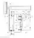
FIG. 1 diagrammatically shows the principle of a concentrated solar power plant of the tower type 1. The salt is maintained liquid in a first, insulated cold storage reservoir 2, at a temperature that is not lower than 260° C. Pumps 3 are necessary to bring the molten salt to the apex of the tower 1, and given the high flow rates required and the high density of the salt, the power absorbed by the pumps is relatively high, of an amplitude of 4 MW for a high-power power plant (typically 150 MW). At the apex of the tower, the salt is heated to 550° C. by the concentrated solar heat as specified above by means of one or more exchangers 20, distributed for example in four cavities, made up of thin-walled steel tubes. From there, the heated salt is returned to a second, insulated hot storage reservoir 5. The capacity of this reservoir depends on the supply duration required for the turbine that produces the electricity. When the production of electricity by the power plant is required, the hot salt is sent by a pump 6 to a conventional steam-generation system 7 to produce overheated steam for an electricity generator 9 having a turbine 8. FIG. 1 further shows a detailed example that is non-limiting with respect to the present invention, of a steam generator 7 according to the state of the art.
The molten salt circuit is referenced 17 and the water/steam circuit is referenced 18 in FIG. 1. Standard performance levels for a 150 MW installation are provided in Table 1.
It is also known that hydraulic power recovery turbines 4 (HRPT) could be used in this type of installation. These may be installed in the line for returning the heated salt to the storage reservoir, in order to recover the mechanical (gravitational) energy from the salt descending from the apex of the tower to the ground, the recoverable power having a typical amplitude of 3 MW for the aforementioned power plant.
In addition to a certain number of advantages, such as large storage capacity for energy at atmospheric pressure, low cost of the salt compatible with environmental safety, complete lack of fire risk, great simplicity and reduced costs for the solar receiver and associated equipment at the apex of the tower, CSP power plants with towers have several drawbacks, including the need to use very specific pumps, the design of molten salt/water-steam exchangers and the need to monitor the relatively high temperatures of the molten salts.
Document WO 2011/018814 discloses a method for locally pressurizing a first circuit in which a first heated fluid at a first pressure flows, and for providing that first fluid to a heat exchanger in order to exchange heat with a second fluid flowing in a second circuit at a second pressure that is greater than the first pressure. A pressurizing means, such as a pump, is provided in the first circuit to increase the pressure of the first fluid upstream from the inlet of the exchanger to a pressure corresponding to that of the second fluid. On the return line of the first circuit, a pressure-reducing means is provided, such as a butterfly valve, to decrease the pressure of the first fluid downstream from the outlet of the exchanger. A hydraulic motor comprising a turbine or a centrifuge pump used as a turbine is inserted downstream from the butterfly valve. The hydraulic motor and the pressurizing pump are connected to a same variable-speed electric motor working on the same shaft. Thus, the hydraulic motor actuated by the stream of pressurized fluid returning from the heat exchanger not only lowers the pressure of the fluid itself, but further provides the power necessary to operate the pressurizing pump, which consequently reduces the external electricity contribution.
AIMS OF THE INVENTION
The present invention aims to overcome the drawbacks of the state of the art.
In particular, the invention aims to reduce the absorption of power of the pumps for conveying the heat-transfer fluid to the apex of the central tower or offset it by recovering power in another location.
MAIN CHARACTERISTICS OF THE INVENTION
A first aim of the invention relates to a device comprising at least one vertical pump and at least one associated turbine for transporting, over a level difference, a heat-transfer fluid brought to a high temperature, the pump ensuring an upward movement of said fluid in a first section of a pipe from a first so-called cold reservoir and the turbine being actuated by said fluid during the downward return movement of said fluid in a second section of the pipe toward a second so-called hot reservoir, wherein the device further comprises a device for mechanically coupling the turbine with the pump, said mechanical coupling device comprising a gearbox with a gimbal coupling located on the turbine side, allowing the mechanical energy produced by the turbine to be reused to actuate the pump.
According to preferred embodiments of the invention, the device further comprises one or a suitable combination of the following features:
-
- the turbine is of the same type as the pump, but is used in the opposite direction;
- the pump or the turbine is of the type having a vertical axis, and is mono- or multi-staged, (multi)cellular with wheels having closed or semi-open radial vanes;
- the pump or the turbine is situated above the reservoir or has an immersed body;
- the pump and the turbine are designed to operate with a mixture of molten salts selected from the group consisting of sodium nitrate, potassium nitrate and lithium nitrate;
- the pump and the turbine are designed to operate with a mixture of molten salts, the pressures of which may reach up to 60 bar;
- the pump and the turbine are designed to operate with a mixture of molten salts whereof the temperature is comprised between 100 and 600° C.
A second aim of the present invention relates to a concentrated solar power plant comprising:
-
- a plurality of heliostats positioned on the ground around a central concentration tower, said tower comprising at its apex at least one thermo-solar exchanger;
- a first circuit for transporting molten salts from a first so-called cold storage reservoir to said exchanger and returning the molten salts brought to high temperature to a second so-called hot storage reservoir, said exchanger being located at the apex of the tower, i.e. at a height greater than that of the reservoirs;
- a second circuit for generating steam by means of a thermal exchange with the first circuit of molten salts and for producing electricity by means of a turbine/generator system;
wherein the power plant further comprises the device comprising at least one vertical pump and at least one associated turbine as described above.
Advantageously, the level difference between the molten-salt storage reservoirs and the exchangers at the apex of the tower is at least 150 m.
SHORT DESCRIPTION OF THE DRAWINGS
Embodiments according to the state of the art and to the invention are described below with more detail using the appended figures.
FIG. 1, already mentioned, diagrammatically shows a concentrated solar power plant CSP of the type having a central tower, with molten-salt circulation and coupling to a conventional electricity-production system.
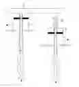
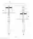
FIG. 2 shows a diagrammatic view of the mechanical coupling system according to the invention, between the pump for conveying the heat-transfer fluid to the central tower and the power-recovery turbine upon the return of the heat-transfer fluid to the storage reservoir.
DESCRIPTION OF PREFERRED EMBODIMENTS OF THE INVENTION
According to one preferred embodiment of the present invention, the pumps 3 and the power-recovery turbines 4 are mechanically coupled to each other in order to recover energy with the best possible yield.
A specific type of pump is necessary for the molten-salt application according to the invention. Such pumps will for example have the following features:
-
- vertical shaft;
- (multi)cellular, mono- or multi-staged construction with closed (or semi-open) wheels;
- installation above the salt reservoir, preferably with an immersed body, in order to simplify drainage;
- construction with a cantilevered shaft possible if the immersion depth of the pump, i.e., the distance between the bedplate and the suction tubing, is small enough; failing this, intermediate bearings necessary on the shaft line;
- shaft tightness with the bearing plate achieved by a labyrinth seal, with gravitational return of the leaks toward the reservoir;
- variable-frequency electric motor;
- use of appropriate materials and construction to withstand the high temperatures of the molten salts, etc. The materials used will for example withstand corrosion and abrasion.
Such pumps have already been used in the field of ground, parabolic solar collectors, but with relatively low fluid pressures.
The sizing of the pump must take into account the following three parameters: its length (for example, approximately 15 m), its variable speed and the high power required.
Advantageously, according to the invention, the power-recovery turbines will have the same design, optionally with specific vane wheels. In principle, operating the centrifugal pumps in the opposite direction suffices to achieve turbine mode. The pump-turbine mechanical coupling is ensured by a gearbox 21, with a gimbal coupler 41 on the turbine side in order to allow the differential expansions between the pump 3 and the turbine 4.
In the state of the art, only in-line coupling systems between horizontal pump and turbine, with clutch, are known.
Of course, the turbines 4 cannot recover the whole power consumed by the pumps, given the yields of the pumps and turbines, working in opposite directions.
Still according to the invention, the power difference will be compensated for by electric pumps of the same type (not shown), that are necessary to overcome pressure losses and to start the system anyway.
KEY
- 1 solar concentration tower
- 2 cold salt reservoir
- 3 supply pump to the tower
- 4 recovery turbine
- 5 hot salt reservoir
- 6 flow pump toward the steam generator
- 7 steam generator
- 8 turbine(s)
- 9 electricity generator
- 10 condenser
- 11 deaerator
- 12 economizer
- 13 kettle boiler
- 14 superheater
- 15 repeater
- 16 mixing pump
- 17 molten-salt circuit
- 18 water/steam circuit
- 20 solar receivers and exchangers
- 21 gear box
- 41 cardan shaft
| TABLE 1 | |
| TURBINE | |
| CYCLE |
| TOWER | Rated | ||||
| Duration | hours | 6 | 24 | 17.9 | |
| Storage | Therm MWh | 2553 | Elec MWh | 894 | 894 |
| Absorbed power | MW | 425 | Turbine | 37.3 | 50 |
| Salt flow rate | kg/s | 970 | To the exchangers | 242 | 325 |
| Temp. of the cold reservoir | ° C. | 260 | Condenser T | ° C. | 45.8 |
| Hot reservoir temperature | ° C. | 550 | Condenser P | bar | 0.10 |
| Salt weight | tons | 20952 | Deaerator T | ° C. | 105 |
| Volume | m3 | 12040 | |||
| Diameter | m | 31 | |||
| Height | m | 16 | |||
| Steam flow rate | kg/s | 30.8 | 41.2 | ||
| Steam pressure | bar | 120 | 120 | ||
| Steam temperature | ° C. | 530 | 530 | ||
| Reheating pressure | bar | 20 | 20 | ||
| Reheating temperature | ° C. | 530 | 530 | ||
Claims
1. A device comprising at least one vertical pump (3) and at least one associated turbine (4) for transporting, over a level difference, a heat-transfer fluid brought to a high temperature, the pump (3) ensuring an upward movement of said fluid in a first section of a pipe (17) from a first so-called cold reservoir (2) and the turbine (4) being actuated by said fluid during the downward return movement of said fluid in a second section of the pipe (17) toward a second so-called hot reservoir (5), wherein the device further comprises a mechanical device for coupling the turbine (4) with the pump (3), said mechanical coupling device comprising a gearbox (21) with a gimbal coupling (41) located on the turbine (4) side, allowing the mechanical energy produced by the turbine (4) to be reused to actuate the pump (3).
2. The device according to claim 1, wherein the turbine (4) is of the same type as the pump (3), but is used in the opposite direction.
3. The device according to claim 2, wherein the pump (3) or the turbine (4) is of the type with a vertical axis, and is mono- or multi-staged, (multi)cellular and has wheels with closed or semi-open radial vanes.
4. The device according to claim 3, wherein the pump (3) or the turbine (4) is situated above the reservoir or has an immersed body.
5. The device according to claim 1, wherein the pump (3) and the turbine (4) are designed to operate with a mixture of molten salts selected from the group consisting of sodium nitrate, potassium nitrate and lithium nitrate.
6. The device according to claim 1, wherein the pump (3) and the turbine (4) are designed to operate with a mixture of molten salts, the pressures of which may reach up to 60 bar.
7. The device according to claim 1, wherein the pump (3) and the turbine (4) are designed to operate with a mixture of molten salts whereof the temperature is comprised between 100 and 600° C.
8. A concentrated solar power plant comprising:
a plurality of heliostats positioned on the ground around a central concentration tower (1), said tower comprising at its apex at least one thermo-solar exchanger (20);
a first circuit (17) for transporting molten salts from a first so-called cold storage reservoir (2) to said exchanger (20) and returning the molten salts brought to high temperature to a second so-called hot storage reservoir (5), said exchanger (20) being located at the apex of the tower (1), i.e. at a height that is greater than that of the reservoirs (2, 5);
a second circuit (18) for generating steam by means of heat exchange with the first circuit (17) of molten salts and producing electricity by means of a turbine/generator system (7, 8, 9);
wherein the power plant further comprises the device comprising at least one vertical pump (3) and at least one associated turbine (4) according to claim 1.
Images & Drawings included:
Sources:
- United States Patent and Trademark Office - verify current appl. status at the USPTO↗
Recent applications in this class:
- » 20230313784 2023-10-05
Use of concentrated solar to enhance the power generation of the turboexpander in gas wells - » 20220099071 2022-03-31
Solar-aided coal-fired flexible power generation system and operation method thereof - » 20200232447 2020-07-23
SYSTEMS AND METHODS OF GENERATING SOLAR ENERGY AND DRY COOLING - » 20190048859 2019-02-14
SOLAR ENERGY POWER GENERATION SYSTEM - » 20180066635 2018-03-08
Combined solar thermal power generation system - » 20170037834 2017-02-09
Solar power system - » 20160222948 2016-08-04
Bypass system for a solar thermal power plant - » 20160097376 2016-04-07
Modular molten salt solar towers with thermal storage for process or power generation or cogeneration - » 20160032903 2016-02-04
Solar Power Plant - » 20150267689 2015-09-24
CATALYZED HOT GAS HEATING SYSTEM FOR PIPES
Recent applications for this Assignee:
- » 20220411298 2022-12-29
Process and plant for treating wastewater containing micropollutants of pharmaceutical origin - » 20210381092 2021-12-09
Method for controlling a coating weight uniformity in industrial galvanizing lines - » 20210354181 2021-11-18
Flexible cold rolling mill and method for converting the same - » 20210245091 2021-08-12
Reactor for purifying a gas flow and unit comprising such a reactor - » 20200392638 2020-12-17
Facility and method for localized surface treatment for industrial components - » 20200386211 2020-12-10
System and method for thermo-mechanical monitoring of a solar receiver - » 20180363094 2018-12-20
Method and device for reaction control - » 20180346289 2018-12-06
Maintenance method and system for solar receiver - » 20180105917 2018-04-19
Pre-cooling system having controlled internal adjustment - » 20180100209 2018-04-12
Method and device for reaction control