Support device and electrical connector assembly used thereof
US20150126060A1
2015-05-07
14/073,827
2013-11-06
✅ Patent granted
US 9,210,824 B2
2015-12-08
-
-
Alexander Gilman
Wei Te Chung | Ming Chieh Chang
2034-02-01
Abstract:
An electrical connector assembly (100) for electrically connecting an abutment connector (3) comprises an electrical connector (1) with a plurality of contacts (12) and a support device, the support device includes a support member (2) for positioning the abutment connector (3) being assembled in a horizontal direction and a press member (4) assembled to the support member (2), the support member (2) includes a bottom wall (22) and a top wall (21) opposite to each other, the bottom wall (22) includes a spring portion (221) supports the abutment connector (3) to make it disconnect with the contacts (12), when the press member (4) is inserted into the support member (2), the spring portion (221) moves downwardly to make the abutment connector (3) connect with the contacts (12).
Inventors:
- Chun-Yi Chang 26 🇹🇼 New Taipei, Taiwan
- YUAN-CHIEH LIN 18 🇺🇸 Lake Forest, CA, United States
Assignee:
- HON HAI PRECISION INDUSTRY CO., LTD. 10,014 🇹🇼 New Taipei, Taiwan
- FOXCONN INTERCONNECT TECHNOLOGY LIMITED 922 Grand Cayman, Cayman Islands
Applicant:
Interested in similar patents?
Get notified when new applications in this technology area are published.
Classification:
H01R13/665 » CPC further
Details of coupling devices of the kinds covered by groups or -; Structural association with built-in electrical component with built-in electronic circuit
H01R13/60 » CPC main
Details of coupling devices of the kinds covered by groups or - Means for supporting coupling part when not engaged
H01R13/66 IPC
Details of coupling devices of the kinds covered by groups or - Structural association with built-in electrical component
H05K7/10 » CPC main
Constructional details common to different types of electric apparatus; Arrangements of circuit components or wiring on supporting structure Plug-in assemblages of components, e.g. IC sockets
H05K7/10 » CPC main
Constructional details common to different types of electric apparatus; Arrangements of circuit components or wiring on supporting structure Plug-in assemblages of components, e.g. IC sockets
H01R12/7076 » CPC further
Structural associations of a plurality of mutually-insulated electrical connecting elements, specially adapted for printed circuits, e.g. printed circuit boards [PCBs], flat or ribbon cables, or like generally planar structures, e.g. terminal strips, terminal blocks; Coupling devices specially adapted for printed circuits, flat or ribbon cables, or like generally planar structures; Terminals specially adapted for contact with, or insertion into, printed circuits, flat or ribbon cables, or like generally planar structures; Coupling devices for connection between PCB and component, e.g. display
H01R12/728 » CPC further
Structural associations of a plurality of mutually-insulated electrical connecting elements, specially adapted for printed circuits, e.g. printed circuit boards [PCBs], flat or ribbon cables, or like generally planar structures, e.g. terminal strips, terminal blocks; Coupling devices specially adapted for printed circuits, flat or ribbon cables, or like generally planar structures; Terminals specially adapted for contact with, or insertion into, printed circuits, flat or ribbon cables, or like generally planar structures; Coupling devices for rigid printing circuits or like structures coupling with the edge of the rigid printed circuits or like structures coupling devices mounted on the edge of the printed circuits Coupling devices without an insulating housing provided on the edge of the PCB
H01R12/70 IPC
Structural associations of a plurality of mutually-insulated electrical connecting elements, specially adapted for printed circuits, e.g. printed circuit boards [PCBs], flat or ribbon cables, or like generally planar structures, e.g. terminal strips, terminal blocks; Coupling devices specially adapted for printed circuits, flat or ribbon cables, or like generally planar structures; Terminals specially adapted for contact with, or insertion into, printed circuits, flat or ribbon cables, or like generally planar structures Coupling devices
H01R12/72 IPC
Structural associations of a plurality of mutually-insulated electrical connecting elements, specially adapted for printed circuits, e.g. printed circuit boards [PCBs], flat or ribbon cables, or like generally planar structures, e.g. terminal strips, terminal blocks; Coupling devices specially adapted for printed circuits, flat or ribbon cables, or like generally planar structures; Terminals specially adapted for contact with, or insertion into, printed circuits, flat or ribbon cables, or like generally planar structures; Coupling devices for rigid printing circuits or like structures coupling with the edge of the rigid printed circuits or like structures
Description
BACKGROUND OF THE INVENTION
1. Field of the Invention
The present invention relates to a support device and electrical connector assembly for connecting with an IC package, and more particularly to a support device with improved structure to establish robust electrical connection between the electrical connector assembly and the IC package. This instant application relates to a copending application with a title of “LOW INSERTION FORCE PLUGGABLE CONNECTOR SYSTEM WITH RELEASE MECHANISM” filed on Nov. 5, 2013 and having the same assignee with the instatnt application.
2. Description of Related Art
TW patent No. M450103 issued to Chang on Apr. 1, 2013 discloses a conventional electrical connector for electrically connecting an IC package with a substrate. The electrical connector includes an insulative housing, a plurality of electrical contacts received in the insulative housing, a cover plate and a spacer. The cover plate includes a main portion located on the insulative housing. The main portion includes a recess in the bottom surface. The recess connects with the outside space through a long hole. The spacer goes through the long hole into the recess to press the IC package, which ensures a robust electrical connection between the electrical connector and the IC package. Due to the IC package has connected with the electrical contacts before the spacer being assembled to recess of the cover plate, the IC package can only be assembled to the electrical connector from an up to down direction. If assemble the IC package from a horizontal direction, the contacts will be damaged.
Hence, it is desirable to provide an improved electrical connector to overcome the aforementioned disadvantages.
SUMMARY OF THE INVENTION
Accordingly, an object of the present invention is to provide a support device and electrical connector assembly with improved structure to make the IC package to be assembled form a horizontal direction.
According to one aspect of the present invention, An electrical connector assembly mounted on a substrate for electrically connecting an abutment connector or pluggable module, comprises an electrical connector and a support device, the electrical connector includes a plurality of contacts, the support device includes a support member for positioning the abutment connector being assembled in a horizontal direction and a press member assembled to the support member, the support member including a bottom wall and a top wall opposite to the bottom wall, the bottom wall includes a spring portion, when the abutment connector is assembled to the support member, the spring portion supports the abutment connector to make the abutment connector disconnect with the contacts, when the press member is inserted into the support member, the spring portion moves downwardly to make the abutment connector connect with the contacts.
Other objects, advantages and novel features of the invention will become more apparent from the following detailed description when taken in conjunction with the accompanying drawings, in which:
BRIEF DESCRIPTION OF THE DRAWINGS
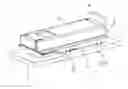
FIG. 1 is an exploded view of an electrical connector assembly according to a preferred embodiment of the present invention;
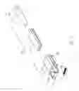
FIG. 2 is an exploded view of the support device and the other connector assembled thereon;
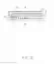
FIG. 3 is an assembled view of the electrical connector assembly with a substrate;
FIG. 4 is a cross-sectional view of the electrical connector assembly, showing the press member in a first position; and
FIG. 5 is similar to FIG. 4, showing the press member in a second position.
DETAILED DESCRIPTION OF THE INVENTION
Reference will now be made to the drawings to describe the present invention in detail.
FIGS. 1 to 3 illustrates an electrical connector assembly 100 in accordance to a preferred embodiment of the present invention, the electrical connector assembly 100 is used for electrically connecting an abutment connector or pluggable module 3 to a substrate 5. The electrical connector assembly 100 comprises an electrical connector 1 assembled to the substrate 5 and a support device (not labeled). The abutment connector 3 defines a plurality of pads 31.
Referring to FIG. 1, the electrical connector 1 includes an insulative housing 11 and a plurality of contacts 12 received therein. The insulative housing 11 includes a body portion 110 and a stop wall 111 extending upwardly from one end of the body portion 110. When the abutment connector 3 is assembled to the abutment connector 3, the abutment connector 3 restricts by the stop wall 111 to ensure the abutment connector 3 be assembled in a correct position. The contacts 12 are received in the body portion 110 of the insulative housing 11. Referring to FIG. 4, each of the contacts 12 includes a contact portion 121 extending beyond the body portion 110 of the insulative housing 11. The contact portions 121 are used for connecting with the pads 31 of the abutment connector 3.
Referring to FIGS. 1 to 3, the support device includes a support member 2 be assembled to the substrate 5 and a press member 4 assembled to the support member 2. The support member 2 is used to receive and position the abutment connector 3. The press member 4 is used to press the abutment connector 3. The support member 2 is made of metal material and includes a bottom wall 22 adjacent to the substrate 5, a top wall 21 opposite to the bottom wall 22 and a pair of opposite sidewalls 20 connecting the top wall 21 and the bottom wall 22. The top wall 21, the bottom wall 22 and the pair of sidewalls 20 form a space 211 for receiving the abutment connector 3. The bottom wall 22 includes a spring portion 221 to support the abutment connector 3 and a foot portion 222 extending downwardly to position the support member 2 on the substrate 5. The top wall 21 includes a press portion 210 for pressing the press member 4 and a stop portion 23 extending downwardly. When the abutment connector 3 is assembled to the electrical connector 3, the abutment connector 3 restricts by the stop portion 23 to ensure the abutment connector 3 be assembled in a correct position. The press member 4 includes a base portion 41 for pressing the abutment connector 3 and a handing portion 42 extending from the base portion 41.
Referring to FIGS. 3 to 4, showing the electrical connect assembly 100 is assembled to the substrate 5. The contacts 12 of the electrical connector 1 are soldered to the substrate 5 through soldering materials 13. The foot portion 222 of the support member 2 is inserted into the hole 51 of the substrate 5 to position the support member 2 on the substrate 5. The electrical connector 1 locates on one side of the bottom wall 22. In this embodiment, the top wall 21 is longer than the bottom wall 22, and the electrical connector 1 locates under the top wall 21.
Referring to FIGS. 4 to 5, showing the electrical connector assembly 100 is used. Firstly, the abutment connector 3 is pushed into the space 211 of the support member 2 in a horizontal direction, due to the abutment connector 3 being supported by the spring portion 221 of the support member 2, the pads 31 of the abutment connector 3 disconnect with the contacts 12 of the electrical connector 1, thus can protect the contacts 12 from being damaged. Secondly, the press member 4 is inserted into the space 211 of the support member 2 in a horizontal direction. The press member 4 locates on the abutment connector 3 and press the abutment connector 3. When the press member 4 is inserted into the space 211 of the support member 2, the press portion 210 of the support member 2 presses the press member 4 to make the abutment connector 3 move downwardly and the spring portion 221 of the support member 2 also moves downwardly, thus the pads 31 of the abutment connector 3 connect with the contact portions 121 of the contacts 12.
While the preferred embodiments in accordance with the present invention has been shown and described, equivalent modifications and changes known to persons skilled in the art according to the spirit of the present invention are considered within the scope of the present invention as defined in the appended claims.
Claims
What is claimed is:1. An electrical connector assembly mounted on a substrate for electrically connecting an abutment connector, comprising:
an electrical connector including a plurality of contacts; and
a support device including a support member for positioning the abutment connector being assembled in a horizontal direction and a press member assembled to the support member, the support member including a bottom wall and a top wall opposite to the bottom wall; wherein
the bottom wall includes a spring portion, when the abutment is assembled to the support member, the spring portion supports the abutment connector to make the abutment connector disconnect with the contacts, when the press member is inserted into the support member, the spring portion moves downwardly to make the abutment connector connect with the contacts.
2. The electrical connector assembly as claimed in claim 1, wherein the top wall includes a press portion extending toward the bottom wall for pressing the press member.
3. The electrical connector as claimed in claim 2, wherein the support member further includes a pair of opposite sidewalls connecting the top wall and the bottom wall, the top wall, the bottom wall and the pair of sidewalls form a space for receiving the abutment connector.
4. The electrical connector as claimed in claim 2, wherein the top wall further includes a stop portion extending downwardly to block the abutment connector.
5. The electrical connector as claimed in claim 1, wherein the bottom wall further includes a foot portion extending downwardly to position the support member on the substrate.
6. The electrical connector as claimed in claim 1, wherein the electrical connector further includes an insulative housing with a body portion for receiving the contacts, each of the contacts including a contact portion extending beyond the body portion to contact with the abutment connector.
7. The electrical connector as claimed in claim 6, wherein the insulative housing further includes a stop wall extending upwardly from one end of the body portion to block the abutment connector.
8. The electrical connector as claimed in claim 1, wherein the top wall is longer than the bottom wall, the electrical connector locates under the top wall and locates on one side of the bottom wall.
9. The electrical connector as claimed in claim 8, wherein the press member including a base portion for pressing the abutment connector and a handing portion extending upwardly from the base portion.
10. A support device mounted on a substrate for positioning an abutment connector, comprising:
a support member for positioning the abutment connector being assembled in a horizontal direction; and
a press member assembled to the support member, the support member including a bottom wall and a top wall opposite to the bottom wall; wherein
the bottom wall includes a spring portion, when the abutment is assembled to the support member, the spring portion supports the abutment connector to make the abutment connector disconnect with the contacts, when the press member is inserted into the support device, the spring portion moves downwardly to make the abutment connector connect with the contacts.
11. The support device as claimed in claim 10, wherein the top wall includes a press portion extending toward the bottom wall for pressing the press member.
12. The support device as claimed in claim 11, wherein the support member further includes a pair of opposite sidewalls connecting the top wall and the bottom wall, the top wall, the bottom wall and the pair of sidewalls form a space for receiving the abutment connector.
13. The support device as claimed in claim 11, wherein the top wall further includes a stop portion extending downwardly to block the abutment connector.
14. The support device as claimed in claim 10, wherein the bottom wall further includes a foot portion extending downwardly to position the support member on the substrate.
15. An electrical connector assembly comprising:
a printed circuit board;
an electrical connector mounted upon the printed circuit board;
a support member mounted upon the printed circuit board with a receiving space therebetween and covering said electrical connector, said receiving space forwardly communicating with an exterior via a front opening of said support device;
an upward biasing device located in the receiving space around the printed circuit board;
a pluggable module inserted into the receiving space via the front opening in a suspension manner not to connect the electrical connector; and
a press member successively actuated to invade the receiving space and oppress the upward biasing device for downwardly pressing the pluggable module upon so as to have the pluggable module mechanically and electrically connect the electrical connector.
16. The electrical connector assembly as claimed in claim 15, wherein said supporting member defines a pressing portion around a top wall thereof to downward press the press member.
17. The electrical connector assembly as claimed in claim 15, wherein said press member directly downwardly presses upon the pluggable module.
18. The electrical connector assembly as claimed in claim 15, wherein the electrical connector defines a plurality of upward conductors, and the pluggable connector defines a plurality of downward conductors for electrical connection with said upward conductors once the press member is actuated.
19. The electrical connector assembly as claimed in claim 15, wherein said press member is discrete and completely removable from the support member.
20. The electrical connector assembly as claimed in claim 19, wherein said press member is moveable relative to the support member along a front-to-back direction.
Images & Drawings included:


Sources:
- United States Patent and Trademark Office - verify current appl. status at the USPTO↗
Recent applications in this class:
- » 20250158322 2025-05-15
ROTATABLE TERMINAL MODULE - » 20240106163 2024-03-28
RETRACTABLE CONNECTOR - » 20240097379 2024-03-21
CARRIER PLATE AND ARRANGEMENTS FORMED WITH SAME - » 20230246381 2023-08-03
MANAGEMENT SYSTEM FOR ELECTRIC VEHICLE CHARGING CABLE - » 20230106493 2023-04-06
Self-aligning holster for J1772 plug used in electric vehicle supply equipment - » 20230083974 2023-03-16
Plug Protecting Device - » 20220393393 2022-12-08
POWER ADAPTER - » 20220200198 2022-06-23
Retaining module for cables - » 20220173548 2022-06-02
Tethered connector assembly - » 20220140527 2022-05-05
Gathering mechanism for adapter
Recent applications for this Assignee:
- » 20250218287 2025-07-03
METHOD OF GENERATING AND PROMPTING TRAFFIC INFORMATION, AND ROADSIDE DEVICE THEREOF - » 20250178535 2025-06-05
METHOD FOR CONSTRUCTING 3D PANORAMIC VIEW MODEL, VEHICLE-MOUNTED DEVICE, AND STORAGE MEDIUM - » 20250074444 2025-03-06
METHOD FOR EARLY WARNING A BLIND AREA, ELECTRONIC DEVICE AND STORAGE MEDIUM - » 20240416754 2024-12-19
DISPLAY CONTROL DEVICE, DISPLAY EQUIPMENT, AND VEHICLE EMPLOYING DEVICE - » 20240411051 2024-12-12
Light-emitting device array and optical transceiver system having the same - » 20240324114 2024-09-26
DISPLAY CONTROL DEVICE AND VEHICLE EMPLOYING DEVICE - » 20240295957 2024-09-05
METHOD FOR CONTROLLING ELECTRONIC DEVICE, ELECTRONIC DEVICE AND COMPUTER STROAGE MEDIUM EMPLOYING METHOD - » 20240257357 2024-08-01
METHOD FOR DETECTING OBSTACLES, ELECTRONIC DEVICE, AND STORAGE MEDIUM - » 20240203133 2024-06-20
LANE LINE RECOGNITION METHOD, ELECTRONIC DEVICE AND STORAGE MEDIUM - » 20240199157 2024-06-20
METHOD OF CONTROLLING STATE OF ELECTRIC ASSIST BICYCLE, CONTROL SYSTEM, AND ELECTRONIC DEVICE