Control valve for a camshaft adjuster
US20150129069A1
2015-05-14
14/402,561
2013-03-08
✅ Patent granted
US 9,458,942 B2
2016-10-04
WO; PCT/EP2013/054677; 20130308
WO; WO2013/174531; 20131128
John K Fristoe, Jr. | Kelsey Rohman
Volpe and Koenig, P.C.
2033-05-11
Abstract:
A control valve (4) for controlling pressure medium flows of a camshaft adjuster, which control valve includes a substantially hollow cylindrical control sleeve (6), which is disposed inside a casing (8), and a control piston (12) which is guided axially displaceably inside the control sleeve (6) against the spring force of a spring element (14), the control sleeve (6) having at one axial end a base (22) which serves as an axial contact surface for the spring element (14).
Assignee:
- SCHAEFFLER TECHNOLOGIES GMBH & CO. KG 528 🇩🇪 Herzogenaurach, Germany
- Schaeffler Technologies AG &Co. KG 4,023 🇩🇪 Herzogenaurach, Germany
Applicant:
Interested in similar patents?
Get notified when new applications in this technology area are published.
Classification:
F16K11/0716 » CPC main
Multiple-way valves, e.g. mixing valves; Pipe fittings incorporating such valves with all movable sealing faces moving as one unit comprising only sliding valves, i.e. sliding closure elements with linearly sliding closure members with cylindrical slides with fluid passages through the valve member
F01L1/344 » CPC further
Valve-gear or valve arrangements, e.g. lift-valve gear characterised by the provision of means for changing the timing of the valves without changing the duration of opening and without affecting the magnitude of the valve lift changing the angular relationship between crankshaft and camshaft, e.g. using helicoidal gear
F01L1/3442 » CPC further
Valve-gear or valve arrangements, e.g. lift-valve gear characterised by the provision of means for changing the timing of the valves without changing the duration of opening and without affecting the magnitude of the valve lift changing the angular relationship between crankshaft and camshaft, e.g. using helicoidal gear using hydraulic chambers with variable volume to transmit the rotating force
F01L2001/3443 » CPC further
Valve-gear or valve arrangements, e.g. lift-valve gear characterised by the provision of means for changing the timing of the valves without changing the duration of opening and without affecting the magnitude of the valve lift changing the angular relationship between crankshaft and camshaft, e.g. using helicoidal gear using hydraulic chambers with variable volume to transmit the rotating force; Details relating to the hydraulic feeding circuit; Oil control valves Solenoid driven oil control valves
F01L2001/34423 » CPC further
Valve-gear or valve arrangements, e.g. lift-valve gear characterised by the provision of means for changing the timing of the valves without changing the duration of opening and without affecting the magnitude of the valve lift changing the angular relationship between crankshaft and camshaft, e.g. using helicoidal gear using hydraulic chambers with variable volume to transmit the rotating force Details relating to the hydraulic feeding circuit
F01L2001/34426 » CPC further
Valve-gear or valve arrangements, e.g. lift-valve gear characterised by the provision of means for changing the timing of the valves without changing the duration of opening and without affecting the magnitude of the valve lift changing the angular relationship between crankshaft and camshaft, e.g. using helicoidal gear using hydraulic chambers with variable volume to transmit the rotating force; Details relating to the hydraulic feeding circuit Oil control valves
F01L2001/34453 » CPC further
Valve-gear or valve arrangements, e.g. lift-valve gear characterised by the provision of means for changing the timing of the valves without changing the duration of opening and without affecting the magnitude of the valve lift changing the angular relationship between crankshaft and camshaft, e.g. using helicoidal gear using hydraulic chambers with variable volume to transmit the rotating force; Details relating to the hydraulic means for changing the angular relationship Locking means between driving and driven members
F16K11/0712 » CPC further
Multiple-way valves, e.g. mixing valves; Pipe fittings incorporating such valves with all movable sealing faces moving as one unit comprising only sliding valves, i.e. sliding closure elements with linearly sliding closure members with cylindrical slides comprising particular spool-valve sealing means
F16K27/048 » CPC further
Construction of housing ; Use of materials therefor of sliding valves Electromagnetically actuated valves
F16K31/0613 » CPC further
Operating means Actuating devices; ; Releasing devices electric ; magnetic using a magnet, e.g. diaphragm valves, cutting off by means of a liquid; Multiple-way valves; Sliding valves with cylindrical slides
Y10T137/8663 » CPC further
Fluid handling; Systems; Multi-way valve unit; Supply and exhaust; Motor-operated Fluid motor
Y10T137/8671 » CPC further
Fluid handling; Systems; Multi-way valve unit; Supply and exhaust; Reciprocating valve; Piston valve With annular passage [e.g., spool]
Y10T137/86574 » CPC further
Fluid handling; Systems; Multi-way valve unit Supply and exhaust
Y10T137/86622 » CPC further
Fluid handling; Systems; Multi-way valve unit; Supply and exhaust Motor-operated
Y10T137/86694 » CPC further
Fluid handling; Systems; Multi-way valve unit; Supply and exhaust; Reciprocating valve Piston valve
Y10T137/86702 » CPC further
Fluid handling; Systems; Multi-way valve unit; Supply and exhaust; Reciprocating valve; Piston valve With internal flow passage
Y10T137/86775 » CPC further
Fluid handling; Systems; Multi-way valve unit; Dividing into parallel flow paths with recombining; Reciprocating; Spool With internal passage
F16L41/00 IPC
Branching pipes; Joining pipes to walls
F16D3/00 IPC
Yielding couplings, i.e. with means permitting movement between the connected parts during the drive
F16C11/00 IPC
Pivots; Pivotal connections
F01L1/34 IPC
Valve-gear or valve arrangements, e.g. lift-valve gear characterised by the provision of means for changing the timing of the valves without changing the duration of opening and without affecting the magnitude of the valve lift
F16K11/07 IPC
Multiple-way valves, e.g. mixing valves; Pipe fittings incorporating such valves with all movable sealing faces moving as one unit comprising only sliding valves, i.e. sliding closure elements with linearly sliding closure members with cylindrical slides
F16K31/06 IPC
Operating means Actuating devices; ; Releasing devices electric ; magnetic using a magnet, e.g. diaphragm valves, cutting off by means of a liquid
F16K11/074 IPC
Multiple-way valves, e.g. mixing valves; Pipe fittings incorporating such valves with all movable sealing faces moving as one unit comprising only sliding valves, i.e. sliding closure elements with pivoted closure members with flat sealing faces
F01L1/047 IPC
Valve-gear or valve arrangements, e.g. lift-valve gear; Valve drive by means of cams, camshafts, cam discs, eccentrics or the like Camshafts
F16K15/18 IPC
Check valves with actuating mechanism; Combined check valves and actuated valves
F16K27/04 IPC
Construction of housing ; Use of materials therefor of sliding valves
F01L5/14 » CPC further
Slide valve-gear or valve-arrangements characterised by the provision of valves with reciprocating and other movements
F01L2001/34433 » CPC further
Valve-gear or valve arrangements, e.g. lift-valve gear characterised by the provision of means for changing the timing of the valves without changing the duration of opening and without affecting the magnitude of the valve lift changing the angular relationship between crankshaft and camshaft, e.g. using helicoidal gear using hydraulic chambers with variable volume to transmit the rotating force; Details relating to the hydraulic feeding circuit; Oil control valves Location oil control valves
F15B13/04 IPC
Details of servomotor systems ; Valves for servomotor systems; Fluid distribution or supply devices characterised by their adaptation to the control of servomotors for use with a single servomotor
F01L2001/0475 » CPC further
Valve-gear or valve arrangements, e.g. lift-valve gear; Valve drive by means of cams, camshafts, cam discs, eccentrics or the like; Camshafts Hollow camshafts
F01L2001/0476 » CPC further
Valve-gear or valve arrangements, e.g. lift-valve gear; Valve drive by means of cams, camshafts, cam discs, eccentrics or the like; Camshafts Camshaft bearings
Y10T137/87169 » CPC further
Fluid handling; Systems Supply and exhaust
Description
FIELD OF THE INVENTION
The invention relates to a control valve for controlling flows of pressurized medium of a camshaft adjuster, wherein this control valve comprises an essentially hollow cylindrical control sleeve that is arranged inside a casing, and a guided control piston that can move in the axial direction inside the control sleeve against a spring force of a spring element.
BACKGROUND
In an internal combustion engine of a motor vehicle, a camshaft that is in driven connection with a crankshaft is typically used for actuating the gas exchange valves. Here it has proven advantageous to be able to change the opening and closing times of the gas exchange valves while the internal combustion engine is running. By adjusting the opening and closing times, for example, as a function of the current rotational speed, in particular, the fuel consumption can be reduced, the exhaust gas behavior can be positively influenced, and the engine efficiency can be increased.
The variability of the gas exchange valve control times is usually achieved through a relative change of the phase position of the camshaft relative to the crankshaft. For this purpose, typically a so-called camshaft adjuster is integrated into the drive train by means of which the torque is transferred from the crankshaft to the camshaft. The mounting of modern camshaft adjusters is located, for example, on the drive-side end of the camshaft, on an intermediate shaft, on a non-rotating component, or on the crankshaft.
The crankshaft adjuster is here constructed such that, during the operation, the phase position between the crankshaft and camshaft can be reliably maintained and if necessary the camshaft can be rotated in a certain angle range relative to the crankshaft. For this purpose, the camshaft adjuster is formed essentially with at least two pressure chambers acting against each other. Through targeted connection of the pressure chambers with a pressurized medium pump or with a pressurized medium tank, the phase of the camshaft can be adjusted or maintained relative to the crankshaft.
The pressurized medium supply to the pressure chambers and the pressurized medium discharge from the pressure chambers is usually controlled by means of a control valve, usually in the form of a multiple-path gate valve. This typically comprises, as essential components, a control sleeve and a control piston that is held in the control sleeve so that it can move in the axial direction against the spring force of a spring element and that is actuated by an actuator, typically an electromagnet. The control valve also has, in particular, a pressurized medium connection, a discharge connection and work connections by means of which the pressurized medium can be injected into a pressure chamber or discharged out from a pressure chamber. For the switchable distribution of the pressurized medium to the work connections, a casing is further provided that has corresponding pressurized medium channels to a pressure chamber that can be actuated by means of the control piston. Depending on the position of the control piston, for example, one of the pressure chambers is connected to the supply connection via one of the work connections and is filled with pressurized medium. At the same time, the opposing pressure chamber communicates via the work connection allocated to it with the discharge connection on the control valve and is in this way emptied.
In one common construction, such a control valve is constructed, for example, as a so-called central valve that is inserted into a central hole of the camshaft adjuster and is screwed to the camshaft.
A control valve of the type noted above is known, for example, from DE 10 2010 026 853 A1 or from DE 10 2008 004 591 A1. According to DE 10 2008 004 591 A1, the control valve is inserted into a central screw that is screwed to a camshaft under attachment, on its part, of the camshaft adjuster.
To be able to withstand the mechanical loads during the operation of the control valve, in the control valve according to DE 10 2008 004 591 A1, a solid, shaped spring receptacle that is supported on the casing is provided for supporting the spring element. A solid spring receptacle that forms part of the casing is also formed in the control valve corresponding to DE 10 2010 026 853 A1.
From DE 10 2009 051 519 A1 it is further known to provide a separate spring plate that is supported, on its side, on the casing, for supporting the spring element.
SUMMARY
The present invention is based on the objective of forming a control valve of the type noted above to the extent that it enables the simplest and most economical production possible.
The stated objective is met according to the invention for a control valve of the type noted above such that the control sleeve has, at one axial end, a base that is used as an axial contact surface for the spring element.
The invention here starts, in a first step, from the idea that a spring receptacle made from the casing is associated with additional material expense. The casing is usually made from a plastic, so that a corresponding solid construction is required. According to DE 10 2010 026 853 A1, the counter support formed by the spring receptacle of the casing is also supported by means of a reinforced section of the control sleeve. The use of a separate component for supporting the spring element represents, in turn, an additional production and installation step that increases the costs of the control valve.
In a second step, the invention recognizes that the a counter support can be formed for supporting the spring element in a surprisingly simple way such that the control sleeve is formed on an axial end with a base, wherein the base is used as an axial contact surface for the spring element. The control sleeve is typically made from a metal. The base can be formed, in particular, with a non-cutting process, for example, by a deep-drawing process. For installation, the control sleeve merely has to be inserted into the casing. Because the base can be supported by a surface on the casing, no additional material must be added to the casing.
In a preferred construction, the base has a recess through which a projection of the casing passes in the axial direction for a positive locking connection. This construction offers the advantage that the casing is used simultaneously as a guide or stabilization aid for the spring element. For example, the projection can have a pin-like construction and can act as a receptacle element for a helical spring. The pin projection centers the helical spring when it is inserted. At the same time, it forms a side guide for the mounted spring element. Through the positive locking engagement of the casing through the recess, the control sleeve is further fixed in the control valve.
Advantageously, the recess is formed with a multiple-fold, cyclic rotational symmetry, in particular, in the shape of a flower. Through multiple-fold rotational symmetry, it is achieved, with comparatively simple production, that the control sleeve is rotationally locked in the casing. A multiple-fold, cyclic rotational symmetry is given, for example, by a recess that is formed as a polygon. For a flower-shaped construction, contact areas on which the spring element is supported project inward between “leaf-shaped” recesses.
As another advantage, the invention provides that the base of the control sleeve can be used simultaneously as an axial counter support for a non-return valve. In this case, the use of an additional counter support for the non-return valve is eliminated. If an engagement of the casing through a recess in the base of the control sleeve is provided, then this engagement can preferably have a hollow construction. The non-return valve can then be supported on contact surfaces of the base extending inwards in the radial direction opposite the material of the “engagement.”
BRIEF DESCRIPTION OF THE DRAWINGS
Embodiments of the invention are explained in more detail below with reference to a drawing. Shown are:
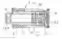
FIG. 1: in a cross section, a control valve for a hydraulic camshaft adjuster,
FIG. 2: in a cross section, a control sleeve made from the control valve according to FIG. 1, and
FIG. 3: in a top view, the base of the control sleeve according to FIG. 2.
DETAILED DESCRIPTION OF THE PREFERRED EMBODIMENTS
In FIG. 1, a control valve 4 in the form of a central valve is shown in a cross section. The control valve 4 can be inserted in a central hole of a camshaft adjuster or in a central screw. The control valve 4 essentially comprises a control sleeve 6 that is held in a casing 8. A control piston 12 is supported in the interior of the control sleeve 6 so that it can move in the axial direction. The control piston 12 is here pretensioned by means of a spring element 14. From the drawn position, the control piston 12 can be pushed into the control sleeve 6 against the spring force of the spring element 14.
To actuate the control piston 12, an actuator, for example, an electromagnet with a plunger, can engage the outer end side of this control piston in the axial direction. An axial sliding of the control piston 12 or control sleeve 6 from the casing 8 caused, in particular, by the spring force of the spring element 14 is prevented by a securing ring.
In the view provided, a pressurized medium space 16 that is formed between the control piston 12 and the control sleeve 6 and is connected to a pressurized line of the hydraulic system, for example, via an axial hole in the camshaft or in a central screw, can be seen. For this purpose, radial holes 18 that are connected to axial grooves 20 in the casing 8 in terms of flow are formed in the control sleeve 6. On their part, the grooves 20 are connected to the described axial hole in terms of flow.
On one axial end, the control sleeve 6 is formed with a base 22. This base 22 forms an axial contact surface for the spring element 14. The shown helical spring directly contacts the base 22 with one end. The other end of the helical spring acts against a collar in the interior of the control piston 12.
A recess 24 is formed in the base 22. A projection 25 that is formed as part of the casing 8 extends through this recess 24. The control sleeve 6 is made from a metal. The casing 8 is produced from plastic using a non-cutting method by a shaping process.
To discharge a hydraulic fluid, outlets 28 that open into a tank outlet T of the hydraulic system are provided on the end side of the control piston 12.
In FIG. 2, the control sleeve 6 corresponding to FIG. 1 is shown in a cross section. Visible here are the radial holes 18 that are loaded directly with pressure from a pressurized medium line. Furthermore, the base 22 is visible in the control sleeve 6. A central recess 24 that has a multiple-fold, cyclic rotational symmetry is formed in the base 22. Accordingly, the control sleeve 6 according to FIG. 1 is locked in rotation with the casing 8.
Furthermore, according to FIG. 2, work connections A, B for the opposing pressurized medium chambers of a camshaft adjuster can be seen on the control sleeve 6. By shifting the control piston 12 according to FIG. 1, the work connections A, B are alternately connected to the pressurized medium space 16 in terms of flow.
In FIG. 3, in a top view, the base 22 of the control sleeve 6 according to FIG. 2 is shown. Visible is the central recess 24 of the base 22 constructed with a flower-like shape with a 4-fold cyclic rotational symmetry. Through the flower shape, overall four contact surfaces 30 are formed that extend radially inward and on which the spring element 14 corresponding to FIG. 1 is supported.
The construction of the base 22 according to FIG. 3 is also suitable, in particular, as a counter support for a not-shown non-return valve. For this purpose, for example, the projection 25 according to FIG. 1 can have a hollow construction, so that the non-return valve in FIG. 1 in also supported from the right on the base 22 of the control sleeve 6.
LIST OF REFERENCE NUMBERS
- 4 Control valve
- 6 Control sleeve
- 8 Casing
- 12 Control piston
- 14 Spring element
- 16 Pressurized medium space
- 18 Radial hole
- 20 Groove
- 22 Base
- 24 Recess
- 25 Projection
- 28 Outlet
- 30 Contact surfaces
Claims
1. A control valve for controlling flows of pressurized medium of a camshaft adjuster, said control valve comprises an essentially hollow cylindrical control sleeve arranged inside a casing and a guided control piston that is movable in an axial direction inside the control sleeve against a spring force of a spring element, the control sleeve has, on an axial end, a base that is an axial contact surface for the spring element.
2. The control valve according to claim 1, wherein the base comprises a recess through which a projection of the casing passes in the axial direction in a positive locking connection.
3. The control valve according to claim 2, wherein the recess is formed with a multiple-fold, cyclic rotational symmetry.
4. The control valve according to claim 1, wherein the base of the control sleeve simultaneously forms an axial counter support for a non-return valve.
Images & Drawings included:


Sources:
- United States Patent and Trademark Office - verify current appl. status at the USPTO↗
Similar patent applications:
- » 20080149056
Camshaft adjuster control valve arrangement - » 20190353061
CONTROL VALVE FOR A CAMSHAFT ADJUSTER - » 20150204217
Control valve of a camshaft adjuster - » 20150267571
Control valve for a camshaft adjuster system - » 20160334022
Control valve for a camshaft adjuster - » 20180187578
Control valve for a camshaft adjuster - » 20180266286
CONTROL VALVE FOR A CAMSHAFT ADJUSTER - » 20090134349
Control valve for a camshaft adjuster - » 20090159829
Control valve for a camshaft adjuster - » 20100294387
Control valve for a camshaft adjuster
Recent applications in this class:
- » 20250207673 2025-06-26
DIRECTIONAL VALVE - » 20250109755 2025-04-03
VALVE SYSTEMS - » 20250067351 2025-02-27
HYDRAULIC VALVE SPOOL THROUGH WHICH A FLUID CAN FLOW, BIDIRECTIONAL CONTROL VALVE, AND METHOD - » 20240344619 2024-10-17
Multi-Port Valve for Water Treatment - » 20240328521 2024-10-03
ELECTRO-MAGNETIC THERMAL CONTROL VALVE - » 20240200669 2024-06-20
TEMPERATURE CONTROL SYSTEM, VEHICLE, ENERGY STORAGE SYSTEM, AND MULTI-PORT VALVE - » 20230407976 2023-12-21
AXIAL THREE-WAY MODULATING VALVE - » 20230332694 2023-10-19
LOW FORCE VALVES FOR DRUG DELIVERY PUMPS - » 20230220916 2023-07-13
Flow control system and method for controlling the flow of liquid - » 20230213111 2023-07-06
Pump, multi-function valve, and controller apparatus
Recent applications for this Assignee:
- » 20250293624 2025-09-18
METHOD FOR DETERMINING AN INITIAL ROTOR POSITION OF A ROTOR, COMPUTER PROGRAM PRODUCT, CONTROL UNIT, ELECTRIC MACHINE, INSPECTION AND/OR TEST METHOD AND TEST STAND - » 20250290560 2025-09-18
TORQUE CONVERTER WITH PULLING BIAS SPRING - » 20250283516 2025-09-11
FREEWHEEL DEVICE AND FREEWHEEL CLUTCH - » 20250279708 2025-09-04
HYBRID DRIVE RESOLVER ROTOR MOUNTING ARRANGEMENT - » 20250273375 2025-08-28
DETENT SOLENOID - » 20250269726 2025-08-28
Electrical Circuit, On-Board Power Supply System, Vehicle, Method, Computer Program, And Computer-Readable Medium - » 20250269694 2025-08-28
ADJUSTMENT MECHANISM COMPRISING A LINEAR ACTUATOR, VEHICLE AND METHOD FOR OPERATING A VEHICLE - » 20250264157 2025-08-21
PLANETARY GEARBOX HAVING A ROTATIONALLY FIXED THRUST WASHER OF THE PLANET BEARING - » 20250263129 2025-08-21
WHEEL WELL GUARD FOR A WHEEL WELL OF A VEHICLE AND VEHICLE HAVING THE WHEEL WELL GUARD - » 20250262941 2025-08-21
Individual Monitoring Of A Plurality Of Output Points Of A System For The Vehicle-Based Supply Of External Loads