Method of composing a sleeve assembly for containment purposes in high centrifugal applications
US20150145369A1
2015-05-28
14/406,705
2013-03-15
✅ Patent granted
US 10,965,197 B2
2021-03-30
WO; PCT/IB2013/000401; 20130315
WO; WO2013/160739; 20131031
Jacob T Minskey | Caroline Montiel
Bacon & Thomas, PLLC
2036-10-05
Abstract:
This invention relates to a method for composing a sleeve assembly suitable for use in containment purposes in high-speed machine that are subjected to high operational temperatures. The method has the steps of providing a composite sleeve and winding at least two layers of woven fabric on top of the composite sleeve and each other, where the woven fabric is impregnated with a thermoset resin. The method additionally has the step of optionally winding a perforated layer on top of an outermost layer of the layers of woven fabric to remove excess resin when the woven fabric is wound over the composite sleeve. The method also includes the steps of wrapping an absorption layer over the composite sleeve for absorbing the excess resin, curing the thermoset resin, and removing the absorption layer and the perforated layer after the curing.
Assignee:
- Atlas Copco Airpower, Naamloze Vennootschap 272 🇧🇪 WILRIJK, Belgium
- ATLAS COPCO AIRPOWER, N.V. 22 🇧🇪 Wilrijk, Belgium
Applicant:
Interested in similar patents?
Get notified when new applications in this technology area are published.
Classification:
B29C70/347 » CPC further
Shaping composites, i.e. plastics material comprising reinforcements, fillers or preformed parts, e.g. inserts comprising reinforcements only, e.g. self-reinforcing plastics; Shaping operations therefor; Shaping by lay-up, i.e. applying fibres, tape or broadsheet on a mould, former or core; Shaping by spray-up, i.e. spraying of fibres on a mould, former or core and shaping or impregnating by compression, i.e. combined with compressing after the lay-up operation combined with compressing after the winding of lay-ups having a non-circular cross-section, e.g. flat spiral windings
B32B5/024 » CPC further
Layered products characterised by the non- homogeneity or physical structure, i.e. comprising a fibrous, filamentary, particulate or foam layer; Layered products characterised by having a layer differing constitutionally or physically in different parts characterised by structural features of a layer Woven fabric
B32B37/142 » CPC further
Methods or apparatus for laminating, e.g. by curing or by ultrasonic bonding characterised by the properties of the layers Laminating of sheets, panels or inserts, e.g. stiffeners, by wrapping in at least one outer layer, or inserting into a preformed pocket
B29L2023/001 » CPC further
Tubular articles Tubular films, sleeves
B29L2031/748 » CPC further
Other particular articles Machines or parts thereof not otherwise provided for
B32B3/266 » CPC further
Layered products comprising a layer with external or internal discontinuities or unevennesses, or a layer of non-planar form ; Layered products having particular features of form characterised by a particular shape of the outline of the cross-section of a continuous layer; characterised by a layer with cavities or internal voids ; characterised by an apertured layer characterised by an apertured layer, the apertures going through the whole thickness of the layer, e.g. expanded metal, perforated layer, slit layer regular cells
B32B2260/023 » CPC further
Layered product comprising an impregnated, embedded, or bonded layer wherein the layer comprises an impregnation, embedding, or binder material; Composition of the impregnated, bonded or embedded layer; Fibrous or filamentary layer Two or more layers
B29C70/42 » CPC further
Shaping composites, i.e. plastics material comprising reinforcements, fillers or preformed parts, e.g. inserts comprising reinforcements only, e.g. self-reinforcing plastics; Shaping operations therefor; Shaping or impregnating by compression not applied for producing articles of definite length, i.e. discrete articles
B32B2260/046 » CPC further
Layered product comprising an impregnated, embedded, or bonded layer wherein the layer comprises an impregnation, embedding, or binder material; Impregnation, embedding, or binder material Synthetic resin
B32B2307/51 » CPC further
Properties of the layers or laminate having particular mechanical properties Elastic
B32B2307/726 » CPC further
Properties of the layers or laminate; Other properties Permeability to liquids, absorption
B32B2307/736 » CPC further
Properties of the layers or laminate; Other properties; Dimensional properties; Dimensional stability Shrinkable
B32B2307/748 » CPC further
Properties of the layers or laminate; Other properties Releasability
B32B2597/00 » CPC further
Tubular articles, e.g. hoses, pipes
H02K15/03 » CPC main
Methods or apparatus specially adapted for manufacturing, assembling, maintaining or repairing of dynamo-electric machines of stator or rotor bodies having permanent magnets
B32B37/14 IPC
Methods or apparatus for laminating, e.g. by curing or by ultrasonic bonding characterised by the properties of the layers
B32B37/26 » CPC further
Methods or apparatus for laminating, e.g. by curing or by ultrasonic bonding characterised by the properties of the layers with at least one layer which influences the bonding during the lamination process, e.g. release layers or pressure equalising layers
H02K1/28 » CPC further
Details of the magnetic circuit characterised by the shape, form or construction; Rotating parts of the magnetic circuit Means for mounting or fastening rotating magnetic parts on to, or to, the rotor structures
B32B38/10 » CPC further
Ancillary operations in connection with laminating processes Removing layers, or parts of layers, mechanically or chemically
H02K15/12 » CPC further
Methods or apparatus specially adapted for manufacturing, assembling, maintaining or repairing of dynamo-electric machines Impregnating, heating or drying of windings, stators, rotors or machines
H02K1/27 IPC
Details of the magnetic circuit characterised by the shape, form or construction; Rotating parts of the magnetic circuit Rotor cores with permanent magnets
B32B5/12 » CPC further
Layered products characterised by the non- homogeneity or physical structure, i.e. comprising a fibrous, filamentary, particulate or foam layer; Layered products characterised by having a layer differing constitutionally or physically in different parts characterised by structural features of a layer characterised by the relative arrangement of fibres or filaments of different layers, e.g. the fibres or filaments being parallel or perpendicular to each other
B32B5/26 » CPC further
Layered products characterised by the non- homogeneity or physical structure, i.e. comprising a fibrous, filamentary, particulate or foam layer; Layered products characterised by having a layer differing constitutionally or physically in different parts characterised by the presence of two or more layers which are next to each other and are fibrous, filamentary, formed of particles or foamed one layer being a fibrous or filamentary layer another layer also being fibrous or filamentary
B32B5/02 IPC
Layered products characterised by the non- homogeneity or physical structure, i.e. comprising a fibrous, filamentary, particulate or foam layer; Layered products characterised by having a layer differing constitutionally or physically in different parts characterised by structural features of a layer
B32B3/26 IPC
Layered products comprising a layer with external or internal discontinuities or unevennesses, or a layer of non-planar form ; Layered products having particular features of form characterised by a particular shape of the outline of the cross-section of a continuous layer; characterised by a layer with cavities or internal voids ; characterised by an apertured layer
B32B27/12 » CPC further
Layered products comprising synthetic resin next to a fibrous or filamentary layer
B29C70/34 » CPC further
Shaping composites, i.e. plastics material comprising reinforcements, fillers or preformed parts, e.g. inserts comprising reinforcements only, e.g. self-reinforcing plastics; Shaping operations therefor; Shaping by lay-up, i.e. applying fibres, tape or broadsheet on a mould, former or core; Shaping by spray-up, i.e. spraying of fibres on a mould, former or core and shaping or impregnating by compression, i.e. combined with compressing after the lay-up operation
B32B1/08 » CPC further
Layered products having a general shape other than plane Tubular products
Description
BACKGROUND OF THE INVENTION
1. Field of the invention
This invention relates to a method of composing a sleeve assembly comprising a composite sleeve, said sleeve assembly being suitable to be used for containment purposes in high-speed machines and subjected to high operational temperatures, such as 160° C. or higher.
2. Discussion of the Related Art
Possible use for such sleeve assemblies would be to keep permanent magnets in a precompressed state at all speeds. A mounting procedure of such sleeve assemblies has been described in U.S. patent application No. 2011/0099793 A1, which is incorporated by reference.
At high centrifugal loads it is important to maintain compression between layers of a composite sleeve in order to prevent delamination and detachment of fibers. For this purpose a hoop layer is normally used as an external layer of such a containment sleeve.
High operational temperature requires the use of thermally stable polymers, but such polymers are comparatively brittle. Therefore composite sleeves made of such polymers are more prone to internal delamination and damage during assembly with shrink-fits approaching or even exceeding 1%. Such high shrink-fits are used to provide contact pressures with a composite sleeve of minimal thickness. Since every layer contributes to the contact pressure imposed by the sleeve, the intermediate layers become sandwiched between the top layer of the sleeve and, for example, a rotor around which the sleeve is being provided. So unwinding of the sleeve would always start at the top layer of the sleeve.
A hoop layer is most commonly used as an external layer, because it has high radial stiffness and thus provides the necessary contact pressure. However fibers in such a layer are oriented in parallel and there is little interlinkage between them. Fibers located at the side of the external hoop layer are the least supported or least interlinked fibers in the sleeve and therefore serve as an origin for unwinding.
SUMMARY OF THE INVENTION
In this invention a solution for this problem is proposed. It is suggested to wind at least two layers of a bidirectional woven fabric on top of the sleeve. There is a considerable amount of interlinkage between fibers which solves the problem of unwinding. Although only the outer layer is adjusted in such a sleeve, the overall performance of the sleeve substantially improves, as unwinding is one of the restricting factors for performance of such containment sleeves.
There are different ways for applying the composite sleeve for reinforcement:
-
- 1) A bidirectional fabric preimpregnated with semi-cured thermoset resin could be wound on top of a premade composite sleeve. The prepreg should preferably have a similar thermal limit as the epoxy used during winding of the composite sleeve. This method is fairly simple and is applied easily. However, extra costs are associated with this method due to the use of this prepreg material and the costs for curing the prepreg.
- 2) A dry bidirectional fabric could be impregnated with the same type of resin as the one used during winding of the composite sleeve and wrapped around the premade composite sleeve. Use of the same type of resin will ensure thermal compatibility of the external layer and the rest of the composite sleeve. The expression “of the same type” used throughout this text, means that the resins are of identical composition and physical properties, however, the invention is in no way limited as such.
- 3) A dry bidirectional fabric could be impregnated with the same type of resin as the one used during winding of the composite sleeve and wrapped around the wet composite sleeve. If the fabric is sufficiently light, it could also be impregnated with excess resin coming out to the surface of the composite sleeve during winding. The use of the same type of resin will ensure good bonding between layers and provide the same thermal limit for the whole composite sleeve.
Winding with a broad fabric requires special equipment and most filament winding machines are not able to wind such fabric. It is also not a trivial task to apply pretension to the fabric as it is done with fiber tows during wet filament winding. So if winding is followed by wrapping and no additional measures are applied, the outer layer of the sleeve would have fairly low fiber content.
Performance of composite materials is greatly affected by the fiber content. For example, a composite tube with increased fiber content has an equivalent increase in radial stiffness per thickness. So the required contact pressure could be achieved with smaller thickness of the composite sleeve. Thickness reduction of composite sleeves is of particular importance in permanent magnet machines as this helps to increase power density and overall efficiency of the motor through the increase of the flux density in the air-gap of the motor.
Additionally, in many containment applications it is important to achieve a smooth surface. For instance, in case of high speed machines, roughness on the surface of the composite sleeve may cause additional friction losses and excessive heating of the sleeve.
A smooth finish can be achieved by keeping the excess resin on the surface of the sleeve. It is worth noting that since epoxy expands during curing of the composite the outer epoxy layer could become excessively thick and prone to damage during assembly and detachment at high speeds.
The following method could be applied to solve the aforementioned problems. A layer of perforated shrink tape is wound on top of the outer layer of the sleeve in order to provide a smooth finish, but also arranged so that excessive epoxy is removable from the outer layer.
Alternatively, a layer of a perforated plastic could be put on top of the sleeve in order to provide an exit path for excess resin, for example, a single layer of perforated shrink tape could be applied on top of the sleeve. Of course, a few layers of conventional shrink tape could be wound and then a few passes of a roller with pins could be rolled around the wound shrink tape in order to create holes. However this leads to damage of underneath fibers and deteriorates performance of the composite, which is critical for highly loaded containment sleeves. For that reason it is better to use a perforated plastic.
Additionally, a layer or a few layers of a peel-ply can then be wrapped over the sleeve in order to absorb excessive epoxy that is bled through the holes of the perforated plastic layer. On top of the layer of peel-ply additional layers of non-perforated shrink tape can be wound in order to create an outer pressure on the outer surface of the composite sleeve during curing. This method is particularly effective for large pipes, because with increased diameter contact pressure exerted by a single layer of shrink tape proportionally reduces. So in order to achieve sufficient pressure on the outer surface, additional layers of shrink tape or alternative measures for application of external pressure are necessary.
This method would also be applicable for an external layer made of prepregs, because external pressure helps to increase the fiber content and remove air-pockets. Since prepregs are applied on a premade sleeve, larger external pressures would be possible. In order to achieve good quality of prepreg-based composites, it is suggested to use pressures in excess of 3-5 bar in order to reach high fiber content. This requires the use of an autoclave, which is not always available or applicable. Recent investigations reveal that the drying out of fibers in epoxy based composites does not start until pressures of 13-15 bar are reached and optimal pressures in this regard are equal to 10 bar. As the method suggested in this invention does not impose limitation on the outer pressure other then the stiffness and the strength of the premade sleeve itself, a highly competitive quality of the composite can be achieved.
This method is also applicable for an external layer made of a wet fabric and wrapped around a premade composite sleeve. As in the previous case, this layer becomes squeezed between the premade sleeve and the layers of tape wound on top of the external layer of wet fabric. Again no limit on external pressures is applicable other then the stiffness and the strength of the premade sleeve itself.
In order to diminish production costs, shrink tape can be substituted by any reusable preferably elastic tape which is configured to achieve the required contact pressure on the outer surface of the sleeve. After curing this elastic tape can be removed and reused. In order to avoid contamination of said tape with excess resin an intermediate protective layer of conventional plastic could be wound on top of the layers of peel-ply.
BRIEF DESCRIPTION OF THE DRAWINGS
The present invention is illustrated with the intention of better showing the characteristics of the invention, as an example without being limitative in any way, to describe a method for composing a sleeve assembly with reference to the accompanying figures:
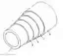
FIG. 1 schematically represents a perspective view of a sleeve assembly during its manufacturing process.
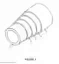
FIG. 2 schematically represents the process for composing a sleeve assembly used for containment purposes in high-speed machines.
DESCRIPTION OF THE PREFERRED EMBODIMENT
FIG. 1 shows a composite sleeve 1, for example, obtained through filament winding.
On top of said composite sleeve 1 are provided two layers of woven fabric 2. According to a preferred characteristic of the invention, at least one of said layers of woven fabric 2 comprises bidirectional woven fabric. The invention, however, is not limited as such to include the bidirectional woven fabric.
Preferably, each of a first plurality of fibres making part of said woven fabric extends in a respective plane extending perpendicularly to a longitudinal central axis of said composite sleeve 1. A second plurality of fibres making part of said woven fabric 2 preferably extends crosswise with respect to the direction of said first plurality of fibres.
In case use is made of a bidirectional woven fabric 2, the angle between the directions of said first and second plurality of fibres is preferably 90°, however, also other angles are possible, such as for example an angle of approximately 60°.
According to the invention, as seen in FIG. 2, while carrying out the composition method, a perforated layer 3, for example perforated plastic film or shrink tape, is provided on top of the outermost surface of said layers of woven fabric 2.
Additionally, an absorption layer 4 is provided on said perforated layer 3. The absorption layer 4 preferably, but not necessarily comprises a peel-ply.
Advantageously, an external pressure layer 5, for example a layer of shrink tape of elastic tape, can further be provided on said absorption layer 4 to create a pressure on the outer surface of the composite sleeve.
After the resin in the layers of woven fabric 2 has been cured and set, the pressure layer 5, absorption layer 4 and perforated layer 3 are removed and the sleeve assembly is provided.
The present invention is by no way limited to the forms of embodiment described above and depicted in the drawings. A method according to the invention of composing a sleeve assembly, and a sleeve assembly obtained by such method, can realized in different ways, without departure from the scope of the invention.
Claims
1-18. (canceled)
19. A method of composing a sleeve assembly used for containment purposes in high-speed machines that is subjected to high operational temperatures, said method comprising the steps of:
providing a composite sleeve;
winding at least two layers of woven fabric on top of said composite sleeve and each other, said woven fabric being impregnated with a thermoset resin;
winding a perforated layer on top of an outermost layer of said layers of woven fabric to remove excess resin from the woven fabric when the woven fabric is wound over the composite sleeve, said perforated layer being configured to provide an exit path for excess resin;
wrapping an absorption layer over the composite sleeve for absorbing said excess resin from the exit path of the perforated layer;
curing said thermoset resin while maintaining a pressure on said woven fabric; and
removing said absorption layer and said perforated layer after said curing.
20. The method of claim 19, wherein at least one of said layers of woven fabric are pre-impregnated with a semi-cured thermoset resin.
21. The method of claim 19, wherein at least one of said layers of woven fabric is impregnated with the same type of resin as the one used during winding of the composite sleeve.
22. The method of claim 19, wherein the composite sleeve upon which the layers of woven fabric are applied, comprises a wet composite sleeve that has not yet or only partially been cured; and wherein said composite sleeve and the resin in said layers of woven fabric are cured together.
23. The method of claim 19, wherein said perforated layer consists of a pre-perforated layer.
24. The method of claim 19, wherein the step of applying said perforated layer comprises the substeps of applying a layer on top of said layers of woven fabric, and subsequently providing perforations in said layer.
25. The method of claim 19, wherein said perforated layer comprises a perforated shrink tape or a layer of perforated plastic.
26. The method of claim 19, wherein said absorption layer comprises at least one layer of a peel-ply.
27. The method of claim 19, wherein the pressure on the layers of woven fabric during curing, is provided by the pre-tension of the one or more layers of a peel-ply.
28. The method of claim 19, further comprising the steps of applying a pressure layer on top of said absorption layer, before curing said resin and of removing said pressure layer after said curing.
29. The method of claim 19, wherein said pressure layer comprises one or more layers of shrink tape or elastic tape.
30. The method of claim 19, further comprising the step of providing an intermediate, removable protective layer between said absorption layer and said pressure layer.
31. A sleeve assembly composed through the method of claim 19, said sleeve assembly to be used for containment purposes in high-speed machines that is subjected to high operational temperatures, said sleeve assembly comprising:
a composite sleeve;
at least two layers of woven fabric on top of said composite sleeve.
32. The sleeve assembly of claim 31, wherein at least one of said layers of woven fabric comprises bidirectional woven fabric.
33. The sleeve assembly of claim 31, wherein a first plurality of fibres making part of said woven fabric extend in respective plane extending perpendicularly to a longitudinal central axis of said sleeve assembly.
34. The sleeve assembly of claim 33, wherein a second plurality of fibres making part of said woven fabric extend crosswise with respect to said first plurality of fibres.
35. The sleeve assembly of claim 34, wherein the angle between the directions of the first and second plurality fibres is 90°.
36. A high speed permanent magnet motor comprising a rotor with permanent magnets, wherein a sleeve assembly according to claim 31 is provided around said permanent magnets.
Images & Drawings included:

Sources:
- United States Patent and Trademark Office - verify current appl. status at the USPTO↗
Recent applications in this class:
- » 20250219513 2025-07-03
STEPPER MOTOR MAGNET PIN INSERTION PROCESS - » 20250192652 2025-06-12
WINDING APPARATUS FOR A ROTOR CORE - » 20250175063 2025-05-29
METHOD FOR MANUFACTURING ROTOR AND APPARATUS FOR MANUFACTURING ROTOR - » 20250167646 2025-05-22
SYSTEM AND MANUFACTURING METHOD FOR ASSEMBLING A LAMINATION STACK WITH A TWO-COMPONENT ADHESIVE AT LOWER TEMPERATURES - » 20250167645 2025-05-22
MAGNETIC ALIGNMENT SYSTEMS AND METHODS FOR PERMANENT MAGNET MOTORS - » 20250149957 2025-05-08
ROTOR MANUFACTURING METHOD AND ROTOR - » 20250141324 2025-05-01
METHOD FOR OBTAINING A ROTOR FOR A ROTARY ELECTRIC MACHINE - » 20250132648 2025-04-24
MAGNET INSERTION DEVICE - » 20250132647 2025-04-24
MAGNET UNIT AND METHOD FOR MANUFACTURING THE SAME - » 20250132646 2025-04-24
HALBACH ARRAY ASSEMBLING METHOD FOR MOTOR ROTOR AND ROTOR FOR MOTOR
Recent applications for this Assignee:
- » 20250290714 2025-09-18
METHOD FOR CONTROLLING A COMPRESSOR INSTALLATION AND COMPRESSOR INSTALLATION - » 20250290568 2025-09-18
FOUR-WAY VALVE AND DRYER PROVIDED WITH SUCH A FOUR-WAY VALVE - » 20250224000 2025-07-10
METHOD OF REGULATING ELECTRICAL SUPPLY FOR A MAGNETIC BEARING CONTROL SYSTEM - » 20250215870 2025-07-03
DEVICE FOR COMPRESSING A GAS AND METHOD OF ASSEMBLING SUCH DEVICE - » 20250198451 2025-06-19
ROTATIONAL ELEMENT AND COMPRESSOR ASSEMBLY COMPRISING SUCH A ROTATIONAL ELEMENT - » 20250177914 2025-06-05
COMPRESSOR INSTALLATION AND METHOD FOR DELIVERING A COMPRESSED GAS - » 20250165887 2025-05-22
METHOD FOR IMPROVING THE EFFICIENCY AND/OR INCREASING THE OPERATIONAL SCOPE OF A SYSTEM FOR PRESSURIZED FLUID COMPRISING A PRESSURIZED PIPING NETWORK UNDER DYNAMIC LOAD - » 20250146486 2025-05-08
METHOD FOR CONTROLLING A FIRST REFERENCE TEMPERATURE IN A DEVICE FOR COMPRESSING GAS - » 20250131150 2025-04-24
OPTIMIZATION OR IMPROVEMENT OF THE EFFICIENCY OF A SYSTEM FOR PRESSURIZED FLUID COMPRISING A PRESSURIZED PIPING NETWORK UNDER DYNAMIC LOAD - » 20250122877 2025-04-17
COMPRESSOR ASSEMBLY COMPRISING A MOTOR DRIVING ONE OR MORE COMPRESSOR ROTORS AND METHOD FOR FABRICATING A HOUSING PART OF SUCH A COMPRESSOR ASSEMBLY