Keyboard for supporting electronic device
US20150169078A1
2015-06-18
14/518,830
2014-10-20
✅ Patent granted
US 9,298,272 B2
2016-03-29
-
-
Anthony Q Edwards
Novak Druce Connolly Bove + Quigg LLP
2034-10-20
Abstract:
A keyboard for supporting an electronic device includes a keyboard body and an adjusting device. The keyboard body defines a receiving portion for receiving an electronic device, a first adjusting hole, and a second adjusting hole. The adjusting device includes a stopping plate received in the receiving portion, a first adjusting pole, and a second adjusting pole. The first adjusting pole extends out of the first adjusting hole to abut against the stopping plate. The second adjusting pole extends out of the second adjusting hole to abut against the stopping plate. An angle is defined between the first adjusting pole and the electronic device and the angle is adjustable based on the first adjusting pole and the second adjusting pole being mounted to a plurality of positions.
Assignee:
- ScienBiziP Consulting(Shenzhen)Co., Ltd. 48 🇨🇳 Shenzhen, China
Applicant:
Interested in similar patents?
Get notified when new applications in this technology area are published.
Classification:
G06F3/0219 » CPC main
Input arrangements for transferring data to be processed into a form capable of being handled by the computer; Output arrangements for transferring data from processing unit to output unit, e.g. interface arrangements; Input arrangements or combined input and output arrangements for interaction between user and computer; Input arrangements using manually operated switches, e.g. using keyboards or dials; Constructional details or processes of manufacture of the input device Special purpose keyboards
G06F1/1626 » CPC further
Details not covered by groups - and; Constructional details or arrangements for portable computers with a single-body enclosure integrating a flat display, e.g. Personal Digital Assistants [PDAs]
G06F1/1632 » CPC further
Details not covered by groups - and; Constructional details or arrangements for portable computers External expansion units, e.g. docking stations
G06F3/0202 » CPC further
Input arrangements for transferring data to be processed into a form capable of being handled by the computer; Output arrangements for transferring data from processing unit to output unit, e.g. interface arrangements; Input arrangements or combined input and output arrangements for interaction between user and computer; Input arrangements using manually operated switches, e.g. using keyboards or dials Constructional details or processes of manufacture of the input device
G06F1/16 IPC
Details not covered by groups - and Constructional details or arrangements
G06F3/02 IPC
Input arrangements for transferring data to be processed into a form capable of being handled by the computer; Output arrangements for transferring data from processing unit to output unit, e.g. interface arrangements; Input arrangements or combined input and output arrangements for interaction between user and computer Input arrangements using manually operated switches, e.g. using keyboards or dials
Description
CROSS-REFERENCE TO RELATED APPLICATIONS
This application claims priority to Chinese Patent Application No. 201310672596.5 Dec. 12, 2013, the contents of which are incorporated by reference herein.
FIELD
The subject matter herein generally relates to a keyboard for supporting an electronic device.
BACKGROUND
A keyboard can be used to support an electronic device.
BRIEF DESCRIPTION OF THE DRAWINGS
Implementations of the present technology will now be described, by way of example only, with reference to the attached figures.
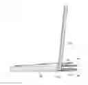
FIG. 1 is an exploded, isometric view of an embodiment of a keyboard for supporting an electronic device.
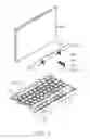
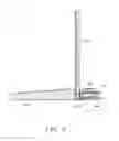
FIG. 2 is an assembled, isometric view of the keyboard of FIG. 1.
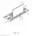
FIG. 3 is similar to FIG. 2, but viewed from a different angle.
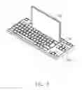
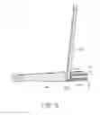
FIG. 4 is a cutaway, cross sectional view along a line IV-IV of FIG. 2, and the electronic member is in a first position.
FIG. 5 is similar to FIG. 4, but the electronic member is in a second position.
DETAILED DESCRIPTION
It will be appreciated that for simplicity and clarity of illustration, where appropriate, reference numerals have been repeated among the different figures to indicate corresponding or analogous elements. In addition, numerous specific details are set forth in order to provide a thorough understanding of the embodiments described herein. However, it will be understood by those of ordinary skill in the art that the embodiments described herein can be practiced without these specific details. In other instances, components have not been described in detail so as not to obscure the related relevant feature being described. Also, the description is not to be considered as limiting the scope of the embodiments described herein. The drawings are not necessarily to scale and the proportions of certain parts have been exaggerated to better illustrate details and features of the present disclosure.
Several definitions that apply throughout this disclosure will now be presented.
The term “coupled” is defined as connected, whether directly or indirectly through intervening components, and is not necessarily limited to physical connections. The connection can be such that the objects are permanently connected or releasably connected. The term “substantially” is defined to be essentially conforming to the particular dimension, shape, or other feature that the term modifies, such that the component need not be exact. For example, “substantially cylindrical” means that the object resembles a cylinder, but can have one or more deviations from a true cylinder. The term “comprising,” when utilized, means “comprising, but not necessarily limited to”; it specifically indicates open-ended inclusion or membership in the so-described combination, group, series, and the like.
The present disclosure is described in relation to a keyboard for supporting an electronic device.
FIG. 1 illustrates an embodiment of a keyboard 300 for supporting an electronic device 100. The keyboard 300 comprises a keyboard body 30 and an adjusting device 40. In one embodiment, each the electronic device 100 and the keyboard 300 are substantially rectangular.
The keyboard body 30 defines a receiving portion 32, a first adjusting hole 34, and a second adjusting hole 36. Each the first adjusting hole 34 and the second adjusting hole 36 are coupled to the receiving portion 32. Each the first adjusting hole 34 and the second adjusting hole 36 defines an inner screw thread (not labeled).
The adjusting device 40 comprises a stopping plate 42, a first adjusting pole 44, and a second adjusting pole 46. The stopping plate 42 comprises a plate body 422 and a plurality of elastic members 424. The elastic members 424 are secured on the plate body 422 and are substantially perpendicular to the plate body 422. Each the first adjusting pole 44 and the second adjusting pole 46 define an outer screw thread 48 (shown in FIG. 4). In one embodiment, the stopping plate 42 is substantially rectangular and each elastic member 424 is a spring.
FIGS. 2 and 3 illustrate that in assembly, the stopping plate 42 is received in the receiving portion 32. The first adjusting pole 44 extends out of the first adjusting hole 34 to abut against the plate body 422. The second adjusting pole 46 extends out of the second adjusting hole 36 to abut against the plate body 422. The first adjusting pole 44 and the second adjusting pole 46 are substantially parallel to each other and are substantially perpendicular to the plate body 422. The elastic members 424, the first adjusting pole 44, and the second adjusting pole 46 are located on the same side of the plate body 422. The elastic members 424 are substantially parallel to the first adjusting pole 44 and the second adjusting pole 46. One end of the electronic member 100 is received in the receiving portion 32 and abuts on the plate body 422. The inner screw thread of the first adjusting hole 34 is matched to and receives the outer screw thread 48 of the first adjusting pole 44. The inner screw thread of the second adjusting hole 36 is matched to and receives the outer screw thread 48 of the second adjusting pole 46. A first angle is defined between the first adjusting pole 44 and the electronic device 100. A second angle is defined between the second adjusting pole 46 and the electronic device 100. The first angle is equal to the second angle.
FIGS. 4 and 5 illustrate that, in use, the first adjusting pole 44 and the second adjusting pole 46 can be mounted to different positions to abut against the plate body 422, thereby the plate body 422 can abut against the electronic device 100, thus the electronic device 100 can be rotated to a plurality of positions, and the first angle and the second angle can be changed. The first angle and the second angle can be acute, a right angle, or obtuse.
It is to be understood that even though numerous characteristics and advantages have been set forth in the foregoing description of embodiments, together with details of the structures and functions of the embodiments, the disclosure is illustrative only and changes may be made in detail, especially in the matters of shape, size, and arrangement of parts within the principles of the disclosure to the full extent indicated by the broad general meaning of the terms in which the appended claims are expressed.
Claims
What is claimed is:1. A keyboard for supporting an electronic device comprising:
a keyboard body having:
a receiving portion configured to receive an electronic device,
a first adjusting hole coupled to the receiving portion, and
a second adjusting hole coupled to the receiving portion, and
an adjusting device comprising:
a stopping plate configured to be received in the receiving portion,
a first adjusting pole extending out of the first adjusting hole to abut against the stopping plate, and
a second adjusting pole extending out of the second adjusting hole to abut against the stopping plate;
wherein a first angle is defined between the first adjusting pole and the electronic device and the first angle is adjustable based on the stopping plate abutting against the electronic device when the first adjusting pole and the second adjusting pole are mounted to a plurality of positions.
2. The keyboard of claim 1, wherein the first adjusting hole defines an inner screw thread, the first adjusting pole defines an outer screw thread.
3. The keyboard of claim 1, wherein a second angle is defined between the second adjusting pole and the electronic device and the second angle is adjustable based on the first adjusting pole and the second adjusting pole being mounted to a plurality of positions.
4. The keyboard of claim 3, wherein the first angle is equal to the second angle.
5. The keyboard of claim 1, wherein the second adjusting hole defines an inner screw thread, the second adjusting pole defines an outer screw thread.
6. The keyboard of claim 1, wherein the stopping plate comprises a plate body and an elastic member, one end of the elastic member is secured to the plate body, and the other end of the elastic member abuts against the keyboard body.
7. The keyboard of claim 6, wherein the elastic member is substantially perpendicular to the plate body.
8. The keyboard of claim 6, wherein the elastic member is substantially parallel to the first adjusting pole.
9. The keyboard of claim 6, wherein the elastic member, the first adjusting pole, and the second adjusting pole are located on the same side of the plate body.
10. The keyboard of claim 1, wherein the first angle is substantially acute.
11. A keyboard for supporting an electronic device comprising:
a keyboard body having:
a receiving portion configured receive an end of an electronic device,
a first adjusting hole coupled to the receiving portion, and
an adjusting device comprising:
a stopping plate configured to be received in the receiving portion, and
a first adjusting pole received in the first adjusting hole and abutting against the stopping plate;
wherein the first adjusting pole can be mounted to a plurality of positions to abut against the stopping plate, thereby the stopping plate can abut against the electronic device, thus the electronic device can rotate to a plurality of positions.
12. The keyboard of claim 11, wherein the keyboard body further defines a second adjusting hole, the adjusting device further comprises a second adjusting pole received in the second adjusting hole and abutting against the stopping plate, the first adjusting pole and the second adjusting pole can be mounted to a plurality of positions to abut against the stopping plate, thereby the stopping plate can abut against the electronic device, thus the electronic device can rotate to a plurality of positions.
13. The keyboard of claim 12, wherein the second adjusting hole defines an inner screw thread, the second adjusting pole defines an outer screw thread.
14. The keyboard of claim 12, wherein the first adjusting pole and the second adjusting pole are substantially parallel to each other.
15. The keyboard of claim 12, wherein a second angle is defined between the second adjusting pole and the electronic device and the second angle is adjustable based on the second adjusting pole being mounted to a plurality of positions.
16. The keyboard of claim 15, wherein a second angle is defined between the first adjusting pole and the electronic device, the first adjusting pole and the second adjusting pole can be mounted to a plurality of positions to change the first angle and the second angle, and the first angle is equal to the second angle.
17. The keyboard of claim 16, wherein the second angle is substantially acute.
18. The keyboard of claim 15, wherein the first angle can be obtuse or rectangular.
19. The keyboard of claim 11, wherein the stopping plate comprises a plate body and an elastic member, one end of the elastic member is secured to the plate body, and the other end of the elastic member abuts against the keyboard body.
20. The keyboard of claim 19, wherein the elastic member is substantially parallel to the first adjusting pole.
Images & Drawings included:
Sources:
- United States Patent and Trademark Office - verify current appl. status at the USPTO↗
Similar patent applications:
Recent applications in this class:
- » 20250258550 2025-08-14
KEYBOARD DEVICE, CONTROL METHOD, AND NON-TRANSITORY RECORDING MEDIUM - » 20250244832 2025-07-31
INFORMATION HANDLING SYSTEM ASSYMETRIC DISPLAY FOLD TO SUPPORT AN ADAPTIVE KEYBOARD ROW - » 20250216954 2025-07-03
ETHIOPIC SINGLE TO THREE KEYSTROKES TYPING - » 20250190059 2025-06-12
VISUALLY INDICATIVE KEYBOARD - » 20250130651 2025-04-24
System for Improving User Input Recognition on Touch Surfaces - » 20250093966 2025-03-20
Customizable Human Interface Device - » 20250085789 2025-03-13
ONE-HANDED INPUT DEVICE - » 20250068256 2025-02-27
KEYBOARD LETTER AREA LAYOUT METHOD - » 20250060834 2025-02-20
MULTI-FUNCTIONAL KEY MODULE - » 20250021171 2025-01-16
Reconfigurable Keyboard
Recent applications for this Assignee:
- » 20190094416 2019-03-28
Gas permeable ophthalmic lens material and gas permeable ophthalmic lens of such material - » 20190000359 2019-01-03
Ophthalmic lens with glucose sensitive pad and method for manufacturing same - » 20180117799 2018-05-03
Method for forming film - » 20180044501 2018-02-15
Method for making colored film, colored film, colored material, and ophthalmic lens - » 20170336043 2017-11-23
Lighting structure - » 20170334065 2017-11-23
Intelligent robot with different accouterments - » 20170254680 2017-09-07
High density sensor module - » 20170103034 2017-04-13
Motherboard and computer control system including the same - » 20170080875 2017-03-23
Fastening apparatus - » 20160349815 2016-12-01
Wireless communication system and network attached storage device thereof