System and method for user input
US20150172536A1
2015-06-18
14/132,869
2013-12-18
✅ Patent granted
US 9,557,905 B2
2017-01-31
-
-
Sath V Perungavoor | Janese Duley
2034-12-26
Abstract:
A medical diagnostic imaging system comprises a user interface comprising at least one physical control. The system also comprises a camera positioned to view the physical control. The system further comprises a processor connected to the camera and configured to detect a manipulation involving the physical control and associate the manipulation with a desired user input for controlling the imaging system.
Assignee:
- GENERAL ELECTRIC COMPANY 28,775 🇺🇸 Schenectady, NY, United States
Applicant:
Interested in similar patents?
Get notified when new applications in this technology area are published.
Classification:
H04N5/23219 » CPC main
Details of television systems; Studio circuitry; Studio devices; Studio equipment ; Cameras comprising an electronic image sensor, e.g. digital cameras, video cameras, TV cameras, video cameras, camcorders, webcams, camera modules for embedding in other devices, e.g. mobile phones, computers or vehicles; Television cameras ; Cameras comprising an electronic image sensor, e.g. digital cameras, video cameras, camcorders, webcams, camera modules specially adapted for being embedded in other devices, e.g. mobile phones, computers or vehicles; Devices for controlling television cameras, e.g. remote control ; Control of cameras comprising an electronic image sensor; Control of camera operation based on recognized objects where the recognized objects include parts of the human body, e.g. human faces, facial parts or facial expressions
H04N5/23216 » CPC further
Details of television systems; Studio circuitry; Studio devices; Studio equipment ; Cameras comprising an electronic image sensor, e.g. digital cameras, video cameras, TV cameras, video cameras, camcorders, webcams, camera modules for embedding in other devices, e.g. mobile phones, computers or vehicles; Television cameras ; Cameras comprising an electronic image sensor, e.g. digital cameras, video cameras, camcorders, webcams, camera modules specially adapted for being embedded in other devices, e.g. mobile phones, computers or vehicles; Devices for controlling television cameras, e.g. remote control ; Control of cameras comprising an electronic image sensor Control of parameters, e.g. field or angle of view of camera via graphical user interface, e.g. touchscreen
G06F3/017 » CPC further
Input arrangements for transferring data to be processed into a form capable of being handled by the computer; Output arrangements for transferring data from processing unit to output unit, e.g. interface arrangements; Input arrangements or combined input and output arrangements for interaction between user and computer Gesture based interaction, e.g. based on a set of recognized hand gestures
H04N5/232 IPC
Details of television systems; Studio circuitry; Studio devices; Studio equipment ; Cameras comprising an electronic image sensor, e.g. digital cameras, video cameras, TV cameras, video cameras, camcorders, webcams, camera modules for embedding in other devices, e.g. mobile phones, computers or vehicles; Television cameras ; Cameras comprising an electronic image sensor, e.g. digital cameras, video cameras, camcorders, webcams, camera modules specially adapted for being embedded in other devices, e.g. mobile phones, computers or vehicles Devices for controlling television cameras, e.g. remote control ; Control of cameras comprising an electronic image sensor
G06F3/0484 IPC
Input arrangements for transferring data to be processed into a form capable of being handled by the computer; Output arrangements for transferring data from processing unit to output unit, e.g. interface arrangements; Input arrangements or combined input and output arrangements for interaction between user and computer; Interaction techniques based on graphical user interfaces [GUI] for the control of specific functions or operations, e.g. selecting or manipulating an object, an image or a displayed text element, setting a parameter value or selecting a range
A61B8/467 » CPC further
Diagnosis using ultrasonic, sonic or infrasonic waves; Ultrasonic, sonic or infrasonic diagnostic devices with special arrangements for interfacing with the operator or the patient characterised by special input means
G06F3/011 » CPC further
Input arrangements for transferring data to be processed into a form capable of being handled by the computer; Output arrangements for transferring data from processing unit to output unit, e.g. interface arrangements; Input arrangements or combined input and output arrangements for interaction between user and computer Arrangements for interaction with the human body, e.g. for user immersion in virtual reality
G06F3/0233 » CPC further
Input arrangements for transferring data to be processed into a form capable of being handled by the computer; Output arrangements for transferring data from processing unit to output unit, e.g. interface arrangements; Input arrangements or combined input and output arrangements for interaction between user and computer; Input arrangements using manually operated switches, e.g. using keyboards or dials; Arrangements for converting discrete items of information into a coded form, e.g. arrangements for interpreting keyboard generated codes as alphanumeric codes, operand codes or instruction codes Character input methods
G06F3/0304 » CPC further
Input arrangements for transferring data to be processed into a form capable of being handled by the computer; Output arrangements for transferring data from processing unit to output unit, e.g. interface arrangements; Input arrangements or combined input and output arrangements for interaction between user and computer; Arrangements for converting the position or the displacement of a member into a coded form Detection arrangements using opto-electronic means
G06F3/0426 » CPC further
Input arrangements for transferring data to be processed into a form capable of being handled by the computer; Output arrangements for transferring data from processing unit to output unit, e.g. interface arrangements; Input arrangements or combined input and output arrangements for interaction between user and computer; Arrangements for converting the position or the displacement of a member into a coded form; Digitisers, e.g. for touch screens or touch pads, characterised by the transducing means by opto-electronic means using a single imaging device like a video camera for tracking the absolute position of a single or a plurality of objects with respect to an imaged reference surface, e.g. video camera imaging a display or a projection screen, a table or a wall surface, on which a computer generated image is displayed or projected tracking fingers with respect to a virtual keyboard projected or printed on the surface
A61B8/54 » CPC further
Diagnosis using ultrasonic, sonic or infrasonic waves Control of the diagnostic device
G06F3/01 IPC
Input arrangements for transferring data to be processed into a form capable of being handled by the computer; Output arrangements for transferring data from processing unit to output unit, e.g. interface arrangements Input arrangements or combined input and output arrangements for interaction between user and computer
G06F3/03 IPC
Input arrangements for transferring data to be processed into a form capable of being handled by the computer; Output arrangements for transferring data from processing unit to output unit, e.g. interface arrangements; Input arrangements or combined input and output arrangements for interaction between user and computer Arrangements for converting the position or the displacement of a member into a coded form
G06F3/042 IPC
Input arrangements for transferring data to be processed into a form capable of being handled by the computer; Output arrangements for transferring data from processing unit to output unit, e.g. interface arrangements; Input arrangements or combined input and output arrangements for interaction between user and computer; Arrangements for converting the position or the displacement of a member into a coded form; Digitisers, e.g. for touch screens or touch pads, characterised by the transducing means by opto-electronic means
A61B8/00 IPC
Diagnosis using ultrasonic, sonic or infrasonic waves
G06F3/04847 » CPC main
Input arrangements for transferring data to be processed into a form capable of being handled by the computer; Output arrangements for transferring data from processing unit to output unit, e.g. interface arrangements; Input arrangements or combined input and output arrangements for interaction between user and computer; Interaction techniques based on graphical user interfaces [GUI] for the control of specific functions or operations, e.g. selecting or manipulating an object, an image or a displayed text element, setting a parameter value or selecting a range Interaction techniques to control parameter settings, e.g. interaction with sliders or dials
G06F3/023 IPC
Input arrangements for transferring data to be processed into a form capable of being handled by the computer; Output arrangements for transferring data from processing unit to output unit, e.g. interface arrangements; Input arrangements or combined input and output arrangements for interaction between user and computer; Input arrangements using manually operated switches, e.g. using keyboards or dials Arrangements for converting discrete items of information into a coded form, e.g. arrangements for interpreting keyboard generated codes as alphanumeric codes, operand codes or instruction codes
Description
BACKGROUND OF THE INVENTION
The subject matter disclosed herein relates to medical diagnostic imaging systems, such as an ultrasound imaging system, and more particularly to a user input system for such imaging systems.
Cleaning and sterilizing the user interface of a medical diagnostic imaging system, such as an ultrasound system, can be a challenge. The chemicals used to clean and sterilize can hinder the operation of and even damage electronic components and controls. Different approaches have been employed in attempt to solve this problem. For example, tempered glass touch sensitive interfaces have been employed. However, this attempted solution suffers from the disadvantage that an operator, such as an ultrasound sonographer, may find it difficult to control the ultrasound system with one hand while viewing the image on the display as they are scanning the subject with a probe held in the other hand. This is because the operator must often and repeatedly look away from the display to the control panel to change the settings of the system. Having controls that the operator can identify by touch without looking at them may allow the operator to better focus on the images or behavior of the system while simultaneously modifying various settings because there is less need to look at the controls.
Therefore, a system and method of controlling a medical diagnostic imaging system that can be easily sterilized without fear of damage to electrical components and easily operated by an operator without repeatedly looking at the controls is desired.
BRIEF DESCRIPTION OF THE INVENTION
The above-mentioned shortcomings, disadvantages and problems are addressed herein which will be understood by reading and understanding the following specification.
In an embodiment a medical diagnostic imaging system comprises a user interface comprising at least one physical control. The system also comprises a camera positioned to view the physical control. The system further comprises a processor connected to the camera and configured to detect a manipulation involving the physical control and associate the manipulation with a desired user input for controlling the imaging system.
In another embodiment, a method for controlling a medical diagnostic imaging comprises providing a user interface comprising at least one physical control and viewing with a camera the physical control. The method further comprises detecting with a processor a manipulation of the physical control, and associating the manipulation with a desired user input for controlling the imaging system.
Various other features, objects, and advantages of the invention will be made apparent to those skilled in the art from the accompanying drawings and detailed description thereof.
BRIEF DESCRIPTION OF THE DRAWINGS
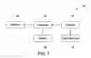
FIG. 1 is a schematic diagram of a medical diagnostic imaging system in accordance with an embodiment of the disclosure;
FIG. 2 is a top view of an ultrasound system in accordance with an embodiment of the disclosure;
FIG. 3 is a perspective view of an ultrasound system in accordance with an embodiment of the disclosure; and
FIG. 4 is a flow diagram illustrating a method for controlling a medical diagnostic imaging system.
DETAILED DESCRIPTION OF THE INVENTION
In the following detailed description, reference is made to the accompanying drawings that form a part hereof, and in which is shown by way of illustration specific embodiments that may be practiced. These embodiments are described in sufficient detail to enable those skilled in the art to practice the embodiments, and it is to be understood that other embodiments may be utilized and that logical, mechanical, electrical and other changes may be made without departing from the scope of the embodiments. The following detailed description is, therefore, not to be taken as limiting the scope of the invention.
FIG. 1 is a schematic diagram of a medical diagnostic imaging system 10 in accordance with an embodiment of the disclosure. The medical diagnostic imaging system 10 will hereinafter be described and illustrated as an ultrasound system. It should be appreciated, however, that other types of medical diagnostic imaging systems may be envisioned for implementing various embodiments of the invention. The ultrasound system 10 comprises a user interface 12. The user interface 12 may be used to control the ultrasound system 10.
FIG. 2 is a top view of the ultrasound system 10 in accordance with an embodiment of the disclosure. In the illustrated embodiment, the user interface 12 comprises a plurality of physical controls 11 and 13-17, but may also comprise an electronic control 18, or a combination thereof. It should be appreciated that physical controls identified by reference numerals 11 and 13-17 are exemplary and each may be positioned in various locations within the user interface 12.
The ultrasound system 10 also comprises a camera 20. The camera 20 may be an optical camera or an infrared camera designed to pick up ambient light in the environment. Alternatively, the camera 20 may be designed to detect light (e.g., LED) from a projector positioned to project on the physical controls. The camera 20 may be integrated into the ultrasound system 10, or may be separately attachable to the exterior of the ultrasound system 20 or even mounted to a shelf, wall or another fixture positioned nearby the system 20. The camera 20 may be positioned in proximity to the user interface 12 and configured to view a manipulation involving the physical controls 11 and 13-17. Additionally, it should be appreciated that ultrasound system 10 may comprise more than one camera 20 in order to more robustly view a variety of user manipulations.
The ultrasound system 10 further comprises a processor 24 which is electrically connected to the camera 20, memory 26 and display 28. In this context, the term “electrically connected” (and obvious variants such as “electronic connection”) refers to a wired connection for conveying electronic signals (which may be digital or analog) from one device or component to another. In one embodiment, the processor 24 may be electrically connected to at least a portion of user interface 12 when the user interface 12 comprises the electronic control 18. By contrast, the physical controls 11 and 13-17 are not electrically connected to the processor 24 and do not themselves generate electronic signals. Instead, the processor 24 is configured to receive images from the camera 20 and to analyze such images for detecting a manipulation of the physical controls 11 and 13-17. The processor 24 is further configured to associate the manipulation with a desired user input for the ultrasound system 10. The processor 24 may also be configured to control the display 28.
The memory 26 may be a non-transitory computer readable storage medium. Memory 26 is configured to store a reference set of manipulations and at least one mapping between each of those manipulations and associated user inputs for the ultrasound system 10. The memory 26 may contain additional data, instructions or programs.
Display 28 is configured to display and convey information to a user. For example, in one embodiment the display 28 is configured to display an ultrasound image. In another embodiment, the display 28 is configured to convey setting information relating to the ultrasound system 10. For example, a user could replace the user interface 12 with an alternative, modularized, user interface comprising a different arrangement of physical controls that may be mapped to additional manipulations. In yet another embodiment, the display 28 is configured to convey information about a current mapping between the manipulations and desired user inputs as applied by the processor 24 so the user can understand such mapping and optionally modify it.
Each of the physical controls 11 and 13-17 may be movable or immovable. Various embodiments of movable physical controls may be envisioned. In one embodiment, the physical controls 11 and 14 comprise buttons that are configured to be depressed and automatically return to their raised positions once downward pressure from the user ceases or, alternatively, one or both of them may toggle between raised and lowered positions on alternate presses by the user. In another embodiment, the physical control 15 comprises a plurality of depressible buttons or keys that form a keyboard. In another embodiment, the physical control 13 is a rotatable knob that is configured to be rotated about an axis. In another embodiment, the physical control 16 is a slider, configured to be moved back and forth along a line. In yet another embodiment, the physical control 17 is a trackball that is configured to rotate about a point. It should be appreciated, however, that additional embodiments of the physical control 11 may be envisioned.
Manipulation of the movable physical controls may comprise actual movements. For example, the actual movement may comprise sliding, rotating, pushing/pulling, rolling, or a combination thereof. It should be appreciated that other movements may be envisioned. Alternately, the manipulation may comprise a gesture about or in proximity to the movable controls. The gesture may comprise a sliding motion, a rotating motion, a pushing/pulling motion, a rolling motion, or a combination thereof. It should be appreciated, however, that other gestures about or in proximity to the movable physical controls may be envisioned.
One or more of the physical controls 11 and 13-17 may alternatively be immovable. Various embodiments of immovable physical controls are envisioned. For example, the buttons 11 and 14, the knob 13, the keyboard 15, the slider 16, and the trackball 17 may be stationary rather than movable. Since actual movement of an immovable physical control is not possible, the manipulation of the immovable physical control may be a gesture done by the user in the same manner as if the control were movable. The gesture may comprise a sliding motion, a rotating motion, a pushing/pulling motion, a rolling motion, or a combination thereof. It should be appreciated, however, that other gestures about or in proximity to the immovable physical controls may be envisioned.
Optionally, one or more of the physical controls 11 and 13-17 could include indicia to facilitate the processor 24 recognizing the manipulation. For example, the indicia could comprise printed text, a particular color, pattern or a surface texture that is easily recognized by the processor 24.
The user interface 12 may also comprise the electronic control 18. Unlike the physical controls 11 and 13-17, the electronic control 18 is electrically connected to processor 24. Manipulation of the electronic control 18 by a user may generate an electronic input to control the ultrasound system 10. For example, in one embodiment, the electronic control 18 may comprise a touchscreen, wherein the touchscreen comprises a plurality of soft keys configured to receive a user manipulation and generate an electronic signal that is conveyed to the processor 24.
FIG. 3 is a perspective view of the ultrasound system 10 in accordance with an embodiment of the disclosure. As described with respect to FIG. 1, the ultrasound system 10 may comprise user interface 12, camera 20 and display 28. The camera 20 is positioned in proximity to the user interface 12 to view and/or record user interaction with the user interface 12. Specifically, the camera 20 is positioned to view and/or record user manipulation of the physical controls 11 and 13-17. In the depicted embodiment, the camera 20 is positioned vertically above and to the anterior side of the user interface 12. However, it should be appreciated that other positions of the camera 20 with respect to the user interface 12 may be envisioned. For example, the camera 20 may be positioned laterally with respect to the user interface 12.
Having described the components of the ultrasound system 10, an exemplary method 400 for controlling the medical diagnostic imaging system 10 will now be described in connection with FIG. 4. The method 400 may include a step 410 comprising providing ultrasound system 10 with the user interface 12 including the physical controls 11 and 13-17. As discussed with reference to FIGS. 2 and 3, the physical controls 11 and 13-17 may be movable or immovable. The physical controls 11 and 13-17 may comprise, for example, various combinations of knobs, buttons, keyboards, sliders, trackballs, or similar input devices that are well known to operators of such systems.
The method 400 may also include a step 420 comprising viewing with a camera 20 the physical controls 11 and 13-17. The camera 20 may be positioned in proximity to the user interface 12. For example, the camera 20 may be positioned vertically above and to the anterior side of the user interface 12. In another embodiment, the camera 20 may be positioned to a lateral side of the user interface 12. The camera 20 is configured to view a manipulation of the physical controls 11 and 13-17.
The method 400 may also include a step 430 comprising detecting with the processor 24 a manipulation of the physical controls 11 and 13-17. The processor is electrically connected to camera 20 and is configured to receive images from the camera 20. The manipulation may comprise an actual movement of the physical controls 11 and 13-17 or, alternatively, a gesture by the user related to the physical controls 11 and 13-17. The movement may include sliding, rotating, pushing/pulling, rolling, or a combination thereof. It should be appreciated that other movements may be envisioned. Movement of the physical controls 11 and 13-17 may be detected based on a change of position thereof. The gesture may include a sliding motion, a rotating motion, a pushing/pulling motion, a rolling motion, or a combination thereof. It should be appreciated, however, that other gestures about or in proximity to the movable physical controls 11 and 13-17 may be envisioned. In an example, the processor 24 may detect movement of button 14 based on a change of position of an indentation thereon. In another example, the processor 24 may detect rotation of knob 13 based on a change of position of a protrusion thereon. In yet another example, the processor 24 may detect a typing gesture as if keyboard 15 were movable even when it is immovable.
The method 400 may also include a step 440 comprising associating the manipulation with a desired user input for controlling the ultrasound system. The memory 26 is configured to store a reference set of manipulations as well as a current mapping between such manipulations and associated user inputs for controlling the ultrasound system 10. The memory 26 may contain additional data, instructions or programs. For example, an actual depression (or simply a user gesture of depressing) of button 14 may be associated with selecting a portion of on an image on the display 28. In another example, rotating (or simply a user gesture of rotating) knob 13 may be associated with zooming in on a selected image on the display 28.
This written description uses examples to disclose the invention, including the best mode, and also to enable any person skilled in the art to practice the invention, including making and using any devices or systems and performing any incorporated methods. The patentable scope of the invention is defined by the claims, and may include other examples that occur to those skilled in the art. Such other examples are intended to be within the scope of the claims if they have structural elements that do not differ from the literal language of the claims, or if they include equivalent structural elements with insubstantial differences from the literal language of the claims.
Claims
I claim:1. A medical diagnostic imaging system, comprising:
a user interface comprising at least one physical control;
a camera positioned to view the physical control; and
a processor connected to the camera and configured to detect a manipulation involving the physical control and associate the manipulation with a desired user input for controlling the imaging system.
2. The system of claim 1, wherein the physical control comprises one of a knob, a button, a slider, and a trackball.
3. The system of claim 1, wherein the physical control is movable and the manipulation involves actual movement of the physical control.
4. The system of claim 3, wherein the physical control comprises indicia configured to facilitate detection of the manipulation by the processor.
5. The system of claim 4, wherein the indicia is selected from a text, a color, a pattern, or a surface texture.
6. The system of claim 1, wherein the physical control is immovable and the manipulation involves a gesture as if the physical control were movable.
7. The system of claim 6, wherein the gesture is a sliding motion, a rotating motion, a pushing motion or a rolling motion.
8. The system of claim 1, wherein the physical control lacks electronic connection to the processor.
9. The system of claim 1, wherein the association of the manipulation with the desired user input is modifiable.
10. The system of claim 1, wherein the camera is integrated into the system.
11. The system of claim 1, wherein the camera is separately attachable to the exterior of the system.
12. The system of claim 1, wherein the user input controls an ultrasound system.
13. A method for controlling a medical diagnostic imaging system comprising:
providing a user interface comprising at least one physical control,
viewing with a camera the physical control,
detecting with a processor a manipulation of the physical control, and
associating the manipulation with a desired user input for controlling the imaging system.
14. The method of claim 13, wherein the physical control lacks electrical connection to the processor.
15. The method of claim 13, wherein the physical control comprises one of a knob, a button, a slider, and a trackball.
16. The method of claim 13, wherein the physical control is movable and the manipulation involves actual movement of the physical control.
17. The method of claim 16, wherein the physical control comprises indicia configured to facilitate detection of the manipulation by the processor.
18. The method of claim 13, wherein the physical control is immovable and the manipulation involves a gesture as if the physical control were movable.
19. The method of claim 18, wherein the gesture is a sliding motion, a rotating motion, a pushing motion or a rolling motion.
20. The method of claim 13, wherein the user input controls an ultrasound system.
Images & Drawings included:


Sources:
- United States Patent and Trademark Office - verify current appl. status at the USPTO↗
Similar patent applications:
- » 20230289017
User-input systems and methods of detecting a user input at a cover member of a user-input system - » 20230004245
User-input systems and methods of detecting a user input at a cover member of a user-input system - » 20220187919
User-input systems and methods of delineating a location of a virtual button by haptic feedback and of determining user-input - » 20230195232
User-input systems and methods of delineating a location of a virtual button by haptic feedback and of determining user-input - » 20180333641
Smart user input devices, and systems and methods for monitoring such smart user input devices - » 20150169287
ARTIFICIAL INTELLIGENCE USER INPUT SYSTEMS AND METHODS - » 20170123509
USER INPUT SYSTEM AND METHOD COMPRISING AN INTERCHANGEABLE GRAPHIC MODULE HAVING GRAPHICAL MARKINGS - » 20050166161
User input system and method for selecting a file - » 20060044282
User input apparatus, system, method and computer program for use with a screen having a translucent surface - » 20100222115
Multi-mode user input system and method
Recent applications in this class:
- » 20240233150 2024-07-11
FRAMING IN A VIDEO SYSTEM USING DEPTH INFORMATION - » 20240147048 2024-05-02
Updating zoom properties of corresponding salient objects - » 20240137641 2024-04-25
Framing in a video system using depth information - » 20240098359 2024-03-21
Gesture control during video capture - » 20230421884 2023-12-28
Detection of image sensor shutter state - » 20230396869 2023-12-07
Dynamic image processing method, electronic device, and terminal device connected thereto - » 20230388620 2023-11-30
Visual feature based video effects - » 20230379567 2023-11-23
SYSTEM AND TECHNIQUES FOR REFLECTION REDUCTION IN VIDEO DATA - » 20230362474 2023-11-09
Systems and methods for event-based playback control during virtual application of accessories - » 20230328357 2023-10-12
Electronic device, control method thereof, and recording medium
Recent applications for this Assignee:
- » 20250250942 2025-08-07
Overall Engine Efficiency Rating for Turbomachine Engines - » 20250243827 2025-07-31
MULTIPLE-FLOW AIRCRAFT TURBINE ENGINE - » 20250229333 2025-07-17
SYSTEMS AND METHODS FOR SMOOTHING A CONTOUR OF AN OBJECT FORMED DURING ADDITIVE MANUFACTURING - » 20250224115 2025-07-10
TURBINE ENGINE HAVING A COMBUSTION SECTION WITH A FUEL SUPPLY ASSEMBLY - » 20250223929 2025-07-10
UNDUCTED PROPELLER GAS TURBINE COMPRISING A COOLING AIR CHANNEL AND A VARIABLE BLEED VALVE EJECTION CHANNEL - » 20250222519 2025-07-10
ADDITIVE MANUFACTURING SUPPORTS AND METHODS FOR USING SAME IN ADDITIVELY MANUFACTURING PARTS - » 20250215830 2025-07-03
SUSPENSION OF A TRIPLE-FLOW AIRCRAFT TURBINE ENGINE - » 20250215826 2025-07-03
GAS TURBINE ENGINE - » 20250215811 2025-07-03
SYSTEMS AND METHODS FOR ATTACHMENT OF MATERIALS HAVING DIFFERENT THERMAL EXPANSION COEFFICIENTS - » 20250207534 2025-06-26
GAS TURBINE ENGINES AND EPICYCLIC GEARBOXES WITH PLANET GEAR CLEARANCES