Bonded sheet molding composite automotive components without surface pre-treatment
US20150191001A1
2015-07-09
14/662,631
2015-03-19
✅ Patent granted
US 10,286,642 B2
2019-05-14
-
-
William P Bell
Raymond L. Coppiellie | MacMillan, Sobanski & Todd, LLC
2036-06-07
Abstract:
An automotive assembly comprises a sheet molding composite (SMC) element comprising an SMC sheet body shaped into a generally smooth functional section and at least one generally planar bonding section. The bonding section comprises a textured surface impressed as a result of molding the SMC sheet body in a compression molding tool having a corresponding textured pattern. The textured surface has a predetermined surface roughness for increasing the effective surface area of the bonding section relative to a non-textured surface. The predetermined surface roughness is in a range from 0.25 Ra (μm) to 8.5 Ra (μm). A second element has a secondary bonding surface adjoining the bonding section of the SMC element. An adhesive joins the secondary bonding surface to the bonding section without requiring any pre-treatment of the bonding section.
Inventors:
- Richard H. Wykoff 6 🇺🇸 Commerce Township, MI, United States
- Daniel Q. Houston 2 🇺🇸 Dearborn, MI, United States
Assignee:
- FORD GLOBAL TECHNOLOGIES, LLC 23,240 🇺🇸 Dearborn, MI, United States
Applicant:
Interested in similar patents?
Get notified when new applications in this technology area are published.
Classification:
B32B38/0012 » CPC main
Ancillary operations in connection with laminating processes Mechanical treatment, e.g. roughening, deforming, stretching
B32B2605/08 » CPC further
Vehicles Cars
B32B38/00 IPC
Ancillary operations in connection with laminating processes
B29C43/36 » CPC further
Compression moulding, i.e. applying external pressure to flow the moulding material; Apparatus therefor; Component parts, details or accessories; Auxiliary operations Moulds for making articles of definite length, i.e. discrete articles
B29C43/02 IPC
Compression moulding, i.e. applying external pressure to flow the moulding material; Apparatus therefor of articles of definite length, i.e. discrete articles
B29C65/483 » CPC further
Joining of preformed parts ; Apparatus therefor using adhesives, i.e. using supplementary joining material; solvent bonding characterised by the type of adhesives Reactive adhesives, e.g. chemically curing adhesives
B29C65/48 IPC
Joining of preformed parts ; Apparatus therefor using adhesives, i.e. using supplementary joining material; solvent bonding
B29C66/1312 » CPC further
General aspects of processes or apparatus for joining preformed parts; General aspects dealing with the joint area or with the area to be joined; Particular design of joint configurations particular design of the joint cross-sections; Single flanged joints; Fin-type joints; Single hem joints; Edge joints; Interpenetrating fingered joints; Other specific particular designs of joint cross-sections not provided for in groups - ; Single flanged joints, i.e. one of the parts to be joined being rigid and flanged in the joint area Single flange to flange joints, the parts to be joined being rigid
B29C66/542 » CPC further
General aspects of processes or apparatus for joining preformed parts; General aspects of joining tubular articles; General aspects of joining long products, i.e. bars or profiled elements; General aspects of joining single elements to tubular articles, hollow articles or bars; General aspects of joining several hollow-preforms to form hollow or tubular articles; Joining tubular articles, profiled elements or bars; Joining single elements to tubular articles, hollow articles or bars; Joining several hollow-preforms to form hollow or tubular articles; Joining several hollow-preforms, e.g. half-shells, to form hollow articles, e.g. for making balls, containers; Joining several hollow-preforms, e.g. half-cylinders, to form tubular articles joining hollow covers or hollow bottoms to open ends of container bodies
B29C66/723 » CPC further
General aspects of processes or apparatus for joining preformed parts characterised by the composition, physical properties or the structure of the material of the parts to be joined; Joining with non-plastics material characterised by the structure of the material of the parts to be joined being multi-layered
B29C66/7212 » CPC further
General aspects of processes or apparatus for joining preformed parts characterised by the composition, physical properties or the structure of the material of the parts to be joined; Joining with non-plastics material characterised by the structure of the material of the parts to be joined; Fibre-reinforced materials characterised by the composition of the fibres
B29C66/72143 » CPC further
General aspects of processes or apparatus for joining preformed parts characterised by the composition, physical properties or the structure of the material of the parts to be joined; Joining with non-plastics material characterised by the structure of the material of the parts to be joined; Fibre-reinforced materials characterised by the length of the fibres Fibres of discontinuous lengths
B29C66/73161 » CPC further
General aspects of processes or apparatus for joining preformed parts characterised by the composition, physical properties or the structure of the material of the parts to be joined; Joining with non-plastics material characterised by the intensive physical properties of the material of the parts to be joined, by the optical properties of the material of the parts to be joined, by the extensive physical properties of the parts to be joined, by the state of the material of the parts to be joined or by the material of the parts to be joined being a thermoplastic or a thermoset characterised by the intensive physical properties of the material of the parts to be joined; Surface properties Roughness or rugosity
B32B3/30 » CPC further
Layered products comprising a layer with external or internal discontinuities or unevennesses, or a layer of non-planar form ; Layered products having particular features of form characterised by a particular shape of the outline of the cross-section of a continuous layer; characterised by a layer with cavities or internal voids ; characterised by an apertured layer characterised by a layer formed with recesses or projections, e.g. hollows, grooves, protuberances, ribs
B29C66/028 » CPC further
General aspects of processes or apparatus for joining preformed parts; General aspects dealing with the joint area or with the area to be joined; Preparation of the material, in the area to be joined, prior to joining or welding Non-mechanical surface pre-treatments, i.e. by flame treatment, electric discharge treatment, plasma treatment, wave energy or particle radiation
B29C66/02245 » CPC further
General aspects of processes or apparatus for joining preformed parts; General aspects dealing with the joint area or with the area to be joined; Preparation of the material, in the area to be joined, prior to joining or welding; Mechanical pre-treatments, e.g. reshaping with removal of material Abrading, e.g. grinding, sanding, sandblasting or scraping
B29K2103/04 » CPC further
Inorganic materials
B29K2995/0072 » CPC further
Properties of moulding materials, reinforcements, fillers, preformed parts or moulds; Other properties Roughness, e.g. anti-slip
Y10T156/1002 » CPC further
Adhesive bonding and miscellaneous chemical manufacture; Methods of surface bonding and/or assembly therefor with permanent bending or reshaping or surface deformation of self sustaining lamina
Y10T156/1043 » CPC further
Adhesive bonding and miscellaneous chemical manufacture; Methods of surface bonding and/or assembly therefor with permanent bending or reshaping or surface deformation of self sustaining lamina Subsequent to assembly
Y10T428/24355 » CPC further
Stock material or miscellaneous articles; Structurally defined web or sheet [e.g., overall dimension, etc.] Continuous and nonuniform or irregular surface on layer or component [e.g., roofing, etc.]
Y10T428/24479 » CPC further
Stock material or miscellaneous articles; Structurally defined web or sheet [e.g., overall dimension, etc.] including variation in thickness
Y10T428/24612 » CPC further
Stock material or miscellaneous articles; Structurally defined web or sheet [e.g., overall dimension, etc.] including variation in thickness Composite web or sheet
B29C65/00 IPC
Joining of preformed parts ; Apparatus therefor
B32B3/00 » CPC further
Layered products comprising a layer with external or internal discontinuities or unevennesses, or a layer of non-planar form ; Layered products having particular features of form
B32B37/12 » CPC further
Methods or apparatus for laminating, e.g. by curing or by ultrasonic bonding characterised by using adhesives
B29C66/71 » CPC further
General aspects of processes or apparatus for joining preformed parts characterised by the composition, physical properties or the structure of the material of the parts to be joined; Joining with non-plastics material characterised by the composition of the plastics material of the parts to be joined
B29C43/021 » CPC further
Compression moulding, i.e. applying external pressure to flow the moulding material; Apparatus therefor of articles of definite length, i.e. discrete articles characterised by the shape of the surface
B32B37/18 » CPC further
Methods or apparatus for laminating, e.g. by curing or by ultrasonic bonding characterised by the properties of the layers with all layers existing as coherent layers before laminating involving the assembly of discrete sheets or panels only
Description
CROSS REFERENCE TO RELATED APPLICATIONS
This application is a division of co-pending U.S. application Ser. No. 13/411,968, filed Mar. 5, 2012.
STATEMENT REGARDING FEDERALLY SPONSORED RESEARCH
Not Applicable.
BACKGROUND OF THE INVENTION
The present invention relates in general to automotive assemblies comprising sheet molding composites, and, more specifically, to improved adhesive bonding of a sheet molding composite (SMC) element to other elements.
Sheet molding composite (SMC) materials have been used and are being investigated for making various kinds of structural automotive components such as body panels (e.g., hoods, fenders, decklids, pickup boxes, pillars, lift gates, and roofs), engine components (e.g., valve covers and oil pans), vehicle frame elements, bumper beams, fan shrouds, and many other types of components. The use of SMC materials has many advantages over steel and other types of composite material such as hand-laid fiberglass including lower weight, greater consolidation of parts, ability to use less complex and expensive tooling for molding the parts, greater range of component styling, and short cycle times for the molding processes.
An SMC sheet or body is comprised of a sandwich formed with a resin paste and chopped glass fibers between sheets of carrier films. Typically, one film is advanced under a box of resin paste which is deposited onto the film. Glass fibers are threaded through a chopping machine which cuts pieces of predetermined lengths and randomly deposits them onto the advancing film and resin paste. A second film having additional resin paste deposited on it is laid atop the first film and compacted into a sandwich that may be rolled up or folded for later use in a compression mold to form an SMC molded part.
A typical resin paste may be comprised of a filler (such as calcium carbonate), polyester, a lower profile additive (such as polyvinyl acetate or urethane), catalyst, a pigment, and other agents. Due to the initial placement of the fibers at the center of the sandwich, they generally remain at the interior portions of a molded part away from the surface.
A typical SMC element molded as part of an automotive assembly includes a functional section (e.g., for providing a Class A visible surface of a panel) and an attachment section for joining the SMC element to other parts within an assembly. One desirable manner for joining an SMC element to other elements is by adhesive bonding. In order to obtain good adhesion, however, a bonding pad on the SMC element for receiving adhesive must usually be pre-treated because the smooth surface on a typical SMC bonding pad after compression molding lacks good adhesive characteristics.
Compression molding tools for SMC components typically employ highly polished tool surfaces to achieve sufficient Class A surface quality. Chrome is usually deposited on the surfaces to achieve a high wear capability during the molding process. Chrome helps resist the highly abrasive nature of the SMC material during molding.
The smooth surface of an SMC bonding pad has been prepared for bonding by various pre-treatment methods known in the prior art, including electrical discharge treatment, plasma treatment, flame treatment, laser etching, gritblasting, sanding, and washing with solvents. Such treatments improve joint strength obtained by adhesive bonding. However, they result in undesirable costs, additional processing, and environmental consequences. It would be desirable to increase joint strength without requiring any such pre-treatments.
SUMMARY OF THE INVENTION
In one aspect of the invention, an automotive assembly comprises a sheet molding composite (SMC) element comprising an SMC sheet body shaped into a generally smooth functional section and at least one generally planar bonding section. The bonding section comprises a textured surface impressed as a result of molding the SMC sheet body in a compression molding tool having a corresponding textured pattern. The textured surface has a predetermined surface roughness for increasing the effective surface area of the bonding section relative to a non-textured surface. The predetermined surface roughness is in a range from 0.25 Ra (μm) to 8.5 Ra (μm). A second element has a secondary bonding surface adjoining the bonding section of the SMC element. An adhesive joins the secondary bonding surface to the bonding section.
BRIEF DESCRIPTION OF THE DRAWINGS
FIG. 1 is a cross-sectional view of an SMC body.
FIGS. 2A and 2B are cross sections of an SMC body in a compression mold before and after compression, respectively.
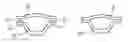
FIGS. 3A and 3B are end views of a structural assembly wherein at least one element of the assembly is formed from an SMC body and has a bonding section with a textured surface according to the present invention.
FIG. 4 is a perspective view of an SMC structural element.
FIG. 5 is a flowchart showing conventional processing of an SMC element prior to adhesive bonding.
FIG. 6 is a flowchart showing an improved method of the present invention for adhesively bonding an SMC element without conventional pre-treatment.
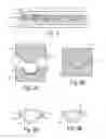
FIG. 7 is a perspective view of a portion of a compression mold according to one embodiment of the present invention.
FIG. 8 is a plan view of one embodiment of a textured surface according to one embodiment of the present invention.
FIG. 9 is a plan view of one embodiment of a textured surface according to another embodiment of the present invention.
FIG. 10 is a cross section through an adhesive bond joining an SMC element with a second element.
DETAILED DESCRIPTION OF PREFERRED EMBODIMENTS
Referring now to FIG. 1, an SMC body 10 is comprised of a resin paste 11 between a pair of films 12 and 13. A plurality of fibers 14 are embedded in resin paste 11.
An SMC body 20 may be inserted into a cavity in a compression molding tool having a lower portion 21 and an upper portion 22 configured to provide a mold cavity in the shape of a desired final SMC element. Lower tooling die 21 has bonding pad portions 23 and 24 and upper tooling die 22 has bonding pad sections 25 and 26, which are all conventionally given a smooth surface. Dies 21 and 22 are brought together to compress SMC body 20 while heat is applied in order to compression mold an SMC element 28 as shown in FIG. 2B.
As shown in FIGS. 3A and 3B, SMC element 28 has bonding sections 30 and 31 for bonding with a second element 32 in an automotive assembly. Bonding section 30 and 31 were conventionally pre-treated for better adherence of an adhesive 33 for joining elements 28 and 32 as shown in FIG. 3B.
FIG. 4 shows bonding sections 30 and 31 on SMC element 28 intended to receive the adhesive. Bonding surfaces 30 and 31 are compression molded and, therefore, had a smooth surface in the prior art due to a desire to provide a long lifetime for the compression molding die tools that interface with the SMC material. In order to deal with the abrasive tendencies of the SMC material, and due to the desire to obtain a smooth, blemish-free surface on all Class A portions of compression molded elements, all tooling surfaces have conventionally been polished smooth and then coated with chrome. Due to the smooth surfaces of bonding sections 30 and 31, pretreatment was necessary when using adhesive bonding.
One conventional prior art manufacturing method is shown in FIG. 5 wherein an SMC part is compression molded with a bonding pad in step 40. The bonding pad on the SMC part is then pre-treated in step 41 in order to roughen or activate the surface. In step 42, the SMC part and a second part to which it is being bonded are placed in a bonding fixture. Adhesive is applied in step 43, and the parts are compressed and the adhesive is allowed to cure in step 44. The surface treatment such as scuff sanding, flame treatment, and plasma treatment that have been routinely required to achieve acceptable bond performance were time consuming, labor intensive, and resulted in additional costs for the manufacturing of SMC components.
The present invention enhances SMC bonding by incorporating a textured tool surface for the bonding pads to obtain superior bonding adhesion without the need for pre-treatments. By deliberately introducing a predetermined surface roughness created by the mold at the bonding pad areas, an increased area of the bond surface is created which in turn provides increased joint strength. In one embodiment of a method of the present invention shown in FIG. 6, a texture is applied to a mold tooling die at the bonding pad surface in step 45. An SMC part is compression molded in step 46. In step 47, adhesive is applied to the bonding pad without pre-treatment. Thereafter, the parts to be bonded are compressed and the adhesive is cured in a conventional manner. The second component can be made of any desired material including a second SMC element with bonding pads similarly textured for ensuring excellent joint strength.
FIG. 7 shows a tooling die 51 having bonding pad portions 52 and 53 and a functional portion 54. Portions 52 and 53 have a predetermined surface roughness for increasing the effective surface area relative to a non-textured surface. Preferably, the predetermined surface roughness is in a range from 0.25 Ra (μm) to 8.5 Ra (μm). Textured surfaces 52 and 53 impress a corresponding texture into the SMC sheet body during compression molding so that the corresponding generally planar bonding sections on the SMC element are produced with the desired surface roughness, leading to enhanced joint strength when adhesively bonded.
Various textures can be employed to achieve the desired surface roughness. In one example, a multiplicity of lineal “scratches” is employed as shown in FIG. 8. Such scratches can be formed on the molding die by etching or machining to create a surface similar to what would result from scratching with sandpaper of various grits as reflected in the following table.
| Sample | Grit | Direction | Ra (μm) | |
| 1 | 400 | Parallel | 0.35 | |
| 2 | 400 | Transverse | 0.25 | |
| 3 | 240 | Parallel | 0.84 | |
| 4 | 240 | Transverse | 0.72 | |
| 5 | 120 | Parallel | 1.47 | |
| 6 | 120 | Transverse | 1.48 | |
| 7 | 80 | Parallel | 3.6 | |
| 8 | 80 | Transverse | 5.64 | |
Direction refers to whether the roughness measurement (e.g., using a profilometer) is taken in a direction parallel or transverse with the direction of the “scratches”. Samples 1 and 2 correspond to altering of the tooling surface in a manner equivalent to a 400 grit sandpaper in a direction parallel and transverse to the measurement direction, respectively. The resulting surface roughness for die samples 1 and 2 produce a value of Ra of 0.35 and 0.25, respectively. As known in the art, Ra is the arithmetic average of vertical deviations in a roughness profile.
In samples 3 and 4, a texture corresponding to a 240 grit sandpaper produces roughness Ra with values of 0.84 and 0.72, respectively. Altering the tooling surface equivalent to sandpaper grits of 120 and 80 result in the surface roughness as shown in the table. Using a texture that is coarser than 80 may be undesirable because the corresponding surface roughness would tend to expose internal fibers. A finer texture than 400 would be undesirable since insufficient surface roughness would be created and no significant increase in mechanical joint strength would be obtained. The most preferable range in predetermined surface roughness lies from about 0.35 Ra to about 3.6 Ra (μm).
FIG. 9 shows an alternative texture wherein any common stipple pattern with a grain exhibiting the desired surface roughness may be employed. Any stipple pattern could be selected provided that the roughness Ra of the stipple pattern falls in the range from 0.25 Ra (μm) to 8.5 Ra (μm).
FIG. 10 shows a first SMC element 55 and a second SMC element 56 with textured surfaces 57 and 58 having the predetermined surface roughness. An adhesive 60 has been applied and cured between textured surfaces 57 and 58. The respective surface areas of each SMC element that are in contact with adhesive 60 are increased relative to a non-textured surface to thereby increase joint strength. The surface texture is applied in a manner that avoids disruption of the internal fibers which could otherwise lead to delamination if fibers extended out from the SMC surface.
Claims
What is claimed is:1. A method of making an automotive assembly, comprising the steps of:
preparing a compression mold having a smooth functional portion and a bonding pad portion, wherein the compression mold has a textured surface defining the bonding pad portion, wherein the textured surface has a predetermined surface roughness for increasing the effective surface area of the bonding pad portion relative to a non-textured surface, wherein the predetermined surface roughness is in a range from 0.25 Ra (μm) to 8.5 Ra (μm), and wherein the smooth functional section has a respective surface roughness less than 0.25 Ra (μm);
inserting an SMC sheet body into the compression mold to shape the SMC sheet body into a generally smooth functional section within the functional portion of the compression mold and at least one generally planar bonding section within the bonding pad portion of the compression mold;
removing the shaped SMC sheet body from the compression mold;
aligning the bonding section with a second assembly element having a secondary bonding surface; and
bonding the bonding section and the secondary bonding surface with an adhesive.
2. The method of claim 1 wherein the textured surface has a textured pattern of generally parallel scratches.
3. The method of claim 1 wherein the second assembly element is made by the method further comprising the steps of:
preparing a second compression mold having a second functional portion and a second bonding pad portion, wherein the second compression mold has a second textured surface defining the second bonding pad portion, and wherein the second textured surface has a second predetermined surface roughness for increasing the effective surface area of the second bonding pad portion relative to a non-textured surface, wherein the second predetermined surface roughness is in a range from 0.25 Ra (μm) to 8.5 Ra (μm), and wherein the second functional portion has a respective surface roughness less than 0.25 Ra (μm);
inserting a second SMC sheet body into the second compression mold to shape the second SMC sheet body into a second generally smooth functional section within the second functional portion of the second compression mold and into the secondary bonding surface within the second bonding pad portion of the second compression mold.
4. The method of claim 3 wherein the second textured surface has a second textured pattern of generally parallel scratches.
Images & Drawings included:


Sources:
- United States Patent and Trademark Office - verify current appl. status at the USPTO↗
Similar patent applications:
Recent applications in this class:
- » 20250153479 2025-05-15
CURVED STRUCTUAL GLAZING COMPOSITE FORMED VIA COLD BENDING WITH IMPROVED DURABILITY - » 20250115041 2025-04-10
SYSTEMS AND METHODS FOR MANUFACTURING LARGE-SIZED SANDWICH PANEL - » 20240343030 2024-10-17
GUIDE FILM, METHOD OF FABRICATING THE GUIDE FILM, AND APPARATUS FOR AND METHOD OF FABRICATING DISPLAY DEVICE - » 20240075730 2024-03-07
METHODS TO MANUFACTURE A BUILDING PANEL WITH BEVEL - » 20230035906 2023-02-02
Guide film, method of fabricating the guide film, and apparatus for and method of fabricating display device - » 20220161540 2022-05-26
Stretch laminate - » 20220105719 2022-04-07
Methods of manufacturing optically anisotropic polymer thin films - » 20210379882 2021-12-09
MARKING TAPE, METHOD OF APPLYING AND METHOD OF MANUFACTURING THE MARKING TAPE - » 20210379881 2021-12-09
Guide film, method of fabricating the guide film, and apparatus for and method of fabricating display device - » 20210107270 2021-04-15
METHOD OF MANUFACTURING COMPOSITE MEMBER AND THE COMPOSITE MEMBER
Recent applications for this Assignee:
- » 20250293257 2025-09-18
LITHIUM-ION BATTERY COMPONENT WITH POLAR BINDER - » 20250289391 2025-09-18
MANIFOLD TO SELECTIVELY INFLATE SEAT AIRBAGS - » 20250289296 2025-09-18
SUN VISOR FOR A MOTOR VEHICLE - » 20250285043 2025-09-11
REFACTORING INPUT STRINGS - » 20250282426 2025-09-11
VEHICLE STRUCTURAL ASSEMBLY HAVING STRUT CAPS - » 20250282423 2025-09-11
STRUCTURAL ASSEMBLY HAVING POCKETS - » 20250282315 2025-09-11
RETRACTABLE BUMPER ASSEMBLY WITH LOCK - » 20250282220 2025-09-11
VEHICLE DISPLAY CONTROL - » 20250278084 2025-09-04
SYSTEMS AND METHODS FOR ENABLING VEHICLE MOVEMENT VIA FORCE APPLIED TO AN EXTERNAL INTERFACE - » 20250277401 2025-09-04
SYSTEMS AND METHODS FOR CONTROLLING VEHICLE COMPONENT OPERATION BASED ON USER DEVICE MOVEMENT PATTERN