Gas turbine
US20150192026A1
2015-07-09
14/584,811
2014-12-29
✅ Patent granted
US 9,416,676 B2
2016-08-16
-
-
Kristina Fulton | Eugene G Byrd
Barlow, Josephs & Holmes, Ltd.
2034-12-29
Abstract:
The present invention relates to a gas turbine having a housing (1), an outer sealing ring (2) that can be fastened detachably to the housing, a clamping member (3) for clamping the outer sealing ring and the housing together radially, and a rotation locking member that has at least one housing groove (10) and a radial flange (20) of the outer sealing ring that can be locked against rotation in the housing groove in form-fitting manner with play (sa) in the axial and/or peripheral direction.
Inventors:
- Rudolf Stanka 31 🇩🇪 Rattenkirchen, Germany
- Petra Kufner 13 🇩🇪 Poing, Germany
- Walter Gieg 10 🇩🇪 Eichenau, Germany
Assignee:
- MTU AERO ENGINES AG 486 🇩🇪 Munich, Germany
Applicant:
Interested in similar patents?
Get notified when new applications in this technology area are published.
Classification:
F01D11/005 » CPC main
Preventing or minimising internal leakage of working-fluid, e.g. between stages Sealing means between non relatively rotating elements
F01D11/00 IPC
Preventing or minimising internal leakage of working-fluid, e.g. between stages
F01D25/246 » CPC further
Component parts, details, or accessories, not provided for in, or of interest apart from, other groups; Casings ; Casing parts, e.g. diaphragms, casing fastenings Fastening of diaphragms or stator-rings
F01D11/08 » CPC further
Preventing or minimising internal leakage of working-fluid, e.g. between stages for sealing space between rotor blade tips and stator
F01D11/001 » CPC further
Preventing or minimising internal leakage of working-fluid, e.g. between stages for sealing space between stator blade and rotor
F01D25/24 IPC
Component parts, details, or accessories, not provided for in, or of interest apart from, other groups Casings ; Casing parts, e.g. diaphragms, casing fastenings
F01D25/285 » CPC further
Component parts, details, or accessories, not provided for in, or of interest apart from, other groups; Supporting or mounting arrangements, e.g. for turbine casing Temporary support structures, e.g. for testing, assembling, installing, repairing; Assembly methods using such structures
F01D11/127 » CPC further
Preventing or minimising internal leakage of working-fluid, e.g. between stages for sealing space between rotor blade tips and stator using a rubstrip, e.g. erodible. deformable or resiliently-biased part with a deformable or crushable structure, e.g. honeycomb
F05D2200/11 » CPC further
Mathematical features; Basic functions Sum
F05D2220/3212 » CPC further
Application in turbines in gas turbines for a special turbine stage the first stage of a turbine
F05D2230/60 » CPC further
Manufacture Assembly methods
F05D2230/68 » CPC further
Manufacture; Assembly methods using auxiliary equipment for lifting or holding
F05D2230/70 » CPC further
Manufacture Disassembly methods
F05D2240/11 » CPC further
Components; Stators Shroud seal segments
F05D2260/36 » CPC further
Function; Retaining components in desired mutual position by a form fit connection, e.g. by interlocking
F05D2260/37 » CPC further
Function; Retaining components in desired mutual position by a press fit connection
Y10T29/49233 » CPC further
Metal working; Method of mechanical manufacture; Prime mover or fluid pump making; I.C. [internal combustion] engine making Repairing, converting, servicing or salvaging
Y10T29/49318 » CPC further
Metal working; Method of mechanical manufacture; Impeller making Repairing or disassembling
Y10T29/49321 » CPC further
Metal working; Method of mechanical manufacture; Impeller making; Turbomachine making Assembling individual fluid flow interacting members, e.g., blades, vanes, buckets, on rotary support member
F01D5/20 IPC
Blades; Blade-carrying members ; Heating, heat-insulating, cooling or antivibration means on the blades or the members; Blades; Form or construction Specially-shaped blade tips to seal space between tips and stator
F01D11/12 » CPC further
Preventing or minimising internal leakage of working-fluid, e.g. between stages for sealing space between rotor blade tips and stator using a rubstrip, e.g. erodible. deformable or resiliently-biased part
F01D25/28 IPC
Component parts, details, or accessories, not provided for in, or of interest apart from, other groups Supporting or mounting arrangements, e.g. for turbine casing
B25B27/14 » CPC further
Hand tools, specially adapted for fitting together or separating parts or objects whether or not involving some deformation, not otherwise provided for for assembling objects other than by press fit or detaching same
Y10T29/53983 » CPC further
Metal working; Means to assemble or disassemble Work-supported apparatus
B23P15/04 » CPC further
Making specific metal objects by operations not covered by a single other subclass or a group in this subclass turbine or like blades from several pieces
Description
BACKGROUND OF THE INVENTION
The present invention relates to a gas turbine having a housing, an outer sealing ring that can be fastened detachably to the housing, and a clamping member for radially clamping together the outer sealing ring and the housing.
Known from US 2007/0231132 A1 is a gas turbine having a housing, an outer sealing ring that is fastened detachably to the housing, and a C-clip that clamps the outer sealing ring and the housing together radially. In this case, the outer sealing ring is fastened by friction fit in the peripheral direction.
In order to avoid vibration-induced micromovements between sealing ring and housing in the axial direction, the publication proposes arranging a radial flange of the sealing ring between the C-clip and the housing in an axially form-fitting manner. During operation, the C-clip is loaded by the force of gas in the direction of through-flow and thus clamps the radial flange of the sealing ring against the housing.
In the case of relative movements, particularly due to different thermal deformations, this clamping of sealing ring and housing exercises a high friction force that leads to a correspondingly high wear.
SUMMARY OF THE INVENTION
An object of an embodiment of the present invention is to provide an improved gas turbine.
The object is achieved by the gas turbine of the present invention. Advantageous embodiments of the invention are the subject of the present invention.
According to one aspect of the present invention, a gas turbine, particularly an aircraft-engine gas turbine, has a housing, an outer sealing ring that can be fastened, in particular is fastened, detachably to the housing, and a clamping member for clamping the outer sealing ring and the housing together radially, which in one embodiment clamps the outer sealing ring and the housing together radially and thus fastens them together by friction fit.
A rotation locking member or form-fit limitation of a relative movement between housing and outer sealing ring in the peripheral direction has one or more housing grooves that are distanced from one another in the peripheral direction, preferably equidistant, at least substantially, which in one embodiment extends, at least substantially in the axial direction. In the radial direction, the groove(s) can be open or closed radially outwardly, wherein radially outward open grooves can be advantageous with respect to manufacturing and/or assembly techniques; radially outward closed grooves, in contrast, can advantageously protect the rotation locking member.
In each case, one or more radial flanges of the outer sealing ring engage in one or more, preferably in all, housing grooves and thus secure (against rotation) housing and outer sealing ring in a in form-fitting manner in the peripheral direction. In this way, in one embodiment, a radial clamping or a friction fit between housing and outer sealing ring can be reduced and thus wear will also be reduced.
According to one aspect of the present invention, the radial flange or the radial flanges is (are) disposed in the housing groove or the housing grooves with play in the axial direction. In this way, in one embodiment, the high axial clamping force as a consequence of the gas force during operation as explained above, can be reduced and preferably avoided, and thus wear can be reduced.
Additionally or alternatively, the radial flange or the radial flanges can be disposed with play in the peripheral direction in the housing groove or housing grooves. In this way, in one embodiment, assembly can be simplified and/or manufacturing tolerances and/or thermal deformations can be compensated.
According to one aspect of the present invention, the housing groove(s) is (are) open on the front side against the direction of through-flow. In other words, the housing groove(s) discharge(s) into a front housing side in the direction of through-flow or open up into this side. In this case, in one embodiment, after removing the clamping member, the sealing ring advantageously can be pulled out from its mounted position from the front side of the housing or the housing, against the direction of through-flow, since, its radial flange(s) need not be removed from a closed groove counter to the direction of through-flow, for example, by initial tilting or tipping or the like.
In one embodiment, an axial length of the housing groove(s) from a front side of the housing is larger in the direction of through-flow than an axial wall thickness of the radial flange or the radial flanges. In this way, the above-described aspects of the open rotation locking member counter to the direction of through-flow are advantageously represented with axial play. An axial length in the present case is particularly understood as the length of a groove section in the axial direction, which extends in the direction of through-flow out from the opening in the front side of the housing and can receive the radial flange, thus in particular, a free path length of the radial flange in the direction of through-flow.
In one embodiment, the outer sealing ring is divided or segmented into two or more ring segments. In this way, advantageously, in one embodiment, the production, mounting and/or demounting can be improved.
In one embodiment, the clamping member is annular; in another embodiment, it is formed in ring segments. In particular, the clamping member can be designed in multiple parts and can have two or more ring segments distributed at equal distances over the circumference, in particular, at least substantially, whereby the sum of the circumferential lengths of the ring segments correspond to the circumferential length of the rotation locking member, but also, it is particularly clear that it can be smaller.
In particular, the clamping member can have one or more so-called C-clips. In general, the clamping member in one embodiment has a cross section having a C or U shape with a radially outer leg that is supported at an outer peripheral surface of the housing, and a radially inner leg that is supported at an inner peripheral surface of the outer sealing ring member, wherein the radially outer leg, the radial inner leg, and/or a combination of the two legs is (are) elastically deformed in order to thus clamp housing and outer sealing ring together radially.
In one embodiment, the gas turbine has a rotor that is disposed radially opposite the outer sealing ring member in the housing. The rotor, in particular, can be a frontmost first rotor closest to a gas inlet or in the direction of through-flow, and/or the outer sealing ring member can be a frontmost first outer sealing ring member closest to a gas inlet or in the direction of through-flow. If the gas turbine has a high-pressure turbine and a low-pressure turbine downstream to the latter in the direction of through-flow, the rotor or the outer sealing ring can be the first of either the high-pressure turbine or the low-pressure turbine. Correspondingly, the housing can be the housing of the high-pressure turbine or of the low-pressure turbine.
BRIEF DESCRIPTION OF THE DRAWING FIGURES
Additional advantageous enhancements of the present invention can be taken from the dependent claims and the following description of preferred embodiments. For this purpose and partially schematized, the following are shown:
FIG. 1 shows a portion of a gas turbine according to one embodiment of the present invention in an illustration corresponding to the prior art representation in FIG. 3;
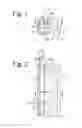
FIG. 2 shows a section along line II-II in FIG. 1; and
FIG. 3 shows a portion of a gas turbine according to the prior art in a meridian section.
DESCRIPTION OF THE INVENTION
FIG. 3 shows a portion of a gas turbine according to FIG. 2 of US 2007/0231132 A1; reference is made to the description thereof in its entirety, and the content thereof is included in the present disclosure.
The gas turbine of FIG. 3 has a housing 1′, to which an outer sealing ring 2′ having a honeycomb seal is attached. For this, a C-clip 3′ clamps an annular radial flange 20′ of the sealing ring axially against the housing in a form-fitting manner. During operation, the C-clip is loaded by the force of gas on a preceding guide vane 12 in the direction of through-flow and thus clamps the radial flange of the sealing ring against the housing.
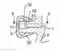
FIG. 1 shows a section along the line I-I in FIG. 2 of a portion of an aircraft-engine gas turbine according to an embodiment of the present invention in a representation corresponding to that in FIG. 3. FIG. 2 shows a section along line II-II in FIG. 1. Elements or members that correspond to one another are designated by the same reference numbers and distinguished by an apostrophe, as in prior art FIG. 3.
The gas turbine has a housing 1, an outer sealing ring 2, which is detachably fastened to the housing, and a clamping member 3, which radially (vertically in FIG. 1) clamps together the outer sealing ring and the housing and thus fastens them to one another in a friction fit.
Housing 1 and outer sealing ring 2 have a rotation locking member with several housing grooves 10 that are distanced from one another in the peripheral direction and that extend in the axial direction (horizontally in FIGS. 1, 2). The grooves are open radially outward (the top in FIG. 1) in the radial direction.
A radial flange 20 of the outer sealing ring 2 engages in each housing groove 10 of the housing 1 and thus secures housing and outer sealing ring in form-fitting manner in the peripheral direction (vertical in FIG. 2).
The radial flanges are disposed in the housing grooves with play sa in the axial direction. Additionally, the radial flanges also have play in the peripheral direction relative o the housing grooves, which can be recognized in FIG. 2.
The housing grooves are open on the front side counter to the direction of through-flow (toward the left in FIGS. 1, 2). In other words, the housing groove(s) discharge(s) into a front side of the housing 11 in the direction of through-flow. In this way, after removal of the clamping member 3, the sealing ring 2 advantageously can be pulled out from its mounting position shown in FIGS. 1, 2 from the front side of the housing 11 or the housing 1 axially counter to the direction of through-flow (toward the left in FIGS. 1, 2).
The axial length t1 of the housing grooves 10 from the front side of the housing 11 in the direction of through-flow is greater than the axial wall thickness t2 of the radial flange 20.
The outer sealing ring is divided or segmented into several ring segments (not shown).
The clamping member is formed in multiple parts shaped as ring segments and has several ring segments in the form of C-clips distributed over the circumference. Correspondingly, as can be seen in FIG. 1, the clamping member has a C-shaped cross section with a radially outer leg 31, which is supported at an outer peripheral surface of the housing 1, and a radially inner leg 32 that is supported at an inner peripheral surface of the outer sealing ring member 2, wherein the radially outer leg, the radial inner leg, and/or a combination of the two legs is (are) elastically deformed in order to thus clamp housing and outer sealing ring together radially.
The gas turbine has a first rotor 18 in the direction of through-flow (not shown in FIG. 1 but see FIG. 3).
Although exemplary embodiments have been explained in the preceding description, it shall be noted that a plurality of modifications is possible. In addition, it shall be noted that the exemplary embodiments only involve examples that in no way shall limit the scope of protection, the applications, and the structure. Rather, a guide is given to the person skilled in the art by the preceding description for implementing at least one exemplary embodiment, whereby diverse changes, particularly with respect to the function and arrangement of the described components, can be carried out without departing from the scope of protection, as results from the claims and combinations of features equivalent thereto.
Claims
What is claimed is:1. A gas turbine comprising a housing (1), an outer sealing ring (2) that can be detachably fastened to the housing, and a clamping member (3) for radially clamping the outer sealing ring and the housing together, further comprising a rotation locking member that has at least one housing groove (10) and a radial flange (20) of the outer sealing ring that is locked against rotation in the housing groove in form-fitting manner with play (sa) in the axial and/or peripheral direction.
2. The gas turbine according to claim 1, wherein the housing groove is open on the front side counter to the direction of through-flow.
3. The gas turbine according to claim 1, wherein an axial length (t1) of the housing groove from a front side of the housing (11) in the direction of through-flow is larger than an axial wall thickness (t2) of the radial flange.
4. The gas turbine according to claim 1, wherein the outer sealing ring is segmented.
5. The gas turbine according to claim 1, wherein the clamping member is annular or formed in ring segments.
6. The gas turbine according to claim 1, wherein the clamping member has a cross section that is C-shaped or U-shaped with two legs (31, 32), one of which (31) is supported at an outer peripheral surface of the housing, and the other (32) of which is supported at an inner circumferential surface of the outer sealing ring member with elastic deformation of the clamping ring member.
7. The gas turbine according to claim 1, further comprising a first rotor (18) in the direction of through-flow, the first rotor (18) being disposed in the housing opposite the outer sealing ring member.
Images & Drawings included:

Sources:
- United States Patent and Trademark Office - verify current appl. status at the USPTO↗
Similar patent applications:
- » 20070020102
Gas turbine blade or vane and platform element for a gas turbine blade or vane ring of a gas turbine, supporting structure for securing gas turbine blades or vanes arranged in a ring, gas turbine blade or vane ring and the use of a gas turbine blade or vane ring - » 20240191662
Control device for gas turbine, gas turbine facility, method for controlling gas turbine, and control program for gas turbine - » 20220042466
Device for controlling gas turbine, gas turbine facility, method for controlling gas turbine, and program for controlling gas turbine - » 20110250072
Replacement part for a gas turbine blade of a gas turbine, gas turbine blade and method for repairing a gas turbine blade - » 20240376825
FLOW BODY FOR A GAS TURBINE, GAS TURBINE, METHOD FOR MANUFACTURING A FLOW BODY FOR A GAS TURBINE, AND METHOD FOR REPAIRING A FLOW BODY OF A GAS TURBINE - » 20240376826
FLOW BODY FOR A GAS TURBINE, GAS TURBINE, METHOD FOR MANUFACTURING A FLOW BODY FOR A GAS TURBINE, AND METHOD FOR REPAIRING A FLOW BODY OF A GAS TURBINE - » 20240230471
ABNORMALITY DETECTION SYSTEM FOR COMBUSTOR FOR GAS TURBINE, COMBUSTOR FOR GAS TURBINE AND GAS TURBINE, AND ABNORMALITY DETECTION METHOD FOR COMBUSTOR FOR GAS TURBINE - » 20240133771
ABNORMALITY DETECTION SYSTEM FOR COMBUSTOR FOR GAS TURBINE, COMBUSTOR FOR GAS TURBINE AND GAS TURBINE, AND ABNORMALITY DETECTION METHOD FOR COMBUSTOR FOR GAS TURBINE - » 20130230392
Auxiliary member for assembly/disassembly of gas turbine casing, gas turbine having the same, assembly method of gas turbine casing, and disassembly method of gas turbine casing - » 20210172342
Gas turbine module, gas turbine plant including the same, method of unloading gas turbine module, and method of exchanging gas turbine module
Recent applications in this class:
- » 20250137384 2025-05-01
SEALING DEVICE AND FLOW MACHINE WITH THE SEALING DEVICE - » 20250116199 2025-04-10
SEAL FOR A GAS TURBINE ENGINE - » 20250003349 2025-01-02
ANNULAR SEAL WITH INTERLOCKED RINGS - » 20240368994 2024-11-07
Seal system using layers of seal segments forced into sealing engagement using tension cable - » 20240328324 2024-10-03
APPARATUS TO PREVENT AIR LEAKAGE IN TURBINE ENGINES - » 20240309771 2024-09-19
Seal assembly and a turbine with the same - » 20240247595 2024-07-25
Sealing system including a seal assembly between components - » 20240191632 2024-06-13
Turbine vane having sealing assembly, turbine, and turbomachine including same - » 20240191631 2024-06-13
Turbine vane platform sealing assembly, and turbine vane and gas turbine including same - » 20240011406 2024-01-11
Turbomachinery seal plate with variable lattice densities
Recent applications for this Assignee:
- » 20240318578 2024-09-26
TURBOMACHINE FOR AN AIRCRAFT PROPULSION DRIVE - » 20240240564 2024-07-18
Blisk - » 20240091861 2024-03-21
METHOD FOR AVOIDING RESONANCE DAMAGE DURING CLEANING OF AN AT LEAST PARTLY ADDITIVELY MANUFACTURED COMPONENT, CLEANING DEVICE, MASS ELEMENT, AND SYSTEM - » 20240058901 2024-02-22
Braze alloy mix for application in a method for brazing a component, additive alloy, brazing method, and component - » 20240018874 2024-01-18
Rotor blade and rotor blade assembly for a turbomachine - » 20240003353 2024-01-04
Compressor for an engine - » 20230392513 2023-12-07
Guide vane device, mounting tool, as well as turbomachine and method for mounting and dismantling the guide vane device - » 20230340884 2023-10-26
BLADE FOR A TURBOMACHINE INCLUDING BLADE TIP ARMOR AND AN EROSION PROTECTION LAYER, AND METHOD FOR MANUFACTURING SAME - » 20230332522 2023-10-19
Exhaust-gas treatment device for an aircraft engine - » 20230332505 2023-10-19
Guide vane ring and rotor blade ring for a turbofan engine