Device for assembly of ball heads and adapter sleeves as integrated component part of the package
US20150209148A1
2015-07-30
14/677,635
2015-04-02
✅ Patent granted
US 9,717,596 B2
2017-08-01
-
-
Andrew Perreault
Norton Rose Fulbright US LLP
2035-04-02
Abstract:
A package for receiving an adapter sleeve for a hip endoprosthesis, the hip endoprosthesis comprising a ball head which has to be pushed onto the adapter sleeve with a defined pushing-on force. For simplification and secure fastening of the ball head on the adapter sleeve, it is proposed according to the invention that a device for the mounting of the ball head on the adapter sleeve is integrated in the package and this device comprises indicating elements which indicate that the defined pushing-on force has been reached when the ball head is pressed onto the adapter sleeve. Preferably the package has indicating elements.
Inventors:
- Heinrich Wecker 21 🇩🇪 Eckental, Germany
- Martin DIETRICH 5 🇩🇪 Potenitz, Germany
- Patricie MERKERT 5 🇩🇪 Kirchheim u. Teck, Germany
- Roman PREUSS 7 🇩🇪 Leinf.-Echterdingen, Germany
- Paul SILBERER 3 🇩🇪 Waghausel, Germany
Assignee:
- CERAMTEC GMBH 88 🇩🇪 Plochingen, Germany
Applicant:
Interested in similar patents?
Get notified when new applications in this technology area are published.
Classification:
A61F2/32 » CPC further
Filters implantable into blood vessels; Prostheses, i.e. artificial substitutes or replacements for parts of the body; Appliances for connecting them with the body; Devices providing patency to, or preventing collapsing of, tubular structures of the body, e.g. stents; Prostheses implantable into the body; Joints for the hip
A61F2/34 » CPC main
Filters implantable into blood vessels; Prostheses, i.e. artificial substitutes or replacements for parts of the body; Appliances for connecting them with the body; Devices providing patency to, or preventing collapsing of, tubular structures of the body, e.g. stents; Prostheses implantable into the body; Joints for the hip Acetabular cups
A61F2/3609 » CPC further
Filters implantable into blood vessels; Prostheses, i.e. artificial substitutes or replacements for parts of the body; Appliances for connecting them with the body; Devices providing patency to, or preventing collapsing of, tubular structures of the body, e.g. stents; Prostheses implantable into the body; Joints for the hip; Femoral heads ; Femoral endoprostheses Femoral heads or necks; Connections of endoprosthetic heads or necks to endoprosthetic femoral shafts
A61F2220/0025 » CPC further
Fixations or connections for prostheses classified in groups - or or or or subgroups thereof Connections or couplings between prosthetic parts, e.g. between modular parts; Connecting elements
A61B50/30 » CPC further
Containers, covers, furniture or holders specially adapted for surgical or diagnostic appliances or instruments, e.g. sterile covers Containers specially adapted for packaging, protecting, dispensing, collecting or disposing of surgical or diagnostic appliances or instruments
A61F2/0095 » CPC further
Filters implantable into blood vessels; Prostheses, i.e. artificial substitutes or replacements for parts of the body; Appliances for connecting them with the body; Devices providing patency to, or preventing collapsing of, tubular structures of the body, e.g. stents Packages or dispensers for prostheses or other implants
A61F2/30721 » CPC further
Filters implantable into blood vessels; Prostheses, i.e. artificial substitutes or replacements for parts of the body; Appliances for connecting them with the body; Devices providing patency to, or preventing collapsing of, tubular structures of the body, e.g. stents; Prostheses implantable into the body; Joints Accessories
A61F2/4637 » CPC further
Filters implantable into blood vessels; Prostheses, i.e. artificial substitutes or replacements for parts of the body; Appliances for connecting them with the body; Devices providing patency to, or preventing collapsing of, tubular structures of the body, e.g. stents; Prostheses implantable into the body; Joints; Special tools or methods for implanting or extracting artificial joints, accessories, bone grafts or substitutes, or particular adaptations therefor for connecting or disconnecting two parts of a prosthesis
B65D25/101 » CPC further
Details of other kinds or types of rigid or semi-rigid containers; Internal fittings; Devices to locate articles in containers Springs, elastic lips, or other resilient elements to locate the articles by pressure
A61B2050/314 » CPC further
Containers, covers, furniture or holders specially adapted for surgical or diagnostic appliances or instruments, e.g. sterile covers; Containers specially adapted for packaging, protecting, dispensing, collecting or disposing of surgical or diagnostic appliances or instruments Flexible bags or pouches
A61F2002/30474 » CPC further
Filters implantable into blood vessels; Prostheses, i.e. artificial substitutes or replacements for parts of the body; Appliances for connecting them with the body; Devices providing patency to, or preventing collapsing of, tubular structures of the body, e.g. stents; Prostheses implantable into the body; Joints; Additional features of subject-matter classified in , and subgroups thereof; The prosthesis having different structural features at different locations within the same prosthesis; Connections between prosthetic parts; Special structural features of bone or joint prostheses not otherwise provided for; Connections or couplings between prosthetic parts, e.g. between modular parts; Connecting elements using an intermediate sleeve interposed between both prosthetic parts to be coupled
A61F2002/30558 » CPC further
Filters implantable into blood vessels; Prostheses, i.e. artificial substitutes or replacements for parts of the body; Appliances for connecting them with the body; Devices providing patency to, or preventing collapsing of, tubular structures of the body, e.g. stents; Prostheses implantable into the body; Joints; Additional features of subject-matter classified in , and subgroups thereof; The prosthesis having different structural features at different locations within the same prosthesis; Connections between prosthetic parts; Special structural features of bone or joint prostheses not otherwise provided for; Special structural features of bone or joint prostheses not otherwise provided for Force-limiting means
A61F2002/365 » CPC further
Filters implantable into blood vessels; Prostheses, i.e. artificial substitutes or replacements for parts of the body; Appliances for connecting them with the body; Devices providing patency to, or preventing collapsing of, tubular structures of the body, e.g. stents; Prostheses implantable into the body; Joints for the hip; Femoral heads ; Femoral endoprostheses; Femoral heads or necks; Connections of endoprosthetic heads or necks to endoprosthetic femoral shafts Connections of heads to necks
A61F2002/3611 » CPC further
Filters implantable into blood vessels; Prostheses, i.e. artificial substitutes or replacements for parts of the body; Appliances for connecting them with the body; Devices providing patency to, or preventing collapsing of, tubular structures of the body, e.g. stents; Prostheses implantable into the body; Joints for the hip; Femoral heads ; Femoral endoprostheses; Femoral heads or necks; Connections of endoprosthetic heads or necks to endoprosthetic femoral shafts Heads or epiphyseal parts of femur
A61F2002/4666 » CPC further
Filters implantable into blood vessels; Prostheses, i.e. artificial substitutes or replacements for parts of the body; Appliances for connecting them with the body; Devices providing patency to, or preventing collapsing of, tubular structures of the body, e.g. stents; Prostheses implantable into the body; Joints; Special tools or methods for implanting or extracting artificial joints, accessories, bone grafts or substitutes, or particular adaptations therefor; Measuring instruments used for implanting artificial joints for measuring force, pressure or mechanical tension
A61F2002/4689 » CPC further
Filters implantable into blood vessels; Prostheses, i.e. artificial substitutes or replacements for parts of the body; Appliances for connecting them with the body; Devices providing patency to, or preventing collapsing of, tubular structures of the body, e.g. stents; Prostheses implantable into the body; Joints; Special tools or methods for implanting or extracting artificial joints, accessories, bone grafts or substitutes, or particular adaptations therefor having operating or control means acoustic
A61F2220/0033 » CPC further
Fixations or connections for prostheses classified in groups - or or or or subgroups thereof; Connections or couplings between prosthetic parts, e.g. between modular parts; Connecting elements made by longitudinally pushing a protrusion into a complementary-shaped recess, e.g. held by friction fit
A61F2230/0067 » CPC further
Geometry of prostheses classified in groups - or or or or subgroups thereof; Three-dimensional shapes conical
A61F2250/0073 » CPC further
Special features of prostheses classified in groups - or or or or subgroups thereof; Additional features; Implant or prostheses properties not otherwise provided for Force-limiting means
A61F2/36 IPC
Filters implantable into blood vessels; Prostheses, i.e. artificial substitutes or replacements for parts of the body; Appliances for connecting them with the body; Devices providing patency to, or preventing collapsing of, tubular structures of the body, e.g. stents; Prostheses implantable into the body; Joints for the hip Femoral heads ; Femoral endoprostheses
A61F2/46 IPC
Filters implantable into blood vessels; Prostheses, i.e. artificial substitutes or replacements for parts of the body; Appliances for connecting them with the body; Devices providing patency to, or preventing collapsing of, tubular structures of the body, e.g. stents; Prostheses implantable into the body; Joints Special tools or methods for implanting or extracting artificial joints, accessories, bone grafts or substitutes, or particular adaptations therefor
B65D25/10 IPC
Details of other kinds or types of rigid or semi-rigid containers; Internal fittings Devices to locate articles in containers
A61F2/00 IPC
Filters implantable into blood vessels; Prostheses, i.e. artificial substitutes or replacements for parts of the body; Appliances for connecting them with the body; Devices providing patency to, or preventing collapsing of, tubular structures of the body, e.g. stents
A61F2/30 IPC
Filters implantable into blood vessels; Prostheses, i.e. artificial substitutes or replacements for parts of the body; Appliances for connecting them with the body; Devices providing patency to, or preventing collapsing of, tubular structures of the body, e.g. stents; Prostheses implantable into the body Joints
Description
The invention relates to a package for receiving an adapter sleeve for a hip endoprosthesis, the hip endoprosthesis comprising a ball head which has to be pushed onto the adapter sleeve with a defined pushing-on force.
On the market there are various modular systems for hip endoprostheses in which the ball head is seated on an adapter sleeve and the latter in turn is seated on the prosthesis cone. The components in these systems are generally ones which are connected to one another via conical clamping connections. Furthermore, all the parts are generally delivered separately and not preassembled, in order to avoid changes of the plug connections owing to external influences during transportation.
Three problems arise here.
- 1. it must be clear to the user performing the assembly of the components in what order the assembly is to be carried out.
- 2. It must be clear to the user, particularly in the case of conical plug connections, with what initial force the components are to be joined.
- 3. The plug connection of the ball head and adapter sleeve must be clean. There must be no dirt particles present on the contact surface.
The present invention offers a solution to all three problems:
According to the invention, a device for the mounting of the ball head on the adapter sleeve is integrated in the package and this device comprises indicating elements which indicate that the defined pushing-on force has been reached when the ball head is pressed onto the adapter sleeve. As a result, the assembly is simplified and the user can tell whether he has pushed the ball head onto the adapter sleeve with the necessary pushing-on force.
In one embodiment according to the invention, the device for the mounting comprises a projection of the package, which projection can be pressed in as far as a stop and on which the adapter sleeve is placed, and the stop indicates that the necessary pushing-on force has been reached when the ball head is pressed onto the adapter sleeve.
The material and/or the configuration of the projection which can be pressed in is chosen so that the projection touches the stop only when the necessary pushing-on force has been reached. The stop may also be the bottom of the package.
Preferably, the projection is designed so that it can buckle in the region of the front end of the adapter sleeve.
In another embodiment, the device for the mounting of the ball head on the adapter sleeve is designed as a yielding, collapsible structure and the collapsing of the structure indicates that the necessary pushing-on force has been reached when the ball head is pressed onto the adapter sleeve.
Preferably, the structure is designed so that it produces a sound, such as, for example, a click, when it collapses.
In an advantageous configuration, a package anti-abrasion disc is arranged between the adapter sleeve and the projection or the package, so that the adapter sleeve does not touch the projection and/or the package. As a result, no abrasion of material from the package occurs, which could be deposited on the adapter sleeve or the ball head and lead to problems during the implantation.
In one embodiment according to the invention, the package anti-abrasion disc is designed as an air cushion which bursts when the force with which the ball head is being pushed onto the adapter sleeve is large enough. The bursting indicates to the user that the pushing-on force is large enough.
In another embodiment of the invention, the package anti-abrasion disc is designed as a spatial structure deformable through the effect of force, the structure comprising means which are spaced from one another and touch only when the force with which the ball head is being pushed onto the adapter sleeve is large enough.
Advantageously, the means are laminas which are separated from one another by a spacer.
In one embodiment of the invention, a chemical reaction with a change of colour is triggered by the materials or coating of the means or the laminas when they touch. As a result, the user can tell when the pushing-on force is large enough.
In an alternative embodiment according to the invention, a piezoelectric element which measures and indicates the pushing-on force or initiates the indication is arranged between the adapter sleeve and the package, optionally in addition to the package anti-abrasion disc, it being possible for the indicating element to be, for example, a lamp or a sound generator.
In another embodiment of the invention, the projection is designed as a conical peg on which a package anti-abrasion disc is arranged in a manner displaceable in the longitudinal direction of the peg on pressure application, and the adapter sleeve when encompassing the peg sits on the package anti-abrasion disc and displaces the package anti-abrasion disc when the ball head is pressed onto the adapter sleeve.
Advantageously, the point up to which the package anti-abrasion disc has to be displaced when pressure is being applied to the adapter sleeve by the ball head is marked or is a stop, such as, for example, the bottom of the package.
Advantageously, a ball head is also removably positioned in the package at the same time, and the ball head can be removed separately.
The invention is thus distinguished by the fact that the ball head and the adapter sleeve are positioned in a package such that the ball head can be removed separately. The adapter sleeve remains in the package and the ball head is then pushed directly onto the adapter sleeve still situated in the package. Furthermore, there is integrated in the package a device which delivers feedback to the user when the necessary pushing-on force has been reached when the ball head is pressed onto the adapter sleeve. The feedback here may, for example, be tactile or by visual or audio signals.
The invention is explained in more detail below with the aid of various figures.
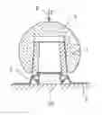
FIG. 1 shows in cross-section an adapter sleeve 1, which is seated in a raised manner on a cylindrical projection 2 of a package 3. This is the state in which the package 3 is delivered. What is not shown is that, in addition to the adapter sleeve 1, a ball head is also removably arranged in the package 3 in any way. In order that the adapter sleeve 1 does not move on the projection 2, a cylinder 18, the diameter of which corresponds to the inside diameter of the adapter sleeve 1 at the front end, is arranged on the projection 2.
FIG. 2 shows the package 3 according to FIG. 1 shortly after use. The ball head a has been placed on the adapter sleeve 1. With increasing pressure of the ball head 4 on the adapter sleeve 1, the cylindrical projection 2 gives way until the base of the package 3 is reached. The base acts as a mechanical stop so to speak and signals that a sufficient force has been applied (tactile feedback). The material or the configuration of the cylindrical projection 2 must be chosen so that the latter touches the base of the package 3 only when the ball head 4 is pressed onto the adapter sleeve 1 with sufficient pressure.
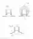
FIG. 3 shows an embodiment in which the projection of the package 3 is designed as a yielding, collapsible structure 5, so that when the necessary force is reached the structure 5 collapses and a click can be heard (tactile and audio feedback). The reference symbol 5a denotes the structure in the non-collapsed state, i.e. in the starting state. The broken line 5b shows the structure in the collapsed state, i.e. that the force applied has been sufficient.
The force applied by the ball head is indicated in this figure and also the following figures by the arrow 6.
FIG. 4 shows a projection of the package 3 which is designed as a conical peg 7, with the adapter sleeve 1 being pushed onto this peg 7. Located under the adapter sleeve 1 on the peg 7 of the projection is a package anti-abrasion disc 14, which is intended to prevent the adapter sleeve 1 and the package 3 from touching. As a result, no abrasion of material from the package 3 occurs, which could be deposited on the adapter sleeve 1 or the ball head and lead to problems during the implantation.
When the package anti-abrasion disc 14 remains displaced in a defined manner on the conical peg 7 after the ball head has been pressed onto the adapter sleeve 1, then the pushing-on force has been sufficient. The point up to which the package anti-abrasion disc 14 has to be displaced for the pushing-on force to be sufficient is advantageously marked or is the bottom of the package 3.
FIG. 5 shows the package according to FIG. 4 in the displaced state of the package anti-abrasion disc 14. The arrow 9 indicates the lifting-off of the ball head, which is now firmly connected to the adapter sleeve 1, from the peg 7. The ball head is not shown here.
FIG. 6 shows an embodiment in which the package anti-abrasion disc is designed as an air cushion 10 which bursts when the ball head is pressed with sufficient force onto the adapter sleeve 1. This is shown in FIG. 7. The projection 11 is preferably of cylindrical form in this embodiment and corresponds to the cylinder 18 of FIG. 1.
FIG. 8 shows a package anti-abrasion disc 14 which is composed of two laminas 12 separated by a spacer 13. When sufficient pressure is exerted on the adapter sleeve 1 by the ball head, at least one of the laminas 12 in the package anti-abrasion disc 14 is deformed to such a degree that it touches the other lamina 12. This could be indicated in various ways. Preferably, a chemical reaction with a change of colour could be triggered by the materials or coatings of the laminas 12. The broken line 12a denotes the lamina which has been bent through the effect of force and is touching the other lamina 12b.
FIG. 9 shows an embodiment in which a sufficient pressure of the ball head on the adapter sleeve 1 or on the package anti-abrasion disc is measured and indicated electronically/electrically, for example, by piezoelectric elements 15 and feedback to a signal generator 16. The signal generator 16 could, for example, be a lamp or a sound generator.
Claims
1-15. (canceled)
16. A package for receiving an adapter sleeve for a hip endoprosthesis, the hip endoprosthesis comprising a ball head which has to be pushed onto the adapter sleeve with a defined pushing-on force, wherein a device for mounting of the ball head on the adapter sleeve is integrated in the package, said device comprising indicating elements which indicate that the defined pushing-on force has been reached when the ball head is pressed onto the adapter sleeve.
17. A package according to claim 16, wherein the device for mounting further comprises a projection of the package which can be pressed in as far as a stop and on which the adapter sleeve is placed, and the stop indicates that the necessary pushing-on force has been reached when the ball head is pressed onto the adapter sleeve.
18. A package according to claim 17, wherein at least one of a material or a configuration of the projection which can be pressed in is selected such that the projection touches the stop only when the necessary pushing-on force has been reached.
19. A package according to claim 16, wherein the projection is designed so that it can buckle in the region of the front end of the adapter sleeve.
20. A package according to claim 15, wherein the device for the mounting of the ball head on the adapter sleeve is designed as a yielding, collapsible structure and the collapsing of the structure indicates that the necessary pushing-on force has been reached when the ball head is pressed onto the adapter sleeve.
21. A package according to claim 20, wherein the structure is designed so that it produces a sound when it collapses.
22. A package according to one of the preceding claims, wherein a package anti-abrasion disc is arranged between the adapter sleeve and the projection or the package such that the adapter sleeve does not touch at least one of the projection or the package.
23. A package according to claim 22, wherein the package anti-abrasion disc is designed as an air cushion which bursts when the force with which the ball head is pushed onto the adapter sleeve is large enough.
24. A package according to claim 22, wherein the package anti-abrasion disc is designed as a spatial structure deformable through the effect of force, the structure comprising means which are spaced from one another and touch only when the force with which the ball head is pushed onto the adapter sleeve is large enough.
25. A package according to claim 24, wherein the means are laminas which are separated from one another by a spacer.
26. A package according to claim 23, wherein a chemical reaction with a change of color is triggered by the materials or coating of the means or the laminas when they touch.
27. A package according to claim 15, further comprising a piezoelectric element which measures and indicates the pushing-on force is arranged between the adapter sleeve and the package.
28. A package according to claim 15, wherein the projection is designed as a conical peg on which a package anti-abrasion disc is arranged in a manner displaceable in the longitudinal direction of the peg on pressure application, and the adapter sleeve when encompassing the peg sits on the package anti-abrasion disc and displaces the package anti-abrasion disc when the ball head is pressed onto the adapter sleeve.
29. A package according to claim 15, wherein the point up to which the package anti-abrasion disc has to be displaced when pressure is applied to the adapter sleeve by the ball head is marked or is a stop.
30. A package according to claim 15, wherein a ball head is also removably positioned in the package at the same time, and wherein the ball head can be removed separately.
Images & Drawings included:


Sources:
- United States Patent and Trademark Office - verify current appl. status at the USPTO↗
Similar patent applications:
Recent applications in this class:
- » 20250195232 2025-06-19
RESURFACING CUP FOR ACETABULUM HEMIARTHROPLASTY OF THE HIP JOINT - » 20250195231 2025-06-19
IMPLANT COMPONENTS AND METHODS - » 20250152367 2025-05-15
HIP JOINT DEVICE AND METHOD - » 20250143886 2025-05-08
Cemented Sheath For Joint Implant - » 20250120817 2025-04-17
ARTIFICIAL HIP JOINT - » 20250090331 2025-03-20
ACETABULAR CUP AND HIP JOINT PROSTHESIS ASSEMBLY - » 20250082475 2025-03-13
DUAL MOBILITY ACETABULAR COMPONENT - » 20250032263 2025-01-30
ARTIFICIAL ACETABULAR CUP AND MANUFACTURING METHOD THEREOF - » 20250017736 2025-01-16
APPARATUS AND METHOD FOR INSTALLING AN ACETABULAR LINER ON AN ACETABULAR CUP - » 20250017735 2025-01-16
NON-IMPINGING DUAL MOBILITY HIP PROSTHESIS
Recent applications for this Assignee:
- » 20210384115 2021-12-09
Module with connection lugs for supply lines - » 20210071697 2021-03-11
Connection arrangement of two components - » 20200030888 2020-01-30
Tool system - » 20190366444 2019-12-05
Tool system - » 20190091031 2019-03-28
Knee endoprosthesis for replacing at least parts of the knee joint - » 20190006578 2019-01-03
Production of lead-free piezoceramics in aqueous surroundings - » 20190001419 2019-01-03
Carrier tool, cutting insert, and clamping element - » 20170362131 2017-12-21
α/β-sialon having improved sintering activity and high edge strength - » 20170348464 2017-12-07
COMPONENTS FOR FUSING VERTEBRAL BODIES - » 20170341154 2017-11-30
Cutting insert geometry