Turbine wheel
US20150211374A1
2015-07-30
14/425,660
2013-09-11
✅ Patent granted
US 9,915,152 B2
2018-03-13
WO; PCT/US2013/059159; 20130911
WO; WO2014/046927; 20140327
Logan Kraft | Jason Fountain
Eric L. Doyle | Stephan A. Pendorf | Patent Central LLC
2034-05-30
Abstract:
A turbine wheel (4) having a hub (29); a multiplicity of turbine wheel blades (30) arranged around the hub (29); a turbine wheel back wall (31) which is arranged on the hub (29) adjacent to an edge region (32) of the turbine wheel blades (30); wherein the wall thickness (W) of the turbine wheel (4) back wall is reduced in regions.
Assignee:
- BORGWARNER INC. 1,827 🇺🇸 Auburn Hills, MI, United States
Applicant:
Interested in similar patents?
Get notified when new applications in this technology area are published.
Classification:
F01D5/225 » CPC main
Blades; Blade-carrying members ; Heating, heat-insulating, cooling or antivibration means on the blades or the members; Blades; Blade-to-blade connections, e.g. for damping vibrations by shrouding
F01D5/048 » CPC further
Blades; Blade-carrying members ; Heating, heat-insulating, cooling or antivibration means on the blades or the members; Blade-carrying members, e.g. rotors for radial-flow machines or engines of the axial inlet- radial outlet, or , type Form or construction
F05D2220/40 » CPC further
Application in turbochargers
F01D5/22 IPC
Blades; Blade-carrying members ; Heating, heat-insulating, cooling or antivibration means on the blades or the members; Blades Blade-to-blade connections, e.g. for damping vibrations
F01D5/04 IPC
Blades; Blade-carrying members ; Heating, heat-insulating, cooling or antivibration means on the blades or the members; Blade-carrying members, e.g. rotors for radial-flow machines or engines
F05D2250/29 » CPC further
Geometry; Three-dimensional machined; miscellaneous
F05D2260/96 » CPC further
Function Preventing, counteracting or reducing vibration or noise
F04D29/32 IPC
Details, component parts, or accessories; Rotors specially for elastic fluids for axial flow pumps
F02B37/00 » CPC further
Engines characterised by provision of pumps driven at least for part of the time by exhaust
Description
The invention relates to a turbine wheel as per the preamble of claim 1 and to an exhaust-gas turbocharger as per the preamble of claim 5.
A known turbine wheel has a hub around which a multiplicity of turbine wheel blades are arranged. A turbine wheel back wall is arranged on the hub at an edge region, which in the installed state of the turbine wheel is adjacent to a shaft, of the turbine wheel blades.
It is an object of the present invention to provide a turbine wheel of the type specified in the preamble of claim 1, the mass moment of inertia of which turbine wheel is reduced.
This object is achieved by the features of claim 1.
It is accordingly possible according to invention for the wall thickness of the turbine wheel back wall to be reduced at least in regions.
The dependent claims contain advantageous developments of the inventions.
For the reduction of the wall thickness of the turbine wheel back wall in regions, said turbine wheel back wall may preferably be provided with pockets which are open on one side and which are arranged on that side of the turbine wheel back wall which faces away from the turbine wheel blades.
Said pockets are preferably arranged on the outer diameter of the turbine wheel, between the turbine wheel blades.
The depth of the pockets is dependent on the desired extent of the reduction in mass moment of inertia. In any case, however, the pockets are not formed so as to be continuous, that is to say are not formed so as to extend through the entire wall thickness of the turbine wheel back wall.
The arrangement at the outer diameter or outer circumference of the turbine wheel means that the pockets are arranged at the inlet diameter or inlet circumference of the turbine wheel.
The exhaust-gas turbocharger according to invention defined in claim 5 is provided with a turbine wheel according to the invention.
Further details, advantages and features of the present invention become apparent from the following description of exemplary embodiments with reference to the drawing, in which:
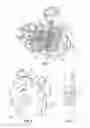
FIG. 1 shows a perspective sectional illustration through an exhaust-gas turbocharger according to the invention,
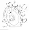
FIG. 2 shows a perspective illustration of a turbine wheel according to the invention, and
FIG. 3 shows a sectional illustration through a partial region of the turbine wheel as per FIG. 2.
FIG. 1 illustrates an exhaust-gas turbocharger 1 according to the invention which has a turbine housing 2 in which a turbine wheel 4 is arranged.
With regard to all other components of the exhaust-gas turbocharger 1 according to the invention, reference may be made to the list of reference signs provided at the end of this description, because a detailed description of said elements is not important for explaining the principles of the present invention.
The turbine wheel 4 according the invention is illustrated in FIG. 2. Said turbine wheel 4 has a hub 29 around which are arranged a multiplicity of turbine wheel blades, of which, in FIG. 2, one turbine wheel blade is identified, representatively of all of the blades, by the reference sign 30.
The turbine wheel 4 furthermore has a turbine wheel back wall 31 which is arranged on the hub 29 at an edge region 32 of the turbine wheel blades 30. As shown by FIG. 2 in conjunction with FIG. 1, the edge region 32 is that region which, in the installed state of the turbine wheel 4, faces toward a shaft 34, to which shaft the turbine wheel 4 is fastened, of the exhaust-gas turbocharger 1.
As can be seen viewing FIGS. 2 and 3 together, for the reduction of the wall thickness W of the turbine wheel back wall 31 in regions, it is provided in the example that a multiplicity of pockets which are open on one side are arranged in the turbine wheel back wall 31, of which pockets one pocket 33 is denoted, representatively of all of the pockets, in FIGS. 2 and 3. The pockets 33 may be of various forms, for example semi-circular, and do not extend through the entire wall thickness W, as can be seen from the reduced wall thickness WR, indicated in FIG. 3, in the region of the pockets 33.
The pockets 33 are furthermore arranged at the outer circumference (inlet circumference) 35 of the turbine wheel 4 or of the turbine wheel back wall 31.
The number of pockets 33, and also the depth thereof in the wall thickness W of the turbine wheel back wall 31, may be reduced or increased depending on the application.
In addition to the above written disclosure of the invention, reference is hereby explicitly made to the illustrative presentation of the invention in FIGS. 1 to 3.
LIST OF REFERENCE SIGNS
1 Turbocharger
2 Turbine housing
3 Compressor housing
4 Turbine wheel
5 Unison ring
6 Blade bearing ring
7 Adjusting blades
8 Rotary axles
9 Supply duct
10 Axial connector
11 Actuating device
12 Control casing
13 Free space for adjusting blades 7
14 Plunger element
15 Annular part of the turbine housing 2
16 Spacer/spacer cam
17 Compressor wheel
18 Guide grate
28 Bearing housing
29 Hub
30 Turbine wheel blades
31 Turbine wheel back wall
32 Edge
33 Pockets
34 Shaft
W Wall thickness of the turbine wheel back wall
WR Reduced wall thickness
R Axis of rotation
Claims
1. A turbine wheel (4) having
a hub (29) including a radially enlarged disc-like portion of the hub, the disk-like portion defining a floor on one side and a back wall (31) on the other side; and
a multiplicity of turbine wheel blades (30) arranged around the hub (29);
wherein
the wall thickness (W) of the radially enlarged disc-like portion of the hub is reduced in regions adjacent to an edge region (32) of the turbine wheel.
2. The turbine wheel as claimed in claim 1, wherein the turbine wheel back wall (31) has at least one pocket (33) which is open on one side.
3. The turbine wheel as claimed in claim 2, wherein the pocket or the pockets (33) are arranged on the inlet circumference (35) of the turbine wheel back wall (31).
4. The turbine wheel as claimed in claim 2, wherein the pocket or the pockets (33) do not extend through the entire wall thickness (W) of the turbine wheel back wall (31).
5. An exhaust-gas turbocharger (1)
having a turbine housing (2) in which is arranged a turbine wheel (4) which has:
a hub (29);
a multiplicity of turbine wheel blades (30) arranged around the hub (29), and
a turbine wheel back wall (31) which is arranged on the hub (29) adjacent to an edge region (32) of the turbine wheel blades (30),
wherein
the wall thickness (W) of the turbine wheel back wall (31) is reduced in regions.
6. The exhaust-gas turbocharger as claimed in claim 5, wherein the turbine wheel back wall (31) has at least one pocket (33) which is open on one side.
7. The exhaust-gas turbocharger as claimed in claim 5, wherein the pocket or the pockets (33) are arranged on the circumference (35) of the turbine wheel back wall (31).
8. The exhaust-gas turbocharger as claimed in claim 5, wherein the pocket or the pockets (33) do not extend through the entire wall thickness (W) of the turbine wheel back wall (31).
Images & Drawings included:
Sources:
- United States Patent and Trademark Office - verify current appl. status at the USPTO↗
Similar patent applications:
- » 20100203472
Turbine wheel for a gas operated medical handpiece and medical handpiece having a turbine wheel, and method for milling a blade of a turbine wheel - » 20180156054
Turbine wheels, turbine engines including the same, and methods of forming turbine wheels with improved seal plate sealing - » 20200353577
TURBINE WHEELS, TURBINE ENGINES INCLUDING THE SAME, AND METHODS OF FABRICATING TURBINE WHEELS WITH IMPROVED BOND LINE GEOMETRY - » 20200141258
Turbine wheels, turbine engines including the same, and methods of forming turbine wheels with improved seal plate sealing - » 20190001448
Turbine wheels, turbine engines including the same, and methods of fabricating turbine wheels with improved bond line geometry - » 20210003023
Turbine wheels, turbine engines including the same, and methods of forming turbine wheels with improved seal plate sealing - » 20250137374
METHOD FOR BALANCING TURBINE WHEELS OF EXHAUST GAS TURBINES, AND BALANCED TURBINE WHEEL - » 20180036831
Method of joining by electron beam or laser welding a turbocharger turbine wheel to a shaft; corresponding turbocharger turbine wheel - » 20120251327
Process of preparing a turbine rotor wheel, a repair wheel for a turbine rotor wheel, and a turbine rotor wheel - » 20210310364
Turbine wheel and wire retention pin fixation method for turbine wheel
Recent applications in this class:
- » 20250109692 2025-04-03
TURBINE BLADE AND METHOD FOR PRODUCING A TURBINE BLADE - » 20240318562 2024-09-26
TURBINE TIP SHROUD REMOVAL FEATURE - » 20240209740 2024-06-27
PART-SPAN SHROUDS FOR PITCH CONTROLLED AIRCRAFTS - » 20240159154 2024-05-16
TURBINE BLADE TIP SHROUD WITH AXIALLY OFFSET CUTTER TEETH, AND RELATED SURFACE PROFILES AND METHOD - » 20240011401 2024-01-11
TURBINE BLADE WITH MODAL RESPONSE ADAPTED TIP SHROUD - » 20230258092 2023-08-17
Part-span shrouds for pitch controlled aircrafts - » 20230184118 2023-06-15
TURBINE TIP SHROUD REMOVAL FEATURE - » 20230175406 2023-06-08
Turbocharger turbine wheel - » 20230160310 2023-05-25
Inner shroud damper for vibration reduction - » 20230093896 2023-03-30
Method for giving shroud interference to axial-entry blades in a rotary machine and rotary machine
Recent applications for this Assignee:
- » 20250266780 2025-08-21
SYSTEMS AND METHODS FOR CONFIGURABLE ELECTRICAL INVERTER - » 20250266779 2025-08-21
SYSTEMS AND METHODS FOR CONFIGURABLE ELECTRICAL INVERTER - » 20250246954 2025-07-31
Rotor Assembly And Electric Machine Including The Same - » 20250243875 2025-07-31
CONTROLLED AREA PROGRESSION DIFFUSER - » 20250230854 2025-07-17
BICYCLE CHAIN WITH BUSHING LINK - » 20250154886 2025-05-15
VARIABLE CAM TIMING PHASER - » 20250092944 2025-03-20
DIFFERENTIALS WITH FACE GEARS FOR ELECTRICAL DRIVE SYSTEMS - » 20250079917 2025-03-06
ROTOR HAVING A PLURALITY OF COOLING JETS AND ELECTRIC MOTOR INCLUDING THE SAME - » 20250075781 2025-03-06
DRIVE MODULE ASSEMBLY - » 20250030297 2025-01-23
STATOR