FLUID DYNAMICS MACHINE COMPRISING A ROTOR AND A HOUSING
US20150211385A1
2015-07-30
14/420,359
2013-07-24
Abstract:
A steam turbine having a rotor and a housing is provided herein, wherein the bearing for supporting the rotor is arranged in front of the last vane stage.
Assignee:
- SIEMENS AKTIENGESELLSCHAFT 10,711 🇩🇪 Munich, Germany
Interested in similar patents?
Get notified when new applications in this technology area are published.
Classification:
F01D25/28 » CPC main
Component parts, details, or accessories, not provided for in, or of interest apart from, other groups Supporting or mounting arrangements, e.g. for turbine casing
F01D25/16 » CPC further
Component parts, details, or accessories, not provided for in, or of interest apart from, other groups Arrangement of bearings; Supporting or mounting bearings in casings
F01D5/02 » CPC further
Blades; Blade-carrying members ; Heating, heat-insulating, cooling or antivibration means on the blades or the members Blade-carrying members, e.g. rotors
F01D25/24 » CPC further
Component parts, details, or accessories, not provided for in, or of interest apart from, other groups Casings ; Casing parts, e.g. diaphragms, casing fastenings
Description
CROSS REFERENCE TO RELATED APPLICATIONS
This application is the U.S. National Stage of International Application No. PCT/EP2013/065585 filed Jul. 24, 2013, and claims the benefit thereof. The International Application claims the benefit of European Application No. EP12181150 filed Aug. 21, 2012. All of the applications are incorporated by reference herein in their entirety.
FIELD OF INVENTION
The invention relates to a turbomachine, in particular a steam turbine, comprising a rotor which is mounted rotatably and comprises rotor blades, and a casing which is arranged about the rotor, wherein the casing comprises guide vanes, a first bearing and a second bearing for mounting the rotor.
BACKGROUND OF INVENTION
Relatively long turbomachines are among the devices employed in the communal supply of power. An example of such a turbomachine is a steam turbine having, in essence, a rotor and a casing arranged about the rotor. In this case, the rotor is a component which can be several meters long and can weigh several tonnes. In general, the rotors are mounted rotatably on two bearings, wherein in operation relatively high rotational speeds such as 50 Hz or 60 Hz or more can be reached. Such high rotational frequencies, together with the weight and the length of the rotors, require precise manufacturing such that safe operation is possible. The maximum length of such a rotor is limited by the fact that the stiffness of the turbine section spool is limited and cannot be lengthened in conjunction with the rotor-dynamic properties. Furthermore, the maximum length of the rotor is strongly dependent on the position of the bearing locations and the manner in which the bearing casing is supported.
In known turbomachines, current turbine section spools are mounted at the shaft ends. To that end, the bearings must frequently be arranged in the steam space. Furthermore, such bearings must be designed such that the bearing casing is connected via struts with the diffuser supported on the base. Constructions of this type are also termed star bearings.
SUMMARY OF INVENTION
An embodiment of the invention has the object of indicating a turbomachine which is improved in terms of rotor dynamics.
This object is achieved with a turbomachine as claimed.
It has been recognized, according to embodiments of the invention, that the optimal bearing positions, in terms of stiffness, lie in the case of an evenly loaded shaft at what is termed the Bessel points. These Bessel points are located, following calculations, at approx. 22% of the shaft length from the shaft ends. Embodiments of the invention thus proposes displacing at least one bearing such that the rotor-dynamic properties are fundamentally improved. To that end, it is proposed that the bearing is arranged upstream of a guide vane stage, as seen in a flow direction. It is thus proposed that the bearing is not arranged as a separate component at the end of the rotor, but rather that it is integrated into the blade path of the turbomachine. To that end, it is first proposed that the bearing is arranged upstream of a rotor blade stage. Inter alia, an embodiment of the invention presents the advantage that the bearing casing can henceforth be borne by a guide vane stage without additional bearing supports.
Advantageous refinements are indicated in the subclaims.
It is thus proposed to arrange the second bearing upstream of a final rotor blade stage. That means that the bearing is arranged in the flow duct such that the bearing is arranged upstream of the final rotor blade stage.
In a further advantageous embodiment, the bearing casing is arranged on bearing supports which are formed as guide vanes. That means that the bearing supports fulfill a thermodynamic function, specifically the thermodynamic function of a guide vane. That means that the bearing supports are formed such that they follow a fluid-dynamic profile which is predetermined by a guide vane stage. The bearing displaced into the flow path can thus also fulfill thermodynamic properties, in addition to the rotor-dynamic properties, since the bearing supports are also formed as guide vanes.
A diffuser is preferably arranged downstream of the final rotor blade stage. Henceforth, the diffuser advantageously no longer has any disruptive bearing supports in the flow path and can thus carry out the pressure recovery in a more targeted manner.
Advantageously, the bearing support formed as a guide vane is designed so as to have a device for exchanging energy and signals.
The invention delivers the advantage that a bearing integrated in the guide vane stage henceforth requires less axial installation space and permits a smaller separation with respect to the condenser. Since the bearing is borne by the guide vane stage, no bearing supports are required, which would lead to material and manufacturing costs and would hinder the exhaust flow to the condenser. Furthermore, the stiffness of the turbine section spool is substantially increased, leading to markedly improved rotor dynamics. This can permit a reduction in radial clearances in order to further improve efficiency.
Furthermore, an embodiment of the invention presents the advantage that larger exhaust flow cross sections can be realized and longer blade paths can be used.
BRIEF DESCRIPTION OF THE DRAWINGS
Aspects of the invention will be explained in more detail with reference to an exemplary embodiment.
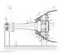
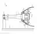
The FIGURE shows a cross section view of a steam turbine.
DETAILED DESCRIPTION OF INVENTION
The FIGURE shows an embodiment of a turbomachine, designed as a steam turbine 1. This steam turbine 1 comprises, in essence, a rotor 3 which is mounted such that it can rotate about an axis of rotation 2, on which rotor a first rotor blade stage 5, a second rotor blade stage 6 and a third rotor blade stage 7 are arranged on the rotor surface 4. The steam turbine 1 further comprises a casing (not shown in more detail) which is arranged around the rotatably mounted rotor 3. A first guide vane stage 8, a second guide vane stage 9 and a third guide vane stage 10 are arranged on the casing.
A flow path 11 is formed between the first 5, second 6 and third 7 rotor blade stages and the first 8, second 9 and third 10 guide vane stages, through which flow path steam flows in operation. The rotor 3 is mounted on a base 12 by means of a first bearing 13 and a second bearing 14. The first bearing 13 is arranged at a first end 15 of the rotor 3. The second bearing 14 is arranged at a second end 16.
In this context, the second bearing 14 is arranged in the flow path 11 upstream of the third rotor blade stage 7, that is to say consequently the final rotor blade stage. The bearing comprises a bearing casing 17 which is arranged around the second bearing 14. A bearing support 19 formed as a guide vane is arranged on the bearing casing. Since the bearing support 19 formed as a guide vane is arranged in the flow path 11, this bearing support 19 formed as a guide vane participates in the conversion of the energy of the steam in the flow path 11.
A diffuser 20, in which a pressure recovery of the steam in the flow path 11 takes place, is arranged downstream of the third rotor blade stage 7.
In alternative embodiments, the bearing support 19 formed as a guide vane, with the second bearing 14, can also be arranged upstream of the second rotor blade stage 6 or even further upstream in the flow path 11.
Devices 21 for exchanging energy and signals are provided in the bearing support 19 formed as a guide vane.
The rotor (3) has, as seen in the flow direction, a first, second, penultimate and final rotor blade row.
The casing has, as seen in the flow direction, a first, second, penultimate and final guide vane row.
The second bearing is arranged between the penultimate and the final rotor blade rows.
Claims
1. A turbomachine, comprising
a rotor which is mounted rotatably and comprises rotor blades, and
a casing which is arranged about the rotor,
wherein the casing comprises guide vanes, a first bearing and a second bearing for mounting the rotor,
wherein the rotor has, as seen in a flow direction, a first, second, penultimate and a final rotor blade row and the casing has a first, second, penultimate and a final guide vane row, and
wherein the second bearing is arranged in the flow direction between the penultimate and the final rotor blade rows.
2. The turbomachine as claimed in claim 1, wherein the second bearing has a bearing casing and a bearing support formed as guide vanes.
3. The turbomachine as claimed in claim 1, wherein a diffuser is arranged downstream of the final rotor blade row, as seen in the flow direction.
4. The turbomachine as claimed in claim 1, wherein devices for exchanging energy and signals are provided in the bearing support formed as a guide vane.
5. The turbomachine of claim 1, wherein the turbomachine comprises a steam turbine.
Images & Drawings included:
Sources:
- United States Patent and Trademark Office - verify current appl. status at the USPTO↗
Recent applications in this class:
- » 20250075639 2025-03-06
DUCTING ARRANGEMENT FOR A GAS TURBINE ENGINE - » 20240392698 2024-11-28
GAS TURBINE ENGINE SUPPORT STRUCTURE WITH INTERNAL LATTICE - » 20240384669 2024-11-21
TOOL FOR ALIGNMENT OF SEAL SEGMENTS - » 20240352874 2024-10-24
ROTATING-MACHINE CASING SUPPORT STRUCTURE AND ROTATING MACHINE - » 20240295179 2024-09-05
GASKET FOR TURBINE ENGINE AND TURBINE MOUNT ASSEMBLY - » 20240287917 2024-08-29
Aircraft turbine engine assembly comprising a support for equipment - » 20240175377 2024-05-30
Offshore steam turbine generator unit and installing method - » 20240141805 2024-05-02
Gas turbine engine support structure with internal lattice - » 20240117757 2024-04-11
TURBOMACHINERY INSTALLATION FOR AN OFFSHORE PLATFORM - » 20240003269 2024-01-04
System and method for installation or removal of one or more combustion cans
Recent applications for this Assignee:
- » 20250166165 2025-05-22
TRAINING SYSTEMS FOR SURFACE ANOMALY DETECTION - » 20250117920 2025-04-10
SELF-SUPERVISED ANOMALY DETECTION FRAMEWORK FOR VISUAL QUALITY INSPECTION IN MANUFACTRUING - » 20250108504 2025-04-03
PLANNING HINT GENERATION FOR COLLISION FREE MOTIONS - » 20250097699 2025-03-20
NETWORK MANAGEMENT IN AN INTERNET-OF-THINGS (IOT) ENVIRONMENT - » 20250085928 2025-03-13
INTELLIGENT DEVICE EXTENSION FOR BUILDING SOFTWARE APPLICATIONS - » 20250028517 2025-01-23
SYSTEM AND METHOD FOR RELIABLE OVER-THE-AIR FIRMWARE UPDATES - » 20250004437 2025-01-02
Low Code Engineering Function Orchestrator - » 20240427304 2024-12-26
SYSTEM AND METHOD FOR ENABLING SCALABLE PROCESSING THROUGHPUT OF HIGH-VOLUME DATA ON INDUSTRIAL CONTROLLERS - » 20240419129 2024-12-19
Method and system for providing time-critical control applications - » 20240418560 2024-12-19
Calibration method for a flow measurement system, flow measurement system and computer program product