Metal cans with peelable lids
US20150217907A1
2015-08-06
14/421,460
2013-08-06
✅ Patent granted
US 9,932,152 B2
2018-04-03
WO; PCT/GB2013/052093; 20130806
WO; WO2014/027180; 20140220
Carson Gross
Baker & Hostetler LLP
2034-10-05
Abstract:
A method of sealing a peelable lid to a circumferential and inwardly projecting flange formed in a tubular metal can body, where the flange has a sealing surface having a substantially V-shaped profile. The method comprises pressing the peelable lid against the sealing surface of the flange using a punch, an engagement surface of the punch having a generally V-shaped profile such that the apex of the punch presses the peelable lid into the valley of the engagement surface of the flange.
Assignee:
- Crown Packaging Technology, Inc 211 🇺🇸 Alsip, IL, United States
Applicant:
Interested in similar patents?
Get notified when new applications in this technology area are published.
Classification:
B65D43/0233 » CPC main
Lids or covers for rigid or semi-rigid containers; Removable lids or covers without integral tamper element secured by rolling or other plastic deformation
B32B38/00 IPC
Ancillary operations in connection with laminating processes
B32B38/0012 » CPC further
Ancillary operations in connection with laminating processes Mechanical treatment, e.g. roughening, deforming, stretching
B32B2435/02 » CPC further
Closures, end caps, stoppers for containers
B65D2543/00425 » CPC further
Lids or covers essentially for box-like containers; Details of lids or covers for rigid or semi-rigid containers Lids or covers welded or adhered to the container
B65D43/02 IPC
Lids or covers for rigid or semi-rigid containers Removable lids or covers
B32B37/18 » CPC further
Methods or apparatus for laminating, e.g. by curing or by ultrasonic bonding characterised by the properties of the layers with all layers existing as coherent layers before laminating involving the assembly of discrete sheets or panels only
B65D1/12 » CPC further
Containers having bodies formed in one piece, e.g. by casting metallic material, by moulding plastics, by blowing vitreous material, by throwing ceramic material, by moulding pulped fibrous material, by deep-drawing operations performed on sheet material Cans, casks, barrels, or drums
B29C66/131 » CPC further
General aspects of processes or apparatus for joining preformed parts; General aspects dealing with the joint area or with the area to be joined; Particular design of joint configurations particular design of the joint cross-sections; Single flanged joints; Fin-type joints; Single hem joints; Edge joints; Interpenetrating fingered joints; Other specific particular designs of joint cross-sections not provided for in groups - Single flanged joints, i.e. one of the parts to be joined being rigid and flanged in the joint area
B65B7/2878 » CPC further
Closing containers or receptacles after filling; Closing semi-rigid or rigid containers or receptacles not deformed by, or not taking-up shape of, contents, e.g. boxes or cartons by applying separate preformed closures, e.g. lids, covers; Securing closures on containers by heat-sealing
B65D17/503 » CPC further
Rigid or semi-rigid containers specially constructed to be opened by cutting or piercing, or by tearing of frangible members or portions; Non-integral frangible members applied to, or inserted in, preformed openings, e.g. tearable strips or plastic plugs; Flexible tape or foil-like material applied to the internal part of the container wall only
B29C66/53461 » CPC further
General aspects of processes or apparatus for joining preformed parts; General aspects of joining tubular articles; General aspects of joining long products, i.e. bars or profiled elements; General aspects of joining single elements to tubular articles, hollow articles or bars; General aspects of joining several hollow-preforms to form hollow or tubular articles; Joining tubular articles, profiled elements or bars; Joining single elements to tubular articles, hollow articles or bars; Joining several hollow-preforms to form hollow or tubular articles; Joining single elements to tubular articles, hollow articles or bars; Joining single elements to open ends of tubular or hollow articles or to the ends of bars said single elements being substantially flat joining substantially flat covers and/or substantially flat bottoms to open ends of container bodies
B29C66/723 » CPC further
General aspects of processes or apparatus for joining preformed parts characterised by the composition, physical properties or the structure of the material of the parts to be joined; Joining with non-plastics material characterised by the structure of the material of the parts to be joined being multi-layered
B29C66/742 » CPC further
General aspects of processes or apparatus for joining preformed parts characterised by the composition, physical properties or the structure of the material of the parts to be joined; Joining with non-plastics material; Joining plastics material to non-plastics material to metals or their alloys
B29C66/8322 » CPC further
General aspects of processes or apparatus for joining preformed parts; General aspects of machine operations or constructions and parts thereof characterised by the movement of the joining or pressing tools; Reciprocating joining or pressing tools Joining or pressing tools reciprocating along one axis
B29L2031/717 » CPC further
Other particular articles; Containers; Packaging elements or accessories, Packages Cans, tins
B65D17/50 IPC
Rigid or semi-rigid containers specially constructed to be opened by cutting or piercing, or by tearing of frangible members or portions Non-integral frangible members applied to, or inserted in, preformed openings, e.g. tearable strips or plastic plugs
B29C65/00 IPC
Joining of preformed parts ; Apparatus therefor
B65B7/28 IPC
Closing containers or receptacles after filling; Closing semi-rigid or rigid containers or receptacles not deformed by, or not taking-up shape of, contents, e.g. boxes or cartons by applying separate preformed closures, e.g. lids, covers
B29C65/18 » CPC further
Joining of preformed parts ; Apparatus therefor by heating, with or without pressure using heated tools
B29C65/76 » CPC further
Joining of preformed parts ; Apparatus therefor Making non-permanent or releasable joints
B29C66/112 » CPC further
General aspects of processes or apparatus for joining preformed parts; General aspects dealing with the joint area or with the area to be joined; Particular design of joint configurations particular design of the joint cross-sections; Joint cross-sections comprising a single joint-segment, i.e. one of the parts to be joined comprising a single joint-segment in the joint cross-section Single lapped joints
B65D1/40 » CPC further
Containers having bodies formed in one piece, e.g. by casting metallic material, by moulding plastics, by blowing vitreous material, by throwing ceramic material, by moulding pulped fibrous material, by deep-drawing operations performed on sheet material Details of walls
Description
TECHNICAL FIELD
The present invention relates to metal cans with peelable lids and in particular to the provision of a metal can having a flange to provide a surface for sealing the can with a peelable lid.
BACKGROUND
Cans are typically either two-piece or three-piece cans. In the case of a two-piece can, a can body is formed by punching a metal plate to form a cylinder closed at one end. Once the can is filled, the open end is then typically closed by seaming a lid to the can body. In the case of a three-piece can, a can body, open at both ends, is formed by rolling and seaming a metal plate. A first end is closed by typically seaming a lid to the can body. Once the can is filled and the second end is closed by typically seaming a lid to the can body.
FR 2639561 discloses a metal can and a method of manufacturing the same, the metal can comprising an internal annular flange to which a peelable lid can be heat-sealed in order to hermetically seal an interior space of the can. The peelable lid has a heat sealable layer which is used to hermetically bond the lid to the flange. An alternative heat sealing approach could involve providing adhesive around the upper surface of the flange and/or around the under surface of the peelable lid, heating the flange and applying downward pressure.
For some markets, the type of metal can described in FR 2639561 may be perfectly adequate. However, for more specialised markets, for example the infant formula market (i.e. metal cans that are used to store baby milk powder), where the seals are required to have very high performances even in the most hostile of environments, these known cans may not be suitable.
Before being introduced into the market, such specialised metal cans are required to undergo a series of stringent tests to ensure that they meet the necessary safety requirements. For example, metal cans may be tested to ensure that they do not lose their hermetic seal even when stored at high ambient temperatures such as 45° C. for periods in excess of 3 months and with a pressure difference from inside to outside of the can, for example of 700 mbar (70 kPa). Typically the external pressure is standard (ambient) air pressure and the internal pressure is negative, often referred to as a “vacuum”. Under such conditions, it has been found that metal cans made in accordance with those described in the prior art are prone to suffering from “creep” in the seal. Creep is the tendency for the peelable lid to be pulled inward across the flange. This can reduce the effectiveness of the seal between the peelable lid and the flange, and in some cases may cause the seal to fail completely. Metal cans that suffer from creep in this way cannot be used in the infant formula market as the seal is not deemed to seal the product to a high enough standard.
SUMMARY OF INVENTION
It is an object of the present invention to overcome or at least mitigate the problems discussed above which result from creep in the seal between a metal can with a flange and a peelable lid.
According to a first embodiment of the present invention there is provided a method of sealing a peelable lid to a circumferential and inwardly projecting flange formed in a tubular metal can body, where the flange has a sealing surface having a substantially V-shaped profile, the method comprising pressing the peelable lid against the sealing surface of the flange using a punch, an engagement surface of the punch having a generally V-shaped profile such that the apex of the punch presses the peelable lid into the valley of the engagement surface of the flange.
Heat may be applied to the peelable lid and/or the flange as the peelable lid is pressed against the sealing surface of the flange.
Embodiments of the present invention provide an improved metal can that is capable of providing a superior hermetic seal.
Preferably, said step of pressing the peelable lid against the sealing surface of the flange using a punch substantially eliminates air pockets from between the peelable lid and the sealing surface of the flange.
BRIEF DESCRIPTION OF DRAWINGS
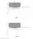
FIG. 1 illustrates a cross section through part of the side wall of a can with a flange as currently known in the prior art;
FIG. 2 illustrates a cross section through part of the side wall and a punch with a generally V-shaped engagement surface at a first stage of a sealing operation according to an embodiment of the present invention;
FIG. 3 illustrates the sealing operation at a second stage;
FIG. 4 illustrates the sealing operation at a third stage;
FIG. 5 illustrates the sealing operation at a fourth stage;
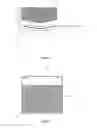
FIG. 6 illustrates a cross-sectional view of a metal can body with a flange and a peelable lid sealed to the flange using the method of FIGS. 2 to 5; and
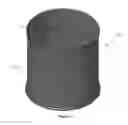
FIG. 7 is a perspective view of a metal can body according to an embodiment of the invention.
DESCRIPTION OF EMBODIMENTS
The following discussion relates to metal cans that are provided with peelable lids that hermetically seal the can, and which can be peeled back and removed to open the can and provide access to the contents stored therein. The metal cans may be either two-piece cans or three-piece cans.
As discussed above, known metal cans that are provided with flanges to seal with a peelable lid are often not able to be sealed to a high enough standard to pass the stringent tests required for certain high specification products, in particular infant formula powder.
FIG. 1 illustrates a cross section through part of the side wall 2 of a metal can that has a flange 1 such as is known in the prior art. The upper surface of the flange does not provide a perfectly flat surface onto which a peelable lid can be sealed. Tests show that it is extremely difficult to obtain a completely flat upper surface on this type of flange, and typically the upper surface of the flange adopts a generally “V-shaped” profile with two radially inner and outer portions (3 and 4) being raised above an area between them at a lower level (B′). This profile arises when the initially dome shaped upper surface of the flange collapse down in the centre region (N and B′).
The horizontal dotted line A indicates that, during a typical sealing process, when a peelable lid is positioned onto the upper surface of the flange from above using a flat punch, it would in fact only seal to the upper surface of the flange at the positions 3 and 4. There is a significant “trough” between arrows B and B′ where air would be trapped between the two sealed portions at 3 and 4, thus preventing this area from being properly sealed. As a consequence, there is a substantial reduction in the overall sealing area between the peelable lid and the flange, and this greatly weakens the seal in shear mode and increases the possibility of the seal suffering from creep.
A method of sealing a peelable lid to a metal can comprising an inwardly projecting flange will now be described, with reference to FIGS. 3 to 5, and which enables the formation of a substantially continuous seal across the radial extent of the flange in order to achieve a more robust seal. This is facilitated by using a punch that has an engagement surface having a generally V-shaped profile to press the peelable lid against the flange sealing surface. The generally V-shaped engagement surface of the punch reduces the size of, or even eliminates, “pockets” of trapped air between the peelable lid and the upper surface of the flange.
FIG. 2 illustrates in cross section a part of the side wall 2 of a metal can and a punch 10 at the start of a sealing operation in which the peelable lid 12 is “punched” into place. The punch 10 has a generally V-shaped engagement surface 11 which approximately conforms with the generally V-shaped profile of the sealing surface of the flange 1. [It will be appreciated that the punch 10 is generally ring shaped for insertion into the can body such that in use it extends around the inner periphery of the can body for engagement with the flange.]
During the heat sealing process, the punch 10 presses the peelable lid 12 down on the flange 1 using a force F. The seal is formed initially in the middle of the radial extent of the flange 1 at point P where the apex of the punch 10 presses the peelable lid 12 into the trough of the engagement surface of the flange 1. Then, as shown in FIG. 3, as the punch is pressed down onto the flange, the peelable lid 12 adopts the V-shaped profile of the punch 10, and a seal is formed between the peelable lid 12 and the flange 1.
The seal is made using a heat-sealable material, for example a thermoplastic material, located between the peelable lid and the convex upper surface of the flange. The V-shaped profile of the engagement surface of the punch 10 allows any air that would otherwise be trapped, to escape from between the peelable lid and the sealing surface of the flange at each of the sides before the full seal is made across substantially the whole radial extent of the flange.
As illustrated in FIG. 4, the shape of the sealing surface of the flange may also be changed by the pressure applied by the punch 10. This can further reduce the extent of the non-sealed areas between the peelable lid and the sealing surface of the flange.
FIG. 5 illustrates a cross section of the wall of the metal can 2 after the peelable lid 12 has been heat-sealed to the sealing surface of the flange 1 and the punch 10 withdrawn. The arrow S shows the substantially uninterrupted width of the seal that is formed over most of the radial extent of the flange.
FIG. 6 illustrates a cross section through a metal can 15 storing a powder 16. The metal can has a flange 1 formed in the can wall 2. The flange 1 provides a sealing surface to which a peelable lid 12 has been heat sealed using a punch having an engagement surface with a generally V-shaped profile. The peelable lid 12 can comprise a tab, or similar, such that the consumer can more easily remove the peelable lid by peeling it off the flange. The can is provided with a non-removable base, or “can bottom”, 17 which seals the opening at the bottom end of the can. Although not shown in FIG. 6, the can may further be provided with a removable plastic overcap that is placed over the opening at the top end of the can. This plastic overcap enables the can to be reclosed once the seal has been broken and the peelable lid removed.
The flange 1 is shown in FIG. 6 as being near the open end of the metal can. However the flange may be formed lower down the can wall, thus enabling the seal to separate the can into two distinct compartments. For example, the lower compartment that is hermetically sealed by the peelable lid may contain infant formula powder, and the upper compartment may contain a scoop or spoon. A further flange may be provided towards the top of the can to seal the section of the can containing the scoop to ensure that it is kept in a sterile environment prior to a consumer opening and using it.
It is also possible to form flanges at both open ends of a tubular can body (which has a welded side seam) and to close both ends with respective peelable lids.
During the manufacturing process for cans such as those described herein, a can manufacturer may manufacture tubular metal cans with the peelable lids in place but with the bottom ends left open. The cans, with separate bottom ends and plastic overcaps, will then be sent to the manufacturer's customers. The customer can then fill the cans with product through the open bottoms before sealing the cans by seaming the non-removable can bottoms in place. The plastic overcaps can then be placed on the top end of the cans above the peelable lids. If required, a spoon or scoop can be placed in the can on top of the peelable lid, prior to the plastic overcap being put in place.
FIG. 7 illustrates a perspective view of a metal can 15 from above. This view shows that the flange 1 is formed in the can wall 2 part-way down its length, and that the flange extends around the entire inner circumference of the metal can 15.
It will be appreciated by the person of skill in the art that various modifications may be made to the above described embodiments without departing from the scope of the present invention. For example, the peelable lid may be of a plastic material, or may be a multi-layer structure which includes a ceramic layer such as silica or alumina instead of metal.
Claims
1. A method of sealing a peelable lid to a circumferential and inwardly projecting flange formed in a tubular metal can body,
comprising the steps of:
(i) forming a V-shaped profile into a sealing surface of the flange; and
(ii) engaging a V-shaped engagement profile of a punch with the peelable lid to press the peelable lid against the flange such that the apex of the punch engagement profile presses the peelable lid into the valley of the flange profile.
2. A method according to claim 1, further comprising the step of applying heat to at least one of the peelable lid and the flange as the peelable lid is pressed against the flange.
3. A method according to claim 1, wherein said step of pressing the peelable lid against the sealing surface of the flange using a punch substantially diminishes air pockets from between the peelable lid and the sealing surface of the flange.
4. A method according to claim 3, wherein the step of pressing the peelable lid against the sealing surface of the flange using a punch substantially eliminates air pockets from between the peelable lid and the sealing surface of the flange.
5. A method according to claim 1, wherein the forming step (i) and the pressing step (ii) are performed by a single motion of the punch such that the pressing step (ii) forms the V-shaped profile in the sealing surface of the flange.
6. A tubular metal can combination comprising:
a tubular sidewall including an inwardly projecting, circumferential flange, the flange having a sealing surface on an outboard surface thereof, the sealing surface having a V-shaped profile; and
a peelable lid in sealing contact with the sealing surface of the flange, the lid having a V-shaped portion that is located in the V-shaped profile of the flange sealing surface.
7. A tubular metal can combination of claim 6, wherein the V-shaped portion of the lid has a shape that matches the V-shaped profile of the flange.
8. A tubular metal can combination of claim 6, wherein the lid is adhered to the flange by a heat seal.
9. A tubular metal can combination of claim 6, wherein the sealing contact between the lid and the flange is substantially free of air pockets.
Images & Drawings included:


Sources:
- United States Patent and Trademark Office - verify current appl. status at the USPTO↗
Similar patent applications:
Recent applications in this class:
- » 20230067228 2023-03-02
STORAGE SYSTEM WITH MAGNETIC SEALING CLOSURE - » 20210188491 2021-06-24
Systems and methods for containers with locking lug and recess - » 20190077551 2019-03-14
Method of manufacturing an improved disposable lid - » 20180170629 2018-06-21
Systems and methods for containers with locking lug and recess - » 20180086513 2018-03-29
Method of manufacturing an improved disposable lid - » 20180086512 2018-03-29
Method of manufacturing an improved disposable lid - » 20170073125 2017-03-16
Container and method for preserving air-sensitive materials - » 20150360828 2015-12-17
REINFORCED FOIL MEMBRANE - » 20150053680 2015-02-26
Cover material for packaging container for retort sterilization - » 20050189356 2005-09-01
Beaded crimp lid for improved container seal
Recent applications for this Assignee:
- » 20230011029 2023-01-12
FOOD TIN WITH VACUUM SEALED LID - » 20220411140 2022-12-29
METAL CONTAINER AND METAL CLOSURE THEREOF - » 20220305543 2022-09-29
CAN BASE FORMING - » 20220089318 2022-03-24
Easy open end with increased panel stiffness - » 20220088918 2022-03-24
Can body decorator having a mandrel pre-spin assembly and over-varnish unit - » 20220032405 2022-02-03
Welding of can bodies - » 20220024646 2022-01-27
Low migration container - » 20210362537 2021-11-25
Tab press and method of marking indicia on tab stock - » 20210291249 2021-09-23
Metal containers and methods of manufacture - » 20200376535 2020-12-03
Can base forming