FAN SERIAL CONNECTION STRUCTURE
US20150233391A1
2015-08-20
14/183,485
2014-02-18
Abstract:
A fan serial connection structure includes a series fan assembly and a connection member. The series fan assembly includes a first fan and a second fan correspondingly serially connected with the first fan. The connection member is disposed on one side of the series fan assembly. The connection member has a first face and a second face opposite to the first face. The first face is correspondingly assembled with the side of the series fan assembly. According to the above structural design, the co-vibration of the series fan is offset or restrained to greatly reduce the vibration of the fan and lower the noise.
Assignee:
- ASIA VITAL COMPONENTS (CHINA) CO., LTD. 2 🇨🇳 Shajing Branch, China
Interested in similar patents?
Get notified when new applications in this technology area are published.
Classification:
F04D29/668 » CPC main
Details, component parts, or accessories; Combating cavitation, whirls, noise, vibration or the like ; Balancing especially adapted for elastic fluid pumps damping or preventing mechanical vibrations
F04D29/601 » CPC further
Details, component parts, or accessories; Mounting; Assembling; Disassembling specially adapted for elastic fluid pumps
F04D29/66 IPC
Details, component parts, or accessories Combating cavitation, whirls, noise, vibration or the like ; Balancing
F04D29/60 IPC
Details, component parts, or accessories Mounting; Assembling; Disassembling
Description
BACKGROUND OF THE INVENTION
1. Field of the Invention
The present invention relates generally to a fan serial connection structure, and more particularly to a fan serial connection structure, which can greatly reduce the vibration of the fan and lower the noise.
2. Description of the Related Art
Along with the continuous advance of sciences and technologies, the reliance of peoples on various electronic apparatuses has more and more increased. In operation, the internal components of the electronic products (such as computers and laptops) will generate high heat. The heat must be dissipated to outer side of the electronic products in time. Otherwise, the problem of overheating will take place. Therefore, most of the electronic products are provided with fans disposed therein for keeping the electronic products working at an operation temperature within a range.
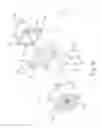
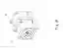
Please refer to FIGS. 1A and 1B. The fan frames 10 of the current series fan 1 have the same size. The fan frames 10 are assembled with a fan impeller 11, a motor (not shown), etc. to form the fan. In operation, according to the design principle of the motor torque operation, the fan frame 11 will inevitably vibrate. Especially, with respect to a series fan, the fan frames 10 are serially connected simply by means of the latch structures 12 between the fan frames 10 along the central shaft of the fan. Therefore, the vibration state of the fan cannot be changed. As a result, when the fan impellers 11 inside the fan frames 10 operate and rotate at the same time, under the inter-affection of the vibration frequency of the fan impellers 11, the two fan frames 10 will severely resonate under resonation effect. The resonation will be directly transmitted outward form the fan frames 10. The hard disk (such as the hard disk in a server) of the mainframe system of an electronic product is quite sensitive to vibration. However, the conventional one-piece fan frame 10 can hardly reduce the vibration. In some more serious cases, the vibration of the motor and the fan impeller 11 will even interfere with the normal work of other electronic components. This will lead to deterioration of the performance of the system. Moreover, the resonation is always accompanied by loud noise.
According to the above, the conventional device has the following shortcomings:
1. The vibration of the fan can be hardly effectively reduced.
2. The vibration of the fan will make loud noise.
3. The reading efficiency of the hard disk of the system is lowered.
SUMMARY OF THE INVENTION
It is therefore a primary object of the present invention to provide a fan serial connection structure, which can greatly reduce the vibration of the fan.
It is a further object of the present invention to provide the above fan serial connection structure, which can greatly lower the noise caused by the vibration of the fan.
To achieve the above and other objects, the fan serial connection structure of the present invention includes a series fan assembly and a connection member. The series fan assembly includes a first fan and a second fan correspondingly serially connected with the first fan. The first fan has a first fan frame and a first flow passage passing through the first fan frame. The second fan has a second fan frame and a second flow passage passing through the second fan frame. The second flow passage communicates with the first flow passage.
The connection member is disposed on one side of the series fan assembly. The connection member has a first face and a second face opposite to the first face. The first face is correspondingly assembled with the side of the series fan assembly.
According to the above structural design of the present invention, the first face of the connection member is correspondingly fixedly assembled with the side of the series fan assembly. In this case, when the series fan operates, the co-vibration of the series fan is greatly reduced and the noise caused by the vibration of the series fan is greatly lowered. In addition, the reading efficiency of the hard disk of the system is enhanced.
BRIEF DESCRIPTION OF THE DRAWINGS
The structure and the technical means adopted by the present invention to achieve the above and other objects can be best understood by referring to the following detailed description of the preferred embodiments and the accompanying drawings, wherein:
FIG. 1A is a perspective exploded view of a conventional fan serial connection structure;
FIG. 1B is a perspective assembled view of the conventional fan serial connection structure;
FIG. 2A is a perspective exploded view of a first embodiment of the fan serial connection structure of the present invention;
FIG. 2B is a perspective assembled view of the first embodiment of the fan serial connection structure of the present invention;
FIG. 3A is a perspective exploded view of a second embodiment of the fan serial connection structure of the present invention;
FIG. 3B is a perspective assembled view of the second embodiment of the fan serial connection structure of the present invention;
FIG. 4A is a perspective exploded view of a third embodiment of the fan serial connection structure of the present invention;
FIG. 4B is a perspective assembled view of the third embodiment of the fan serial connection structure of the present invention;
FIG. 5A is a perspective exploded view of a fourth embodiment of the fan serial connection structure of the present invention;
FIG. 5B is a perspective assembled view of the fourth embodiment of the fan serial connection structure of the present invention;
FIG. 6A is a perspective exploded view of a fifth embodiment of the fan serial connection structure of the present invention; and
FIG. 6B is a perspective assembled view of the fifth embodiment of the fan serial connection structure of the present invention.
DETAILED DESCRIPTION OF THE PREFERRED EMBODIMENTS
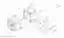
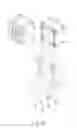
Please refer to FIGS. 2A and 2B. FIG. 2A is a perspective exploded view of a first embodiment of the fan serial connection structure of the present invention. FIG. 2B is a perspective assembled view of the first embodiment of the fan serial connection structure of the present invention. According to the first embodiment, the fan serial connection structure of the present invention includes a series fan assembly 2 and a connection member 3. The series fan assembly 2 includes a first fan 20 and a second fan 21 correspondingly serially connected with the first fan 20. The first fan 20 has a first fan frame 201 and a first flow passage 202 passing through the first fan frame 201. The second fan 21 has a second fan frame 211 and a second flow passage 212 passing through the second fan frame 211. The second flow passage 212 communicates with the first flow passage 202. The first and second fans 20, 21 are serially connected with each other by a means selected from a group consisting of engagement, locking, insertion, adhesion and latching.
The connection member 3 is disposed on one side of the series fan assembly 2. The connection member 3 has a first face 30 and a second face 31 opposite to the first face 30. The first face 30 is correspondingly assembled with the side of the series fan assembly 2. The connection member 3 is formed with multiple perforations 32 passing through the connection member 3 from the first face 30 to the second face 31.
The side of the series fan assembly 2 is formed with multiple through holes 213 corresponding to the perforations 32. Multiple locking members 4 are passed through the perforations 32 and the through holes 213.
According to the above structural design of the present invention, the first face 30 of the connection member 3 is correspondingly fixedly assembled with the side of the series fan assembly 2 by means of the locking members 4. In this case, when the fans operate, the vibration frequencies of the fans are unified to offset or restrain the co-vibration of the series fan so as to greatly reduce the vibration and noise. Therefore, the present invention solves the problem of the conventional series fan that the first and second fans are simply directly assembled with each other and the vibration frequency cannot be changed. In addition, the reading efficiency of the hard disk of the system is enhanced.
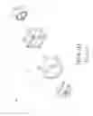
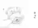
Please now refer to FIGS. 3A and 3B. FIG. 3A is a perspective exploded view of a second embodiment of the fan serial connection structure of the present invention. FIG. 3B is a perspective assembled view of the second embodiment of the fan serial connection structure of the present invention. The second embodiment is partially identical to the first embodiment in component and relationship between the components and thus will not be repeatedly described hereinafter. The second embodiment is mainly different from the first embodiment in that the connection member 3 further includes at least one assembling member 5 formed with a passageway 52. The assembling member 5 is assembled with the series fan assembly 2. The assembling member 5 has a first end face 50 and a second end face 51 opposite to the first end face 50. The passageway 52 passes through the assembling member 5 from the first end face 50 to the second end face 51.
The assembling member 5 is formed with multiple assembling sections 53. The series fan assembly 2 is formed with multiple connection sections 214 correspondingly assembled with the assembling sections 53. The assembling sections 53 can be holes, sockets, mortises or posts. The connection sections 214 can be holes, sockets, mortises or posts.
The first fan 20 further has a first opening 2021 and a second opening 2022 opposite to the first opening 2021. The first flow passage 202 is defined between the first and second openings 2021, 2022. The second fan 21 further has a third opening 2121 and a fourth opening 2122 opposite to the third opening 2121. The second flow passage 212 is defined between the third and fourth openings 2121, 2122. The fourth opening 2122 correspondingly communicates with the second opening 2022.
In this embodiment, the assembling member 5 is disposed between the second and fourth openings 2022, 2122. The first end face 50 is assembled with the second opening 2022, while the second end face 51 is assembled with the fourth opening 2122. The passageway 52 correspondingly communicates with the first and second flow passages 202, 212. In this embodiment, the series fan assembly 2 is assembled with the assembling member 5 by means of engagement. In practice, the first and second fans 20, 21 can be assembled with the first and second end faces 50, 51 by any other means that can securely connect the first and second fans 20, 21 with the first and second end faces 50, 51, for example, by means of slide rail (as shown in FIGS. 4A and 4B, a third embodiment of the present invention), locking, insertion, adhesion or latching. This is not limited.
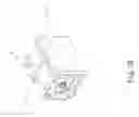
Please now refer to FIGS. 5A and 5B. FIG. 5A is a perspective exploded view of a fourth embodiment of the fan serial connection structure of the present invention. FIG. 5B is a perspective assembled view of the fourth embodiment of the fan serial connection structure of the present invention. The fourth embodiment is partially identical to the first embodiment in component and relationship between the components and thus will not be repeatedly described hereinafter. The fourth embodiment is mainly different from the first embodiment in that the connection member 3 has two assembling members 5 respectively disposed at the first and third openings 2021, 2121 and assembled with the first and third openings 2021, 2121. The passageways 52 of the assembling members 5 respectively correspondingly communicate with the first and second flow passages 202, 212.
In this embodiment, the series fan assembly 2 is assembled with the assembling members 5 by means of locking. In practice, the first and second fans 20, 21 can be assembled with the first and second end faces 50, 51 by any other means that can securely connect the first and second fans 20, 21 with the first and second end faces 50, 51, for example, by means of slide rail (as shown in FIGS. 6A and 6B, a fifth embodiment of the present invention), engagement, insertion, adhesion or latching. This is not limited.
According to the above structural design, the connection sections 214 of the series fan assembly 2 are correspondingly assembled with the connection member 3 and the assembling sections 53 of the assembling members 5. Accordingly, the series fan assembly 2 can be more securely connected with the connection member 3 and the assembling members 5. In this case, when the fans operate, the vibration frequencies of the fans are unified to offset or restrain the co-vibration of the series fan so as to greatly reduce the vibration and noise. Therefore, the present invention solves the problem of the conventional series fan that the first and second fans are simply directly assembled with each other and the vibration frequency cannot be changed. In addition, the reading efficiency of the hard disk of the system is enhanced.
In conclusion, in comparison with the conventional series fan, the present invention has the following advantages:
1. The vibration of the fan is greatly reduced.
2. The noise caused by the vibration of the fan is lowered.
3. The reading efficiency of the hard disk of the system is enhanced.
The present invention has been described with the above embodiments thereof and it is understood that many changes and modifications in the above embodiments can be carried out without departing from the scope and the spirit of the invention that is intended to be limited only by the appended claims.
Claims
What is claimed is:1. A fan serial connection structure comprising:
a series fan assembly including a first fan and a second fan correspondingly serially connected with the first fan, the first fan having a first fan frame and a first flow passage passing through the first fan frame, the second fan having a second fan frame and a second flow passage passing through the second fan frame, the second flow passage communicating with the first flow passage; and
a connection member disposed on one side of the series fan assembly, the connection member having a first face and a second face opposite to the first face, the first face being correspondingly assembled with the side of the series fan assembly.
2. The fan serial connection structure as claimed in claim 1, wherein the connection member is formed with multiple perforations passing through the connection member from the first face to the second face, the side of the series fan assembly being formed with multiple through holes corresponding to the perforations, multiple locking members being passed through the perforations and the through holes.
3. The fan serial connection structure as claimed in claim 1, wherein the first and second fans are serially connected with each other by a means selected from a group consisting of engagement, locking, insertion, adhesion and latching.
4. The fan serial connection structure as claimed in claim 1, wherein the connection member further includes at least one assembling member formed with a passageway, the assembling member being assembled with the series fan assembly.
5. The fan serial connection structure as claimed in claim 4, wherein the assembling member has a first end face and a second end face opposite to the first end face, the passageway passing through the assembling member from the first end face to the second end face.
6. The fan serial connection structure as claimed in claim 5, wherein the first fan further has a first opening and a second opening opposite to the first opening, the first flow passage being defined between the first and second openings, the second fan further having a third opening and a fourth opening opposite to the third opening, the second flow passage being defined between the third and fourth openings, the fourth opening correspondingly communicating with the second opening.
7. The fan serial connection structure as claimed in claim 6, wherein the assembling member is disposed between the second and fourth openings, the first end face being assembled with the second opening, while the second end face being assembled with the fourth opening, the passageway correspondingly communicating with the first and second flow passages.
8. The fan serial connection structure as claimed in claim 7, wherein the series fan assembly is assembled with the assembling member by means of engagement, locking, insertion, adhesion, slide rail or latching.
9. The fan serial connection structure as claimed in claim 6, wherein the connection member has two assembling members respectively disposed at the first and third openings and assembled with the first and third openings, the passageways of the assembling members respectively correspondingly communicating with the first and second flow passages.
10. The fan serial connection structure as claimed in claim 9, wherein the series fan assembly is assembled with the assembling members by means of engagement, locking, insertion, adhesion, slide rail or latching.
11. The fan serial connection structure as claimed in claim 4, wherein the assembling member is formed with multiple assembling sections, the series fan assembly being formed with multiple connection sections correspondingly assembled with the assembling sections.
12. The fan serial connection structure as claimed in claim 11, wherein the assembling sections are holes, sockets, mortises or posts.
13. The fan serial connection structure as claimed in claim 11, wherein the connection sections are holes, sockets, mortises or posts.
Images & Drawings included:


Sources:
- United States Patent and Trademark Office - verify current appl. status at the USPTO↗
Similar patent applications:
- » 20150233392
Fan serial connection structure - » 20080008576
Shock-absorbent structure of serially-connected fans - » 20080124232
Serial fan assembly and connection structure thereof
Recent applications in this class:
- » 20250129796 2025-04-24
BLOWER DEVICE AND RESPIRATOR INCLUDING BLOWER DEVICE - » 20250129795 2025-04-24
FAN FOR GENERATING A COOLING AIR FLOW, COMPRISING AN ELASTIC DAMPING ELEMENT FOR DAMPING A TRANSMISSION OF VIBRATIONS - » 20240418184 2024-12-19
MOUNTING STRUCTURE FOR COMPRESSOR AND COMPRESSOR - » 20240352948 2024-10-24
A DAMPER FOR FAN - » 20240240651 2024-07-18
Damping device for damping shaft vibration - » 20240175448 2024-05-30
FAN UNIT - » 20240052853 2024-02-15
Axial fan - » 20230349395 2023-11-02
Blower device and respirator including blower device - » 20230323898 2023-10-12
Multistage centrifugal compressor - » 20230296115 2023-09-21
Rotary machine
Recent applications for this Assignee:
- » 20150233387 2015-08-20
Method of assembling a serial fan