Adjustable compact recessed lighting assembly with hangar bars
US20150233556A1
2015-08-20
14/183,424
2014-02-18
✅ Patent granted
US 10,139,059 B2
2018-11-27
-
-
Anh Mai | Steven Horikoshi
Cooley LLP
2034-02-18
Abstract:
A compact recessed lighting system is provided. The recessed lighting system includes a light source module and a driver coupled to a unified casting and within a shared junction box. The junction box may be coupled to a set of hangar holders that are movably coupled to a corresponding set of hangar bars. The junction box, including the light source module and driver installed therein, may move both 1) along the hangar bars and 2) along an axis perpendicular to the hangar bars. Accordingly, the junction box may be moved to rest in preferred location between a set of joists or beams in a structure. By being configured such that the junction box, along with the light source module and driver, is coupled to a unified set of moveable elements that position the combined structure, the recessed lighting system eliminates the added bulk and size of traditional recessed lighting systems.
Assignee:
- DMF, Inc. 54 🇺🇸 Carson, CA, United States
Applicant:
Interested in similar patents?
Get notified when new applications in this technology area are published.
Classification:
F21V21/14 » CPC main
Supporting, suspending, or attaching arrangements for lighting devices ; Hand grips Adjustable mountings
F21V17/10 » CPC further
Fastening of component parts of lighting devices, e.g. shades, globes, refractors, reflectors, filters, screens, grids or protective cages characterised by specific fastening means or way of fastening
F21V17/08 » CPC further
Fastening of component parts of lighting devices, e.g. shades, globes, refractors, reflectors, filters, screens, grids or protective cages onto the supporting or suspending arrangements of the lighting device, e.g. power cords, standards
F21V23/009 » CPC further
Arrangement of electric circuit elements in or on lighting devices the elements being electronics drivers or controllers for operating the light source, e.g. for a LED array enclosed in a casing the casing being inside the housing of the lighting device
F21S8/02 » CPC main
Lighting devices intended for fixed installation of recess-mounted type, e.g. downlighters
F21V23/00 IPC
Arrangement of electric circuit elements in or on lighting devices
F21S8/026 » CPC further
Lighting devices intended for fixed installation of recess-mounted type, e.g. downlighters intended to be recessed in a ceiling or like overhead structure, e.g. suspended ceiling
F21V21/048 » CPC further
Supporting, suspending, or attaching arrangements for lighting devices ; Hand grips; Wall, ceiling, or floor bases; Fixing pendants or arms to the bases; Recessed bases Mounting arrangements for fastening lighting devices to false ceiling frameworks
F21Y2115/10 » CPC further
Light-generating elements of semiconductor light sources Light-emitting diodes [LED]
F21V21/04 IPC
Supporting, suspending, or attaching arrangements for lighting devices ; Hand grips; Wall, ceiling, or floor bases; Fixing pendants or arms to the bases Recessed bases
Description
FIELD
An embodiment of the invention relates to recessed lighting systems that include a unified light source module and driver, coupled to a set of hangar bars.
BACKGROUND
Recessed lighting systems are typically installed or mounted into an opening in a ceiling or a wall. Modern recessed lighting systems generally consist of a trim, a light source module, a driver circuit, a “can” or housing, a junction box, and a set of hangar bars. The driver is insulated from other portions and components of the recessed lighting system, including the light source module, through the use of insulation provided by the junction box while the light source module is housed in the can. The driver is electrically coupled to the light source module through the use of wires or other conduits so that the driver can power the light source module to emit light.
The junction box, the can, and other components of the recessed lighting system are attached to the hangar bars such that the hangar bars may support the components of the recessed lighting system in a wall or ceiling of a structure. For example the junction box may be attached to the hangar bars through the use of screws and bolts, which anchor the junction box and driver. In contrast, the combined can and light source module, which is electrically connected to the junction box and driver, is moveable.
BRIEF DESCRIPTION OF THE DRAWINGS
The embodiments of the invention are illustrated by way of example and not by way of limitation in the figures of the accompanying drawings in which like references indicate similar elements. It should be noted that references to “an” or “one” embodiment of the invention in this disclosure are not necessarily to the same embodiment, and they mean at least one.
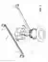
FIG. 1 shows an exploded view of a recessed lighting system according to one embodiment.
FIG. 2 shows a side view of a combined junction box, light source module, driver, unified casting, and trim of the recessed lighting system according to one embodiment.
FIG. 3 shows top and side views of a junction box according to one embodiment.
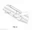
FIG. 4 shows a perspective view of a hangar holder according to one embodiment.
FIG. 5 shows how the junction box and hangar holders can be moved and positioned horizontally along hangar bars and vertically along the axis Y according to one embodiment.
FIG. 6 shows a perspective view of a screwdriver bending a tab of a hangar holder to lock the hangar holder in a position along the hangar bars according to one embodiment.
FIG. 7 shows a perspective view of a hangar holder according to another embodiment.
DETAILED DESCRIPTION
Several embodiments are described with reference to the appended drawings are now explained. While numerous details are set forth, it is understood that some embodiments of the invention may be practiced without these details. In other instances, well-known circuits, structures, and techniques have not been shown in detail so as not to obscure the understanding of this description.
FIG. 1 shows an exploded view of a recessed lighting system 1. The recessed lighting system 1 may include a junction box 2, a unified casting 3, a trim 4, a set of hangar bars 5, and a set of hangar holders 6. In some embodiments, the unified casting 3 may include a light source module 7 and a driver 8 in a single compact unit as shown in FIG. 2. As will be described in further detail below, the recessed lighting system 1 provides a more compact and cost effective design that allows the light source module 3 to be moved and adjusted while complying with various building and safety codes/regulations. Each of the elements of the recessed lighting system 1 will be explained by way of example below.
The junction box 2 is a structure that separates the inner components of the recessed lighting system 1, including electrical wires/cables, from the items inside a ceiling or crawl space (e.g., insulation) in which the junction box 2 has been installed. In one embodiment, the junction box 2 may be a single or double gang box with a fire rating of up to two hours as described in the National Electrical Code (NEC) and by the Underwriters Laboratories (UL). The junction box 2 may receive electrical wires 9A from an electrical system (e.g., 120 VAC or 277 VAC) within a building or structure in which the recessed lighting system 1 is installed. The electrical wires 9A from the structure may be connected to corresponding wires 9B of the unified casting 3, as will be described in greater detail below.
In one embodiment, the junction box 2 may include one or more tabs 10 for coupling the junction box 2 to the casting 3. The tabs 10 may be any device/component for receiving corresponding elements 11 of the casting 3 to firmly hold the weight of the unified casting 3, including the light source module 7 and the driver 8 which may be contained in the casting 3. The trim 4 may also be attached to the junction box 2 to hide at least the periphery of the junction box from view. As shown in FIG. 1, the tabs 10 include holes for receiving screws or bolts; however, in other embodiments the tabs 10 may facilitate a twist-and-lock friction connection with corresponding elements 11 of the casting 3 and without the use of separate tools or other devices. In still other embodiments, friction or tension clips may be utilized to retain the casting 3 inside the junction box 2.
In one embodiment, the junction box 2 acts as a heat barrier to block heat emitted by the light source module 7 and the driver 8 (See FIG. 2) from reaching possibly flammable items inside a ceiling or crawl space. Accordingly, the compact design may provide fire rating up to two hours. In these embodiments, the junction box 2 may be formed of metals, polymers, metal alloys, and/or other heat insulating materials. As shown in FIG. 1, the junction box 2 may be a polyhedron that defines a cavity 12 therein. However, in other embodiments, the side wall of the junction box 2 may be curved and have any suitable shape, including an ellipsoid, cone, or cylinder, so that the box is still capable of receiving therein the casting 3. The cavity 12 that is formed in the junction box 2 is larger than the casting 3 such that the casting 3 easily fits into the cavity 12, preferably without coming into direct contact with the side walls of the junction box 2. However, in other embodiments, the casting 3 may be sized to come into direct contact with the side walls of the junction box 2. The size of the cavity 12 may be pursuant to popular industry specifications for junction boxes and in compliance with any applicable building and safety codes/regulations. For example, as shown in the top and side views of FIG. 3, the junction box 2 may have a length of 3½ inches, a width of 3½ inches and a depth of 1½ inches. When coupled together, the combined junction box 2, casting 3, and trim 4 may have a height/depth of about 2 inches, e.g., no more than 3 inches. In one embodiment, the combined junction box 2, casting 3, and trim 4 may have a height/depth between 2-3 inches.
The casting 3 is a shell and/or enclosure that further prevents the exposure of heat from the light source module 7 and the driver 8 to the items inside a ceiling or crawl space (e.g., insulation) in which the recessed lighting system 1 has been installed. The casting 3 may be formed of metals, polymers, metal alloys, and/or other heat insulating materials. As shown in FIG. 1, the casting 3 may be a cylindrical structure; however, in other embodiments, the casting 3 may be any suitable shape, including an ellipsoid, cone, or polyhedron that is capable of housing the light source module 7 and the driver 8.
In one embodiment, the electrical wires 9A received by the junction box 2 from the electrical system of a building or structure may be coupled to the electrical wires 9B of the casting 3. As shown, the electrical wires 9A and 9B are connected together through the use of interlocking connectors that may be contained within the box 2 (together with the casting 3). However, in other embodiments, the electrical wires 9A may be coupled to the electrical wires 9B through the use of electrical caps or other devices, and that may be kept outside the box 2 (while the casting 3 is retained inside). The electrical wires 9B of the casting 3 may terminate in a connection with the driver 8 installed within the casting 3. When the wires 9A and 9B are connected, electricity may pass from the electrical system of the building or structure to the driver 8 to enable the driver 8 to power the light source module 7.
In one embodiment, the casting 3 includes one or more heat sinks to dissipate heat generated by the light source module 7 and/or the driver 8. Although the heat sinks are shown as passive components that cool the combined casting 3, light source module 7, and driver 8 by dissipating heat into the surrounding air, active heat sinks (e.g., fans) may also be used. In one embodiment, the heat sinks are defined by a set of fins surrounding the casting 3. The heat sinks may be composed of any thermally conductive material. For example, the heat sinks may be made of aluminium alloys, copper, copper-tungsten pseudoalloy, AlSiC (silicon carbide in aluminium matrix), Dymalloy (diamond in copper-silver alloy matrix), E-Material (beryllium oxide in beryllium matrix), and/or thermally conductive plastics or ceramics.
As described above, the recessed lighting system 1 may include the driver 8. The driver 8 is an electronic circuit or device that supplies and/or regulates electrical energy to the light source module 7 and thus powers the light source module 7 to emit light. The driver 8 may be any type of power supply, including power supplies that deliver an alternating current (AC) or a direct current (DC) voltage to the light source module 7. Upon receiving electricity, the driver 8 may regulate current or voltage to supply a stable voltage or current within the operating parameters of the light source module 7. The driver 8 receives an input current from the electrical system of the building or structure in which the recessed lighting system 1 is installed and may drop the voltage of the input current to an acceptable level for the light source module 3 (e.g., from 120V-240V to 36V-48V). The driver 8 may transfer electricity to the light source module 7 through an electrical connector. For example, the driver 8 may deliver electricity to the light source module 7 through an electrical cable coupled between the light source module 7 and the driver 8 through removable or permanent connectors or soldered leads originating from the driver 8. Although shown with magnetic transformer 18, the driver 8 may include additional or alternative circuitry for voltage conversion and for regulating the input current or voltage to the light source module 7.
The light source module 7 may be any electro-optical device or combination of devices for emitting light. For example, the light source module 7 may have as a single light source a light emitting diode (LED), organic light-emitting diode (OLED), or polymer light-emitting diode (PLED). In some embodiments, the light source module 7 may have multiple light sources (e.g., LEDs, OLEDs, and/or PLEDs). The light source module 7 receives electricity from the driver 8, as described above, such that the light source module 7 may emit a controlled beam of light into a room or surrounding area. The driver 8 is designed to ensure that the appropriate voltage and current are fed to the light source module 7 to enable the emission of light by the one or more light sources within the light source module 7.
The light source module 7 and the driver 8 may be coupled to the casting 3 using any connecting mechanism, including screws, resins, clips, or clamps. For example, in one embodiment, the light source module 7 and the driver 8 may be coupled to the casting 3 using friction or tension clips.
In some embodiments, the recessed lighting system 1 may include a reflector 13 (See FIG. 2). The reflector 13 may surround the light source module 7, or just a light source of the light source module 7, to adjust the way light emitted by the light source module 7 is focused inside a room or surrounding area. In one embodiment, the reflector 13 surrounds the light source module 7 and also separates the light source module 7 from the driver 8. This separation allows light from the light source module 7 to be emitted into a room or surrounding area, while shielding the driver 8 from being exposed to the room or surrounding area. For example, in one embodiment, the reflector 13 and the casting 3 may together create a sealed structure to shield the driver 8 from the outside environment and the light source module 7. By shielding the driver 8 from the outside environment, the reflector 13 might reduce the risk of fire or other dangers and ensures the recessed lighting system 1 complies with building and safety codes/regulations. The reflector 13 may be formed of any fire retardant material, including steel, aluminum, metal alloys, calcium silicate, and other similar materials.
Although shown as frusto conical, the reflector 13 may be formed in any shape that may direct and/or focus light. For example, the reflector 13 may be parabolic or spherical. In one embodiment, the front surface of the reflector 13 may be coated with a reflecting material or include one or more reflecting elements that assists in the adjustment of light emitted by the light source module 7. For example, the reflector 13 may be coated with a shiny enamel or include one or more mirrors or retroreflectors or a microcellular polyethylene terephthalate (MCPET) material to adjust the focus of light emitted by the light module 7. In other embodiments, the reflector 13 may include various other optic elements to assist in the focusing of light emitted by the light source module 7.
In one embodiment, the recessed lighting system 1 may include a lens 14 (See FIG. 2). The lens 14 may be formed to converge or diverge light emitted by the light source module 7. The lens 14 may be a simple lens comprised of a single optical element or a compound lens comprised of an array of simple lenses (elements) with a common axis. In one embodiment, the lens 14 also provides a protective barrier for the light source module 7 and shields the light source module 7 from moisture or inclement weather. The lens 14 may also assist in the diffusion of light and increase the uniformity of light over the surface of the recessed lighting system 1. The lens 14 may be made of any at least partially transparent material, including glass and hard plastics. In one embodiment, the lens 14 and the reflector 13 are contained in a single indivisible unit to work in conjunction to focus and adjust light emitted by the light source module 7. In other embodiments, the lens 14 and the reflector 13 may be separate, divisible elements.
In one embodiment, the recessed lighting system 1 may include a trim 4. The trim 4 serves the primary purpose of covering the exposed edge of the ceiling or wall where a hole is formed in which the recessed lighting system 1 resides while still allowing light from the light source module 3 to be emitted into a room through an aperture 15. In doing so, the trim 4 helps the recessed lighting system 1 appear seamlessly integrated into the ceiling or wall. In one embodiment, the trim 4 is to be attached to the casting 3 while in other embodiments the trim 4 is to be attached to the junction box 2. The trim 4 may couple to the casting 3 and/or the junction box 2 using any connecting mechanism, including resins, clips, screws, bolts, or clamps. In one embodiment, the trim 4 may include grooves and/or slots to couple to corresponding grooves and/or slots of the casting 3 and/or the junction box 2 using a twist-and-lock friction connection and without the use of separate tools or other devices.
In one embodiment, different diameter trims 4 may be capable of being coupled to the casting 3 and/or the junction box 2. The size and design of the trims 4 may depend on the size of the hole in which the recessed lighting system 1 has been fitted to conceal the exposed wall or ceiling edge that defines the hole. As well, the trim 4 may need to meet the aesthetic demands of the consumer. The trim 4 may be made of aluminum plastic polymers, alloys, copper, copper-tungsten pseudoalloy, AlSiC (silicon carbide in aluminum matrix), Dymalloy (diamond in copper-silver alloy matrix), and E-Material (beryllium oxide in beryllium matrix).
In one embodiment, the recessed lighting system 1 may include a set of hangar bars 5 as shown in FIG. 1. The hangar bars 5 may be rigid, elongated members that are connected between adjacent joists and/or beams in the walls or ceilings of a structure (See FIG. 5). In one embodiment, each of the hangar bars 5 may be telescoping such that each hangar bar 5 may be extended or retracted to meet the gap between the joists and/or beams. In this embodiment, each hangar bar 5 may include an inner bar element 16A and an outer bar element 16B. The inner bar element 16A may be inserted and then held inside a railing structure 17 formed on the outer bar element 16B. In this configuration, the inner bar element 16A may slide in relation to the outer bar element 16B to vary the total length of each hangar bar 5. In one embodiment, the railing structure 17 within the outer bar element 16B may be formed by a set of guides. The guides may be bent pieces of the outer bar element 16B or tabs that are coupled to the outer bar element 16B. In this fashion, the railing structure 17 forms a channel for the inner bar element 16A.
In one embodiment, each of the hangar bars 5 may include a set of mounting blocks 19. The mounting blocks 19 may be used to couple the hangar bars 5 to the joists and/or beams in the walls or ceilings of a structure. For example, as shown in FIG. 1, the mounting blocks 19 may include holes for receiving screws and/or nails or other fasteners that enable the hangar bars 5 to be securely attached to a building structure. Although shown in FIG. 1 and described above in relation to holes and screws, in other embodiments, other mechanisms of attachment may be used in conjunction with the mounting blocks 19, including resins, clips, or clamps to attached the bars 5 to the building structure. In one embodiment, the mounting blocks 19 may be integrated in one indivisible structure along with the inner bar element 16A and the outer bar element 16B, while in other embodiments, as shown in FIG. 1, the mounting blocks 19 may be coupled to the inner bar element 16A and the outer bar element 16B through the use of one or more attachment mechanisms (e.g., screws, bolts, resins, clips, or clamps). Using the above telescoping and mounting features, the recessed lighting system 1 may be installed in almost all the 2″×2″ through 2″×16″ wood joist constructions, metal stud constructions, and t-bar ceiling constructions.
In one embodiment, the recessed lighting system 1 may include a set of hangar holders 6. The hangar holders 6 may be configured to slide or otherwise move along corresponding hangar bars 5. For example, FIG. 4 shows a perspective view of a hangar holder 6 according to one embodiment. As shown in FIG. 4, the hangar holder 6 may form a railing structure 20 to meet the dimensions of the hangar bars 5. Similar to the railing structure 17 of the outer arm elements 16B, the railing structure 20 of the hangar holders 6 may be formed by a set of guides. The guides may be bent pieces of the hangar holders 6 or tabs that are coupled to the hangar holders 6. As described above, the railing structure 20 of the hangar holder 6 allows the hangar holders 6 to slide along the hangar bars 5.
In one embodiment, the hangar holders 6 may include an attachment mechanism 21 for coupling with the junction box 2. The attachment mechanism 21 may be any mechanism that allows the junction box 2 to be removably connected to the hangar bars 5. For example, as shown in FIG. 1 and FIG. 4, the attachment mechanism 21 may be a hole that is to receive a screw or bolt therein. However, in other embodiments, the attachment mechanism 21 may include resins, clips, and/or clamps that allow the hangar holders 6 to be coupled to the junction box 2. By being coupled to the hangar holders 6, the junction box 2, along with the light source module 7 and the driver 8 therein, may be moved across the hangar bars 5 to a desired location as shown in FIG. 5. Accordingly, during installation of the recessed lighting system 1, the hangar bars 5 may be installed inside a gap between beams within a structure by affixing the mounting blocks 19 to the beams, and then the junction box 2, along with the light source module 7 and the driver 8 therein, may be moved by the installer to a desired location along the hangar bars 5 and within the gap.
In one embodiment, the recessed lighting system 1 may include a hangar holder lock 23, which locks the hangar holder 6 at a certain position along the hangar bar 5. The hangar holder lock 23 may be any device or mechanism that locks or secures the hangar holder 6 at a certain position along the hangar bar 5. For example, in one embodiment, one or both of the hangar holder 6 may include a tab, which acts as the hangar holder lock 23. The tab may be bent (e.g., using a screwdriver as shown in FIG. 6) through an opening such that the tab is forced against its corresponding hangar bar 5, or alternatively a portion of the bar 5 is bent and forced against the holder 6, like a pinching action. This friction/tension caused by bending the tab or by bending the bar 5 locks or secures the hangar holder 6 in a desired position along the hangar bar 6.
Referring back to FIG. 1, in one embodiment, the junction box 2 may include a complimentary slot 22 to engage with the attachment mechanism 21 of the hangar holder 6 (FIG. 4). The slot 22 allows the junction box 2 to be coupled to the hangar holder 6 in one of a number of positions along the bar 5. In this case, the slot 22 is oriented parallel to an axis that is perpendicular to the hangar bars 5 (e.g., a Y-axis). For example, the junction box 2 may be moved along the axis Y as shown in FIG. 5 before being locked in a particular position. In this embodiment, the axis Y may be perpendicular as shown in FIG. 5 but more generally it may be not parallel to the longitudinal axis of the hangar bar 5. Accordingly, the junction box 2, along with the light source module 7 and the driver 8, may be moved and/or adjusted in another direction. This adjustment may assist in ensuring that the frontmost surface of the light source module 7 that is attached inside the junction box 2 is flush or sufficiently close to the ceiling or wall during installation. In one embodiment, as shown in FIG. 1, the attachment mechanism 21 may form a pin for insertion into the slot 22. In this embodiment, the pin may be sized to slide along the length of the slot 22 and the pin may include a hole for receiving a screw or bolt such that the hangar holder 6 may be securely coupled to the junction box 2.
Although described as being part of the junction box 2, in some embodiments the slot 22 may be part of the hangar holder 6. For example, as shown in FIG. 7, the slot 22 is formed on the back side of the hangar holder 6 rather than in the sidewall of the junction box 2. In this embodiment, the attachment mechanism 21 may be moved to the junction box 2.
The locking of the junction box 2 in a position along the movement axis may be performed using any locking mechanism. In one embodiment, as seen in FIG. 1, the junction box 2 may be locked into a position along the axis Y by tightening a nut on a respective screw or bolt that links the attachment mechanism 21 and the slot 22. The nut may be accessible through the cavity 12 of the junction box 2, such that the junction box 2 may be easily locked at a particular position along the axis Y during installation of the recessed lighting system 1 inside a ceiling or wall of a structure.
As described above, traditional recessed lighting systems provide a separation between a driver and a light source module. This separation adds to the combined size of the recessed lighting system. In particular, a junction box and a can, which respectively house the driver and light source module in these traditional recessed lighting systems must be separately mounted on the hangar bars. This separate mounting requires additional hardware and bulk. Further, movement and/or adjustment of the light source module may be difficult in these recessed lighting systems as the combined junction box and driver are static
As described above, the hangar holders 6 described herein allow the junction box 2 to be moved in a direction parallel to a longitudinal axis of the hangar bars 5 and in a direction not parallel (e.g., perpendicular) to the hangar bars 5 (e.g., the axis Y). Accordingly, the junction box 2 may be moved to a preferred location between a set of joists or beams in a structure and at a desired height before the being locked into position using the mechanisms 21 and 22. The casting 3 is then positioned inside the box 2 as shown. By being configured such that the junction box 2, along with the light source module 7 and the driver 8 therein, is coupled to a unified set of moveable elements that assist in positioning the combined structure, the recessed lighting system 1 eliminates the added bulk and size of traditional recessed lighting systems. In particular, the recessed lighting system 1 allows adjustment of the position of the light source module 7 between joists or beams without the need for a compartment or can dedicated to housing the light source module 7 and a separate compartment dedicated to housing the driver 8. Instead, the light source module 7 may be housed along with the driver 8 in a shared junction box 2 that jointly moves these elements to a desired position. This compact design provides an affordable design by cutting the cost of raw materials and other components and reduces shipping costs by reducing bulk. Also, by having the driver 8 and the light source module 7 placed in the junction box 2, serviceability and replacement of the driver 8 will be easier to perform and more convenient. In contrast, traditional housings have the driver 8 mounted on the junction box 2 and contractors are forced to spend a significant amount of time removing parts to gain access to the junction box 2 and the driver 8.
While certain embodiments have been described and shown in the accompanying drawings, it is to be understood that such embodiments are merely illustrative of and not restrictive on the broad invention, and that the invention is not limited to the specific constructions and arrangements shown and described, since various other modifications may occur to those of ordinary skill in the art. The description is thus to be regarded as illustrative instead of limiting.
Claims
What is claimed is:1. A compact recessed lighting system, comprising:
a junction box for housing a light source module for emitting light and a driver for powering the light source module to emit light; and
a plurality of hangar bars for holding the junction box, along with the light source module and driver housed therein, in a gap between beams in a structure, wherein the junction box is moveably coupled to the hangar bars such that the junction box may slide along the hangar bars and move along an axis perpendicular to the hangar bars.
2. The compact recessed lighting system of claim 1, further comprising:
a plurality of hangar holders for coupling the junction box, along with the light source module and driver, to the hangar bars, wherein each of the hangar holders include a hangar holder railing structure that slides along a corresponding hangar bar.
3. The compact recessed lighting system of claim 2, wherein the junction box includes a plurality of slots each for receiving an attachment mechanism of a respective one of the plurality of hangar holders, wherein the attachment mechanism allows the junction box, along with the light source module and driver, to move along the axis perpendicular to the hangar bars.
4. The compact recessed lighting system of claim 3, wherein the attachment mechanism includes 1) a hole in each of the hangar holders, 2) a screw that passes through the hole of a hangar holder and one slot of the plurality of slots of the junction box, and 3) a nut that attaches to the screw on an inside cavity of the junction box.
5. The compact recessed lighting system of claim 4, wherein the screw slides inside the slot to allow the junction box, along with the light source module and driver, to move along the axis perpendicular to the hangar bars.
6. The compact recessed lighting system of claim 2, wherein each of the hangar holders includes a hangar holder lock to secure the hangar holders at a position along the hangar bars.
7. The compact recessed lighting system of claim 1, wherein each hangar bar in the plurality of hangar bars, comprises:
an inner bar element; and
an outer bar element that includes a hangar bar railing structure for receiving the inner bar element, wherein the inner bar element slides along the railing structure to retract within the outer bar element or telescope from the outer bar element.
8. The compact recessed lighting system of claim 1, wherein each hangar bar in the plurality of hangar bars, comprises:
a pair of mounting blocks, wherein each of the mounting blocks includes attachment mechanisms for coupling to a structure.
9. The compact recessed lighting system of claim 1, wherein the light source module and the driver are enclosed within the unified casting and the unified casting is coupled within the junction box.
10. The compact recessed lighting system of claim 9, wherein the junction box has a depth between 2-3 inches and the unified casting, along with the light source module and the driver installed therein, fits within the junction box.
11. The compact recessed lighting system of claim 9, wherein the unified casting mounts to the junction box through the use of tension of fastening mechanisms.
12. The compact recessed lighting system of claim 9, further comprising:
a trim coupled to the unified casting for covering a hole in which the compact recessed lighting system is placed within.
13. The compact recessed lighting system of claim 1, wherein the light source module is a light emitting diode (LED) module.
14. A compact recessed lighting system, comprising:
a light source module having a light source;
a driver circuit electrically connected to deliver power to the light source;
a housing in which the light source module and driver circuit are contained;
a junction box in which the housing is contained;
a hangar bar to which the junction box is attached; and
a holder that is fitted to slide along the hangar bar and to which a side of the junction box is attached such that the junction box may both slide along the hangar bar and move along an axis perpendicular to the hangar bar.
15. The system of claim 14, wherein the holder is a separate piece than the junction box and has a pin that extends through a slot formed in a side wall of the junction box, wherein the length of the slot substantially defines the range of positioning of the box along the perpendicular axis.
16. The system of claim 15, wherein the holder has a tab that is to be bent inward to pinch the hangar bar between the tab and a wall of the holder and thereby lock the holder in a desired position along the hangar bar.
17. The system of claim 16, wherein the hangar bar comprises a slide rail whose length is adjustable.
18. The system of claim 17 wherein the holder has a substantially C-shaped cross-section into which the slide rail of the hangar bar is fitted to slide in, and wherein the pin extends inward from a back side of the holder and into the slot formed in the sidewall of the junction box.
19. The system of claim 14, wherein the holder is a separate piece than the junction box and has a slot formed in a side wall for receiving a pin of the junction box, wherein the length of the slot substantially defines the range of positioning of the box along the perpendicular axis.
Images & Drawings included:


Sources:
- United States Patent and Trademark Office - verify current appl. status at the USPTO↗
Recent applications in this class:
- » 20250189108 2025-06-12
ILLUMINATING DOOR HANDLE - » 20250122994 2025-04-17
LIGHTING DEVICE WITH A ROTATABLE SUSPENSION STRUCTURE - » 20250052405 2025-02-13
FOLDABLE ELECTRONIC DISPLAY DEVICE HAVING HIGH-DENSITY OLED ARRAY WITH TRANSPARENT REGION - » 20240384862 2024-11-21
HEIGHT ADJUSTABLE CEILING MOUNT FOR LINEAR LIGHT FIXTURE - » 20240230070 2024-07-11
Fixtures, power and control systems for same - » 20240210018 2024-06-27
Vehicle light assembly with light bar and rotatable projector - » 20240210017 2024-06-27
Fixtures, power and control systems for same - » 20240183518 2024-06-06
Suspended LED fixtures having adjustable cord support - » 20240110691 2024-04-04
Vehicle light assembly with light bar and rotatable projector - » 20240085006 2024-03-14
Support accessory and lighting system
Recent applications for this Assignee:
- » 20240344675 2024-10-17
ADJUSTABLE ELECTRICAL APPARATUS WITH HANGAR BARS FOR INSTALLATION IN A BUILDING - » 20240276614 2024-08-15
Apparatus and methods for communicating information and power via phase-cut AC waveforms - » 20240035643 2024-02-01
LIGHTING MODULE HAVING FIELD-REPLACEABLE OPTICS, IMPROVED COOLING, AND TOOL-LESS MOUNTING FEATURES - » 20230280006 2023-09-07
Lighting assembly with AC to DC converter and heat-sinking housing - » 20230209682 2023-06-29
Apparatus and methods for communicating information and power via phase-cut AC waveforms - » 20230064125 2023-03-02
Polymer housing for a lighting system and methods for using same - » 20230040032 2023-02-09
MINIATURE LIGHTING MODULE AND LIGHTING FIXTURES USING SAME - » 20230011260 2023-01-12
ADJUSTABLE ELECTRICAL APPARATUS WITH HANGAR BARS FOR INSTALLATION IN A BUILDING - » 20220404004 2022-12-22
Casing for lighting assembly - » 20220201820 2022-06-23
Apparatus and methods for communicating information and power via phase-cut AC waveforms