Method for producing a stator for an electric motor
US20150244232A1
2015-08-27
14/710,914
2015-05-13
✅ Patent granted
US 10,218,237 B2
2019-02-26
-
-
Minh Trinh
Crowell & Moring LLP
2037-04-09
Abstract:
The invention relates to a process for producing a stator for an electric machine, comprising the following steps in the given sequence: Providing a cylindrical stator body having several stator slots, inserting at least one first coil in the stator slots, the first coil having a first coil end on at least one face of the stator body, and inserting the first coil end in at least one molded body for electrically insulating the first coil end.
Inventors:
- Thomas MENAUER 1 🇩🇪 Iandshut, Germany
- Sherif ZAIDAN 2 🇩🇪 Muenchen, Germany
- Sherif Zaidan 2 🇩🇪 Munich, Germany
Assignee:
- BAYERISCHE MOTOREN WERKE AKTIENGESELLSCHAFT 3,338 🇩🇪 Munich, Germany
Applicant:
Interested in similar patents?
Get notified when new applications in this technology area are published.
Classification:
H02K15/026 » CPC further
Methods or apparatus specially adapted for manufacturing, assembling, maintaining or repairing of dynamo-electric machines of stator or rotor bodies with slots Wound cores
H02K3/522 » CPC further
Details of windings; Fastening of windings on the stator or rotor structure; Fastening salient pole windings or connections thereto applicable to stators only for generally annular cores with salient poles
Y10T29/49009 » CPC further
Metal working; Method of mechanical manufacture; Electrical device making Dynamoelectric machine
H02K3/38 » CPC main
Details of windings; Windings characterised by the shape, form or construction of the insulation around winding heads, equalising connectors, or connections thereto
H02K3/52 IPC
Details of windings; Fastening of windings on the stator or rotor structure Fastening salient pole windings or connections thereto
H02K15/02 IPC
Methods or apparatus specially adapted for manufacturing, assembling, maintaining or repairing of dynamo-electric machines of stator or rotor bodies
Description
CROSS REFERENCE TO RELATED APPLICATIONS
This application is a continuation of PCT International Application No. PCT/EP2013/072054, filed Oct. 22, 2013, which claims priority under 35 U.S.C. §119 from German Patent Application No. 10 2012 220 855.0, filed Nov. 15, 2012, the entire disclosures of which are herein expressly incorporated by reference.
BACKGROUND AND SUMMARY OF THE INVENTION
The present invention relates to a stator for an electric machine as well as to a process for producing the stator. The stator is used particularly for an electric machine in a motor vehicle. The electric machine is preferably used for driving the motor vehicle.
The stator and the rotor are central components of an electric machine. Coils are placed in the stator for generating a rotating electromagnetic field, which drives the rotor. For a perfect functioning, the coils in the stator have to be electrically insulated with respect to one another. In the prior art, insulating papers, such as NOMEX paper flags, are used for this purpose. The insulation papers have to be manually placed between the coils. In addition to requiring physical effort, this process is very time-consuming, particularly at the coil ends. In addition, as a result of the possible slipping of the insulation papers, considerable quality problems will occur during subsequent working steps, which require constant control and do not permit a fully automatic production process.
It is an object of the present invention to indicate a process for producing a stator for an electric machine which, while the implementation is simple and process-reliable, permits an operationally secure insulation of the coil ends. Furthermore, it is an object of the present invention to specify a stator for an electric machine which, while the production and assembly are cost-effective, provides an operationally secure insulation of the coil ends.
This object is achieved by means of the characteristics of the independent claims. The respective objects of the subclaims are advantageous further developments of the invention.
The object is therefore achieved by a process for producing a stator for an electric machine. The electric machine is particularly used in motor vehicles. The process comprises the following steps in the specified sequence: (i) Providing a cylindrical stator body having several stator slots; (ii) placing at least one first coil in the stator slots, the first coil having a first coil end on at least one face of the stator body; (iii) placing the first coil end in at least one molded body for electrically insulating the first coil end. The used molded body separates the coil ends from one another. According to the invention, a molded body is used instead of an insulation paper. This molded body itself has a certain stability, so that its mounting is simplified. In the course of the process according to the invention, at least one coil is first inserted into the stator body. Only then will the mounting of the molded body and the inserting of the coil end into the molded body take place. In contrast to conventional insulation paper, the molded body cannot slip during subsequent working steps and therefore permits a secure insulation of the individual coil ends.
It is preferably provided that several first coils are placed in the stator slots. These several first coils have several first coil ends. Subsequently, the mounting of the molded body and therefore the insertion of the first coil ends into the molded body takes place.
After the insertion of the first coil ends into the molded body, second coils are preferably inserted into the stator slots. After the insertion of the second coils, the second coil ends of the second coils are also inserted into the molded body.
It is preferably provided that at least one first coil end and one second coil end are inserted at a molded body.
It is particularly provided that the second coils in the cylindrical stator body are arranged within the first coils. Particularly preferably, the second coils are arranged to be offset with respect to the first coils along the circumference of the stator body.
It is preferably provided that a single one-piece molded body is used for each face of the stator body. This molded body is therefore further developed in a ring-shaped manner. As an alternative, it is conceivable to use several individual molded bodies. These individual molded bodies will then each form a segment of the ring.
The first and/or second coils are preferably wound outside the stator body and are pulled into the stator slots after the winding. As an alternative, it is conceivable to wind the coils directly into the stator slots.
After the insertion of all coil ends into the molded body, the coil ends can be pressed together with the molded body. This preferably takes place for compressing the windings and/or for positioning the coil ends. By using the relatively stable molded body, it is avoided that the molded body slips. A good insulation of the coil ends is therefore always ensured.
The molded body preferably consists of injection-molded plastic.
When using a one-piece and therefore ring-shaped molded body, preferably two variants are provided for the mounting. In the first variant, the molded body is deformed so that the diameter of the molded body will be reduced. In the second variant, the molded body will partially be folded toward the inside. In both variants, the molded body will be placed on the first coil ends from the inside. In both variants, the molded body is preferably designed as a closed ring.
The invention further comprises a stator for an electric machine. The stator comprises a cylindrical stator body with several stator slots. At least one first coil is inserted into the stator slots. The first coil has a first coil end on at least one face of the stator body. Furthermore, at least one second coil is inserted into the stator slots. The second coil has at least one second coil end on the same face of the stator body. The second coil is situated within the first coil in the stator body. The individual coil ends are electrically insulated with respect to one another by a molded body. For this purpose, the molded body has a separating wall. This separating wall is situated between the at least one first coil end and the at least one second coil end.
In addition, the invention comprises a molded body for the electric insulation of coil ends arranged in a stator of an electric machine, wherein the stator comprises a cylindrical stator body with several stator slots, at least one first coil inserted into the stator slots, which first coil has a first coil end on at least one face of the stator body, and at least one second coil inserted into the stator slots, which second coil has a second coil end on the at least one face of the stator body, wherein the second coil is arranged in the cylindrical stator body within the first coil. The molded body according to the invention comprises a separating wall which, in the installed condition of the molded body, is arranged between the first coil end and the second coil end.
The advantageous embodiments described within the scope of the process according to the invention and the subclaims are correspondingly advantageously applied to the stator according to the invention and to the molded body according to the invention.
It is particularly provided that the separating wall completely covers the coil ends. For this purpose, the separating wall is further developed to be larger than the coil ends, so that a secure insulation is ensured between the coil ends, particularly the first coil ends and the second coil ends.
The separating wall of the at least one molded body is preferably arranged between several first coil ends and several second coil ends. A one-piece molded body is particularly used for each face of the stator. This molded body has a continuous ring-shaped separating wall. This one separating wall separates all first coil ends from all second coil ends on the respective face of the stator.
The molded body preferably has partition walls. In particular, the partition walls stand perpendicularly with respect to the separating wall. The partition walls are particularly arranged such that the each separate two adjacent first coil ends or two adjacent second coil ends from one another.
The used molded body has the special advantage of rapid mounting. Instead of, as previously, laboriously inserting insulation paper by hand after the pulling-in of all coils between these coils, the molded body is inserted by a device or manually after the pulling-in of the first coils. This additionally increases the quality because the molded body permits a secure insulation between the coil ends. A fully automatic production therefore becomes possible without any loss of quality.
Further details, characteristics and advantages of the invention are contained in the following description and the figures.
Other objects, advantages and novel features of the present invention will become apparent from the following detailed description of one or more preferred embodiments when considered in conjunction with the accompanying drawings.
BRIEF DESCRIPTION OF THE DRAWINGS
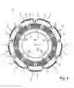
FIG. 1 is a top view of a stator of the invention according to an embodiment;
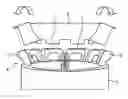
FIG. 2 is a view of a detail of the stator of the invention according to the embodiment;
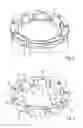
FIG. 3 is a view of a molded body of the stator of the invention according to the embodiment;
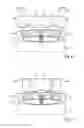
FIG. 4 is a view of a first variant of the production process of the stator of the invention according to the embodiment; and
FIG. 5 is a view of a second variant of the production process of the stator of the invention according to the embodiment.
DETAILED DESCRIPTION OF THE DRAWINGS
In the following, a stator 1 according to an embodiment will be described by means of FIGS. 1 to 3. FIGS. 4 and 5 illustrate two variants of the production process.
According to FIGS. 1 and 2, the stator 1 has a cylindrical stator body 2 made of metal. An axial direction 14 is defined corresponding to the cylindrical design of the stator body 2. The axial direction 14 corresponds to the position of a rotor shaft. A radial direction 15 extends perpendicularly to the axial direction 14.
The stator body 2 has several stator slots 3. Several first coils 4 and several second coils 6 are inserted into the stator slots 3. In the illustrated embodiment, nine first coils 4 and nine second coils 6 respectively are pulled into the stator body 2.
Nine first coil ends 5 and nine second coil ends 7 are constructed on each face of the stator body 2. A molded body 8 made of injection-molded plastic is inserted onto the face of the stator body 2. The molded body 8 separates the individual coil ends 5, 7 from one another. FIGS. 1 and 2 only show one face of the stator body 2. Actually, the molded body 8 is preferably used on both faces. The representation of nine coil ends respectively is to have no limiting effect. The process according to the invention and the molded body according to the invention respectively can also be used for a different number of coil ends.
In the production process of the stator 1, the first coils 2 are pulled into the stator slots 3 first. This is followed by the placing of the molded body 8 and therefore the inserting of the first coil ends 5 into the molded body 8. Subsequently, the pulling-in of the second coils 6 and the inserting of the second coil ends 7 into the molded body 8 takes place. For this purpose, FIG. 2 illustrates an intermediate step, in which the first coils 4 are already pulled in and the molded body 8 has been mounted.
FIG. 3 is a detailed view of the molded body 8. In the illustrated embodiment, a one-piece molded body 8 is used for each face of the stator body 2. Correspondingly, the molded body 8 is further developed in a ring shape. The molded body 8 has a separating wall 9. This separating wall 9 extends along the entire circumference of the stator body 2. The separating wall 9 separates all first coil ends 5 from all second coil ends 7. The separating wall 9 extends in the axial direction 14 and is therefore arranged coaxially to the cylindrical shape of the stator body 2.
Several partition walls 10 extend from the separating wall 8. Partitioning walls 10 particularly stand perpendicularly on the separating wall 9. The partition walls 10 extend in the radial direction 15 on the interior side and on the exterior side of the separating wall 9.
On the exterior side of the separating wall 9, the partition walls 10 are each used for the separation between two adjacent first coil ends 5. On the interior side, the partition walls 10 are each used for the separation of two adjacent second coil ends 7.
Nine first receiving devices 12 are constructed on the exterior side of the separating wall. The first receiving devices 12 are each situated between two partition walls 10. The first coil ends 5 are inserted into these receiving devices 12. Nine second receiving devices 13 are situated on the interior side of the separating wall 9. The second receiving devices 13 are also each situated between two partition walls 10. The two coil ends 7 are inserted into the second receiving devices 13.
The first and second receiving devices 12, 13 are each constructed as projections, which extend in the radial direction 15 away from the separating wall 9.
For the covering and insulation of the coil ends 5, 7, covering walls 11 are constructed at the molded body 8. The covering walls 11 stand perpendicularly on the separating wall 9 and perpendicularly with respect to the partition walls 10. In particular, one covering wall 11 is provided for each first receiving device 12.
FIGS. 4 and 5 show two different variants for producing the stator 1. According to FIGS. 4 and 5, the molded body 8 consists of one piece, is ring-shaped and closed.
As a result of a certain flexibility of the molded body 8 in FIG. 4, the latter can be folded toward the inside, so that it becomes possible to place the molded body 8 from the inside onto the first coil ends 5. After the placing of the molded body 8, the molded body 8 is folded toward the outside, so that the first coil ends 5 are inserted into the first receiving devices 12.
The molded body 8 in FIG. 5 is deformed for the mounting, so that the diameter of the molded body 8 is reduced. Also in the variant according to FIG. 5, the molded body 8 is placed from the inside onto the first coil ends 5, so that the first coil ends 5 are inserted into the first receiving devices 12.
As indicated in FIGS. 4 and 5, each coil 4, 6 preferably consists of two individual coils connected in series. A separate stator slot 3 is provided for each individual coil. In the illustrated embodiment, there are therefore four stator slots 3 for each coil 4, 6.
LIST OF REFERENCE NUMBERS
1 Stator
2 Stator body
3 Stator slots
4 First coils
5 First coil ends
6 Second coils
7 Second coil ends
8 Molded body
9 Separating wall
10 Partition walls
11 Covering walls
12 First receiving devices
13 Second receiving devices
14 Axial direction
15 Radial direction
The foregoing disclosure has been set forth merely to illustrate the invention and is not intended to be limiting. Since modifications of the disclosed embodiments incorporating the spirit and substance of the invention may occur to persons skilled in the art, the invention should be construed to include everything within the scope of the appended claims and equivalents thereof.
Claims
What is claimed is:1. A method for producing a stator for an electric machine, comprising the acts of:
providing a cylindrical stator body having several stator slots,
inserting at least one first coil in the stator slots, each of the at least one first coil having a first coil end on at least one face of the stator body; and
inserting, following said inserting at least one first coil in the stator slots, the first coil end in at least one molded body for electrically insulating the first coil end.
2. The method according to claim 1, wherein a plurality of first coils are inserted into the stator slots, and subsequently the first coil ends are inserted in the at least one molded body.
3. The method according to claim 1, wherein, after the inserting of the first coil ends in the at least one molded body, the method comprises inserting second coils into the stator slots, the second coils having second coil ends and the second coil ends being inserted into the molded body.
4. The method according to claim 2, wherein, after the inserting of the first coil ends in the at least one molded body, the method comprises inserting second coils into the stator slots, the second coils having second coil ends and the second coil ends being inserted into the molded body.
5. The method according to claim 3, wherein the second coils are arranged in the cylindrical stator body within the first coils.
6. The method according to claim 4, wherein the second coils are arranged in the cylindrical stator body within the first coils.
7. The method according to claim 3, wherein the first coil ends and second coil ends are inserted in the same molded body.
8. The method according to claim 5, wherein the first coil ends and second coil ends are inserted in the same molded body.
9. The method according to claim 3, wherein at least one of the first coils and second coils are wound outside the stator body and are subsequently pulled into the stator slots.
10. The method according to claim 5, wherein at least one of the first coils and second coils are wound outside the stator body and are subsequently pulled into the stator slots.
11. The method according to claim 7, wherein at least one of the first coils and second coils are wound outside the stator body and are subsequently pulled into the stator slots.
12. The method according to claim 2, wherein the coil ends are pressed together with the molded body.
13. The method according to claim 1, wherein the molded body comprises an injection-molded plastic.
14. A stator for an electric machine, the stator comprising:
a cylindrical stator body having several stator slots;
at least one first coil inserted into the stator slots, each of the at least one first coil having a first coil end on at least one face of the stator body;
at least one second coil inserted into the stator slots, the second coil having a second coil end on the at least one face of the stator body, and the second coil being arranged in the cylindrical stator body within the first coil; and
at least one molded body for the electric insulation of the coil ends, the molded body comprising a separating wall arranged between the first coil end and the second coil end.
15. The stator according to claim 14, wherein the separating wall completely covers the coil ends.
16. The stator according to claim 9, wherein the separating wall of the at least one molded body is arranged between several first coil ends and several second coil ends.
17. The stator according to claim 10, wherein the separating wall of the at least one molded body is arranged between several first coil ends and several second coil ends.
18. The stator according to claim 14, wherein the at least one molded body has at least one partition wall arranged between two adjacent first coil ends or between two adjacent second coil ends.
19. The stator according to claim 16, wherein the at least one molded body has at least one partition wall arranged between two adjacent first coil ends or between two adjacent second coil ends.
20. A molded body for electrically insulating coil ends arranged in a stator of an electric machine, wherein the stator comprises a cylindrical stator body having a plurality of stator slots, at least one first coil inserted into the stator slots, the first coil having a first coil end on at least one face of the stator body, and at least one second coil inserted into the stator slots, the second coil having a second coil end on the at least one face of the stator body, wherein the second coil is arranged in the cylindrical stator body within the first coil, and wherein the molded body comprises a separating wall which, in an installed condition of the molded body, is arranged between the first coil end and the second coil end.
Images & Drawings included:
Sources:
- United States Patent and Trademark Office - verify current appl. status at the USPTO↗
Similar patent applications:
- » 20140001914
STATOR FOR AN ELECTRIC MOTOR AND METHOD FOR PRODUCING A STATOR FOR AN ELECTRIC MOTOR - » 20150084447
Stator including a bracket, electric motor including a stator, and method of producing an electric motor - » 20210273535
Stator device, electric flat motor and method for producing a stator device - » 20220006343
Stator for an electric machine, electric machine, motor vehicle, method for producing a stator - » 20210399606
Electric motor with overmolding connecting electronics and/or terminal housing and stator to each other and method for producing an electric motor - » 20220190668
Stator of a coolant drive, electric motor, refrigerant drive and method of producing a stator - » 20190181711
Method for producing an electric motor with stator having step-shaped stator teeth - » 20110278980
Stator coil production method and electric motor equipped with stator coil produced by the same - » 20180166932
Stator for a multiphase electric motor, method for producing a coil winding, and electric motor for a handheld tool - » 20160226351
Method for producing a stator for an electric motor
Recent applications in this class:
- » 20250183746 2025-06-05
INSULATION RING, STATOR AND METHOD FOR PRODUCING A STATOR - » 20250112515 2025-04-03
STATOR FOR ROTATING ELECTRIC MACHINE, AND INSULATOR - » 20250030295 2025-01-23
ROTATING ELECTRICAL MACHINE WIRING COMPONENT AND ROTATING ELECTRICAL MACHINE WIRING COMPONENT MANUFACTURING METHOD - » 20240364169 2024-10-31
STATOR FOR AN ELECTRIC MACHINE, METHOD FOR PRODUCING A STATOR, ELECTRIC MACHINE AND VEHICLE - » 20240097518 2024-03-21
STATOR, METHOD FOR MANUFACTURING STATOR, AND BRUSHLESS MOTOR - » 20230291265 2023-09-14
Motor stator having electrical insulators with overlapping parts - » 20230253851 2023-08-10
Electric Machine for a Motor Vehicle, Use of Such an Electric Machine, and Motor Vehicle - » 20230163653 2023-05-25
Motor - » 20230155438 2023-05-18
STATOR, MOTOR INCLUDING THE SAME AND STATOR ASSEMBLING METHOD - » 20230026208 2023-01-26
STATOR AND METHOD OF MANUFACTURING SAME
Recent applications for this Assignee:
- » 20250236179 2025-07-24
METHOD FOR OPERATING A BRAKE CONTROL SYSTEM, BRAKE CONTROL SYSTEM, COMPUTER PROGRAM, AND COMPUTER-READABLE STORAGE MEDIUM - » 20250109792 2025-04-03
Mounting assembly for a coupler mechanism of a motor vehicle - » 20250077042 2025-03-06
Method for increasing safety during the operation of a device - » 20250042351 2025-02-06
Arrangement for Holding a Sidewall Element on a Bodyshell Part of a Vehicle, Bracket and Vehicle - » 20250026428 2025-01-23
Handlebar Assembly for a Motor Vehicle, and Motor Vehicle Having a Handlebar Assembly of This Kind - » 20250020305 2025-01-16
Decorative element for a motor vehicle, and production method for a decorative element - » 20250001843 2025-01-02
Motor Vehicle With a Side Door - » 20240426445 2024-12-26
Motor Vehicle Lighting Module - » 20240383554 2024-11-21
Leaning vehicle - » 20240383416 2024-11-21
Motor vehicle having a plurality of control devices which provide different vehicle functions in the motor vehicle and method for configuring the control devices and control device