Low-profile plug with cam and flexible circuit board
US20150249297A1
2015-09-03
14/195,823
2014-03-03
✅ Patent granted
US 9,357,654 B2
2016-05-31
-
-
Abdullah Riyami | Thang Nguyen
Kilpatrick Townsend & Stockton LLP
2034-05-08
Abstract:
A cable assembly including a connector insert to fit in a connector receptacle in an electronic device, where a back surface of the connector insert is substantially flush with an outside of an enclosure for the electronic device. One example may provide a cable assembly that includes a connector insert formed by wrapping a flexible circuit board at least partially around a housing. The flexible circuit board may be routed against an underside of the electronic device such that it does not obstruct a user, consume space in a display area, or have an undesirable appearance.
Inventors:
- Min Chul Kim 46 🇺🇸 Santa Clara, CA, United States
- Paul Yuan 8 🇺🇸 San Jose, CA, United States
- Nathan Ng 2 🇺🇸 Fremont, CA, United States
Assignee:
- APPLE INC. 35,014 🇺🇸 Cupertino, CA, United States
Applicant:
Interested in similar patents?
Get notified when new applications in this technology area are published.
Classification:
H01R13/62905 » CPC further
Details of coupling devices of the kinds covered by groups or -; Means for facilitating engagement or disengagement of coupling parts or for holding them in engagement; Additional means for facilitating engagement or disengagement of coupling parts, e.g. aligning or guiding means, levers, gas pressure electrical locking indicators, manufacturing tolerances comprising a camming member
H01R12/61 » CPC main
Structural associations of a plurality of mutually-insulated electrical connecting elements, specially adapted for printed circuits, e.g. printed circuit boards [PCBs], flat or ribbon cables, or like generally planar structures, e.g. terminal strips, terminal blocks; Coupling devices specially adapted for printed circuits, flat or ribbon cables, or like generally planar structures; Terminals specially adapted for contact with, or insertion into, printed circuits, flat or ribbon cables, or like generally planar structures; Fixed connections for flexible printed circuits, flat or ribbon cables or like structures connecting to flexible printed circuits, flat or ribbon cables or like structures
H01R13/629 IPC
Details of coupling devices of the kinds covered by groups or -; Means for facilitating engagement or disengagement of coupling parts or for holding them in engagement Additional means for facilitating engagement or disengagement of coupling parts, e.g. aligning or guiding means, levers, gas pressure electrical locking indicators, manufacturing tolerances
H05K3/303 » CPC main
Apparatus or processes for manufacturing printed circuits; Assembling printed circuits with electric components, e.g. with resistor Surface mounted components, e.g. affixing before soldering, aligning means, spacing means
H05K3/303 » CPC main
Apparatus or processes for manufacturing printed circuits; Assembling printed circuits with electric components, e.g. with resistor Surface mounted components, e.g. affixing before soldering, aligning means, spacing means
H05K3/30 IPC
Apparatus or processes for manufacturing printed circuits Assembling printed circuits with electric components, e.g. with resistor
H05K3/30 IPC
Apparatus or processes for manufacturing printed circuits Assembling printed circuits with electric components, e.g. with resistor
H05K1/189 » CPC further
Printed circuits; Printed circuits structurally associated with non-printed electric components characterised by the use of a flexible or folded printed circuit
H05K1/189 » CPC further
Printed circuits; Printed circuits structurally associated with non-printed electric components characterised by the use of a flexible or folded printed circuit
H05K2201/056 » CPC further
Indexing scheme relating to printed circuits covered by; Flexible printed circuits [FPCs] Folded around rigid support or component
H05K2201/056 » CPC further
Indexing scheme relating to printed circuits covered by; Flexible printed circuits [FPCs] Folded around rigid support or component
H05K2201/10189 » CPC further
Indexing scheme relating to printed circuits covered by; Details of components or other objects attached to or integrated in a printed circuit board; Types of components Non-printed connector
H05K2201/10189 » CPC further
Indexing scheme relating to printed circuits covered by; Details of components or other objects attached to or integrated in a printed circuit board; Types of components Non-printed connector
Y10T29/4913 » CPC further
Metal working; Method of mechanical manufacture; Electrical device making; Conductor or circuit manufacturing; On flat or curved insulated base, e.g., printed circuit, etc. Assembling to base an electrical component, e.g., capacitor, etc.
H01R3/00 IPC
Electrically-conductive connections not otherwise provided for
H01R31/06 » CPC further
Coupling parts supported only by co-operation with counterpart Intermediate parts for linking two coupling parts, e.g. adapter
H05K1/18 IPC
Printed circuits Printed circuits structurally associated with non-printed electric components
H05K1/18 IPC
Printed circuits Printed circuits structurally associated with non-printed electric components
H01R24/62 » CPC further
Two-part coupling devices, or either of their cooperating parts, characterised by their overall structure; Contacts spaced along planar side wall transverse to longitudinal axis of engagement Sliding engagements with one side only, e.g. modular jack coupling devices
Description
BACKGROUND
The amount of data transferred between electronic devices has grown tremendously the last several years. Large amounts of audio, streaming video, text, and other types of data content are now regularly transferred among desktop and portable computers, media devices, handheld media devices, displays, storage devices, and other types of electronic devices. Power supply voltages and ground may be transferred with this data.
Power and data may be conveyed over cables that may include wire conductors, fiber optic cables, or some combination of these or other conductors. Cable assemblies may include a connector insert at one or both ends of a cable, though cable assemblies may be connected or tethered to an electronic device in a dedicated manner. The connector inserts may be inserted into receptacles in the communicating electronic devices.
Many of these electronic devices are now being used in retail or other environments where customers and others interact directly with them. These devices may include touch or other types of screens that provide information about various items, products, or services. These screens may also allow users to explore databases to find further information, to request help, to place orders, or to interact in other ways.
Again, conventional cable assemblies include a connector insert at an end of a cable. The connector insert includes an insert portion to fit in a connector receptacle in an electronic device. A housing of the connector insert attaches to the insert portion and does not fit into the connector receptacle, but rather extends orthogonally to an exterior surface of the electronic device. The cable may extend from the housing, also in a direction orthogonal to the exterior surface of the electronic device.
While this housing may be very convenient in that is allows a user to easily insert and remove the connector insert, it may obstruct a user interacting with the electronic device. It may also consume space in a display area and have an undesirable appearance.
Thus, what is needed are cable assemblies including connector inserts that do not obstruct a user, do not consume space in a display area, and do not have an undesirable appearance.
SUMMARY
Accordingly, embodiments of the present invention may provide cable assemblies that do not obstruct a user, do not consume space in a display area, and do not have an undesirable appearance. An illustrative embodiment of the present invention may provide a cable assembly including a connector insert to fit in a connector receptacle in an electronic device, where a back surface of the connector insert is substantially flush with an outside of an enclosure for the electronic device. One such illustrative embodiment of the present invention may provide a cable assembly that includes a flexible circuit board at least partially wrapped around a cam or housing. The flexible circuit board may be routed against an underside of the electronic device such that it does not obstruct a user, does not consume space in a display area, and does not have an undesirable appearance.
An illustrative embodiment of the present invention may include flexible cable at least partially wrapped around a cam or other housing. The flexible cable may be a flexible circuit board, ribbon connector, or other flexible cable. The flexible cable may be substantially flat to aid in keeping the cable out of sight of a user. The flexible cable may have an end portion, with a number of contacts printed or otherwise formed on a first side of the end portion of the flexible cable. The contacts may be electrically connected to conductors in the flexible cable.
One or more circuits or components may be attached to a second side of the flexible cable. In this way, the flexible cable may provide part of an enclosure for the circuits or components. These circuits may include active devices, passive components, integrated circuits, relays, switches, microelectromechanical devices (MEMs), or other electronic or mechanical components. These components may include circuits for power, identification, authorization, theft-prevention, and other functions. The components may be electrically connected to one or more conductors in the flexible cable and the contacts.
These components may be enclosed between the flexible cable and a housing, such as a cam or other type of housing. The housing may be metallic, though in various embodiments of the present invention it may be plastic, resin, ceramic, or other material or combination of these and other materials. The housing may have a first recess and the components may be located in the first recess. The housing may have a second recess and the end portion of the flexible cable may be located in the second recess. The housing or cam may help to enclose and protect the components, act as a plug head, and have a rear portion that conforms to an outside of a device enclosure.
The end portion of the flexible cable may be secured to the housing in the second recess. The end portion may be glued, taped, fixed with adhesive, or otherwise secured in place. The flexible cable may be wrapped at least partially around the housing or cam. This may allow contacts to be on a first side of the flexible cable and may allow the flexible cable to contact and enclose the components and exit the electronic device along its underside.
Again, the housing may have a back end arranged to be substantially flush with an outside of an enclosure for the electronic device. This, combined with the use of a flexible cable that may be discreetly routed, may provide a cable assembly that is unobtrusive, does not consume display area, and does not have an undesirable appearance. When a cable insert according to an embodiment of the present invention is inserted in an electronic device, the cable assembly may provide a connector insert and flexible cable that are not readily viewable by a user while that user is looking at a screen of the electronic device.
Contacts on the end portion of the flexible cable may engage or mate with connectors in the receptacle of the electronic device. Specifically, the housing may be arranged such that the contacts on the first side of the end portion of the flexible cable mate with contacts in the connector receptacle on the electronic device. These connections may be used to convey data, power, startup or configuration information, or other types of signals between the electronic device and one or more other electronic devices or networks.
While these cables may be useful in retail environments where they may rarely be disconnected, it may be desirable to disconnect them on occasion. It may be desirable that these cables not be removed by someone simply grabbing the flexible cable, as this may damage the cable assembly. Accordingly, embodiments of the present invention may include a pull tab for use in disconnecting and removing the cable assembly. This pull tab may be fixed using glue, tape, or adhesive, or otherwise attached to the first side of the flexible cable.
An illustrative embodiment of the present invention may provide a method of forming a cable assembly. This method may include forming a plurality of contacts on a first side at a first end portion of a flexible circuit board. A first component may be attached to a second side of a flexible circuit board. A housing may be aligned over the first component such that the first component fits in a first recess of the housing. A flexible circuit board may be at least partially wrapped around the housing. A pull tab may be attached to the first side of the flexible circuit board to enable the removal of the housing when it is inserted in a receptacle of an electronic device.
Embodiments of the present invention may be used in connector inserts and receptacles for cables that may connect to various types of devices, such as portable computing devices, tablets, desktop computers, laptops, all-in-one computers, cell phones, smart phones, media phones, storage devices, portable media players, navigation systems, monitors, power supplies, adapters, and chargers, and other devices. These connector inserts may provide pathways for signals and power compliant with various standards such as Universal Serial Bus (USB), a High-Definition Multimedia Interface (HDMI), Digital Visual Interface (DVI), power, Ethernet, DisplayPort, Thunderbolt, Lightning and other types of standard and non-standard interfaces.
Various embodiments of the present invention may incorporate one or more of these and the other features described herein. A better understanding of the nature and advantages of the present invention may be gained by reference to the following detailed description and the accompanying drawings.
BRIEF DESCRIPTION OF THE DRAWINGS
FIG. 1 illustrates a cable assembly according to an embodiment of the present invention;
FIG. 2 illustrates a cable assembly according to an embodiment of the present invention;
FIG. 3 illustrates a cable assembly inserted into an electronic device in accordance with an embodiment of the present invention;
FIG. 4 illustrates a flexible cable according to an embodiment of the present invention;
FIG. 5 illustrates an intermediate step in the manufacturing of a cable assembly according to an embodiment of the present invention;
FIG. 6 illustrates a cam or housing 210 according to an embodiment of the present invention;
FIG. 7 illustrates a completed cable assembly according to an embodiment of the present invention;
FIG. 8 illustrates a close-up view of a connector insert portion according to an embodiment of the present invention; and
FIG. 9 illustrates another close-up view of a connector insert portion according to an embodiment of the present invention.
DESCRIPTION OF ILLUSTRATIVE EMBODIMENTS
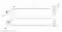
FIG. 1 illustrates a cable assembly according to an embodiment of the present invention. This figure, as with the other included figures, is shown for illustrative purposes and does not limit either the possible embodiments of the present invention or the claims.
This figure includes a cable assembly including connector insert portion 110 and flexible cable 120. Connector insert portion 110 may be configured to be inserted in receptacle 112 and may have a back that is arranged to fit approximately flush with an outside of an enclosure of electronic device 140. Flexible cable 120 may include a wider portion 122. To assist in removal of connector insert portion 110, a pull tab 130 may be included. Connector insert portion 110 may be removed by pulling on pull tab 130 in a direction approximately orthogonal to a surface of the device enclosure for the electronic device 140.
Again, connector insert portion 110 may be arranged to be substantially flush with a surface of device enclosure 140. Flexible cable 120 may be routed underneath the electronic device and away from connector insert portion 110. Pull tab 130 may similarly be folded underneath the electronic device. This may provide a cable assembly that is not visible to a user who is viewing a screen on the electronic device. (In this figure, the screen may be facing downward towards a surface on which the electronic device is resting.)
Traces or conductors in flexible cable 120 may attach to contacts on connector insert portion 110. These contacts may mate or form electrical connections with contacts in the connector receptacle 112. In this way, power, data, and other signals may be transferred between the electronic device and one or more other electronic devices.
In this specific example, flexible cable 120 may be a flexible circuit board, though in other embodiments of the present invention it may be a ribbon cable or other type of flexible cable.
FIG. 2 illustrates a cable assembly according to an embodiment of the present invention. In this example, flexible cable 120 may be wrapped at least partially around a cam or housing 210. Cam or housing 210 may include a first recess. One or more electronic components 220 may be located in this recess. These components may include active devices, passive components, integrated circuits, relays, switches, microelectromechanical devices (MEMs), or other electronic or mechanical components. These components may include circuits for power, identification, authorization, theft-prevention, and other functions.
One or more contacts 124 may be printed or otherwise formed on flexible cable 120. These contacts may be printed on a first side of a first end portion of flexible cable 220. The end portion of flexible cable 120 may fit in a second recess in housing 210. The first end portion of flexible cable 120 may be glued, attached with adhesive or tape, or otherwise fixed to cam or housing 210. Pull tab 130 may be attached to insert portion 110. For example, pull tab 130 may be glued, fixed with adhesive or tape, or otherwise attached to a first surface of flexible cable 120.
Again, when connector insert portion 110 is inserted into a receptacle, contacts 124 may mate with corresponding contacts in a connector receptacle. Also, flexible cable 120 may be routed away and underneath the electronic device 140 such that the cable assembly is not visible to a user viewing a screen on the electronic device. An example is shown in the following figure.
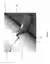
FIG. 3 illustrates a cable assembly inserted into an electronic device in accordance with an embodiment of the present invention. Again, connector insert portion 110 may include one or more electrical components 220. These electrical components 220 may be housed in a recess in housing or cam 210. Flexible cable 120 may be at least partially wrapped around cam or housing 210. Pull tab 130 may be included to assist in the removal of connector insert portion 110 from electronic device 140. Again, a rear of housing 210 may be arranged to fit substantially flush with an outside surface of an enclosure for electronic device 140.
One or more contacts 124 formed on flexible cable 120 may mate with corresponding contacts 324 in the connector receptacle 112. These connections may convey power, data, startup or configuration information, or other signals between this electronic device 140 and one or more other electronic devices. More specifically, contacts 124 may electrically connect to contacts at a distant end of flexible cable 120. Contacts 124 and distant contacts (not shown) may electrically connect to each other or to components 220. An example of one flexible cable 120 is shown in the following figure.
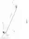
FIG. 4 illustrates a flexible cable according to an embodiment of the present invention. This flexible cable 120 may include a number of contacts 124 on an end portion of flexible cable 120. Pull tab 130 may also be attached to flexible cable 120. Distant end portion 128 may include a number of contacts 410, 412, 414, and 416. These contacts may convey data and power between electronic device 140 and one or other electronic devices. In a specific embodiment of the present invention, contacts 410 may be a D− contact and contact 412 may be a D+ contact. These contacts may convey a Universal Serial Bus or other differential signal. Contact 414 may be a VBUS contact, while contact 416 may be a ground contact. This second set of contacts may supply power to electronic device 140. A second side of flexible cable 120 may include a contact area 420, where one or more components may be attached. Traces may connect these components to one or more contacts 124, as well as one or more contacts on distant end portion 128.
Connector assemblies consistent with embodiments of the present invention may be manufactured in various ways. An example is shown in the following figure.
FIG. 5 illustrates an intermediate step in the manufacturing of a cable assembly according to an embodiment of the present invention. One or more contacts 124 may be formed on an end portion of flexible cable 120. Pull tab 130 may be attached to the top surface of flexible cable 120. One or more electrical components 220 may be attached to a second side of flexible cable 120. A cam or housing may be placed over electrical components 220. Flexible cable 120 may be at least partially wrapped around this cam or housing. An example of such a cam or housing is shown in the following figure.
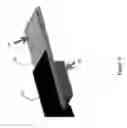
FIG. 6 illustrates a cam or housing 210 according to an embodiment of the present invention. Cam or housing 220 may include a first recess 610. One or more electrical components 220 may be located in first recess 610. In one example, components 220 may be sealed in a structure that is arranged to fit in first recess 610. This may provide improved heat dissipation for components 220. Cam or housing 210 may protect electrical components 220 and provide a mechanical support for flexible cable 120. Cam or housing 210 may include a second recess 620. An end portion of flexible cable 120 supporting contacts 124 may be located in second recess 620. This end portion may be glued, fixed with adhesive or tape, or otherwise secured to second recess 620. In other embodiments of the present invention, a lip or edge around the recess 620 may be used to secure the flexible cable 120 in place. Cam or housing 210 may further include side indentations 630, which may be grasped by a user during insertion into electronic device.
FIG. 7 illustrates a completed cable assembly according to an embodiment of the present invention. Again, flexible cable 120 may be at least partially wrapped around housing 210 to form connector insert portion 110. Pull tab 130 may be attached to connector insert portion 110 to assist in the removal of connector insert portion 110 from an electronic device. An end portion of flexible cable 120 may support a number of contacts that may be electrically connected to contacts 124 on connector insert portion 110 and to one or more electrical components 220 inside housing 210.
FIG. 8 illustrates a close-up view of a connector insert portion according to an embodiment of the present invention. Again, a number of contacts 124 may be located on an end portion of flexible cable 120. Flexible cable 120 may include a wider portion 122. Flexible cable 120 may be at least partially wrapped around housing 210. A pull tab 130 may be included.
FIG. 9 illustrates another close-up view of a connector insert portion according to an embodiment of the present invention. Again, connector insert portion 110 may include housing 210. Pull tab 130 may also be included.
The above description of embodiments of the invention has been presented for the purposes of illustration and description. It is not intended to be exhaustive or to limit the invention to the precise form described, and many modifications and variations are possible in light of the teaching above. The embodiments were chosen and described in order to best explain the principles of the invention and its practical applications to thereby enable others skilled in the art to best utilize the invention in various embodiments and with various modifications as are suited to the particular use contemplated. Thus, it will be appreciated that the invention is intended to cover all modifications and equivalents within the scope of the following claims.
Claims
What is claimed is:1. A connector insert comprising:
a housing;
a flexible circuit board at least partially wrapped around the housing; and
a plurality of contacts formed on the flexible circuit board.
2. The connector insert of claim 1 wherein the housing is metallic.
3. The connector insert of claim 1 wherein the housing comprises a first recess, wherein at least one component attached to the flexible circuit board is located in the first recess.
4. The connector insert of claim 3 wherein the plurality of contacts are located on a first end portion of the flexible circuit board.
5. The connector insert of claim 4 wherein the housing includes a second recess and the first end portion of the flexible circuit board is located in the second recess.
6. The connector insert of claim 5 further comprising a pull tab attached to the flexible circuit board.
7. The connector insert of claim 1 further comprising a pull tab attached to the flexible circuit board.
8. The connector insert of claim 1 further comprising a pull tab attached to the connector insert.
9. A method of manufacturing a connector insert comprising:
forming a plurality of contacts on a first side at a first end portion of a flexible circuit board;
attaching a first component to a second side of a flexible circuit board;
aligning a housing over the first component such that the first component fits in a first recess of the housing; and
at least partially wrapping the flexible circuit board around the housing.
10. The method of claim 9 further comprising:
attaching a pull tab to the first side of the flexible circuit board.
11. The method of claim 9 wherein the first end portion of the flexible circuit board fits in a second recess in the housing.
12. The method of claim 9 wherein the housing is metallic.
13. A cable assembly including a connector insert arranged to have a low-profile when inserted into an electronic device, the cable assembly comprising:
a housing formed to fit in a receptacle in the electronic device and having a back surface arranged to be substantially flush with an outside surface of an enclosure for the electronic device;
a flexible cable at least partially wrapped around the housing; and
a plurality of contacts formed on the flexible cable and arranged to mate with contacts in the receptacle.
14. The cable assembly of claim 13 wherein the housing is metallic.
15. The cable assembly of claim 13 wherein the housing comprises a first recess, and wherein at least one component attached to the flexible cable is located in the first recess.
16. The cable assembly of claim 15 wherein the plurality of contacts are located on a first end portion of the flexible cable.
17. The cable assembly of claim 16 wherein the housing includes a second recess and the first end portion of the flexible cable is located in the second recess.
18. The cable assembly of claim 17 further comprising a pull tab attached to the flexible cable.
19. The cable assembly of claim 13 further comprising a pull tab attached to the flexible cable.
20. The cable assembly of claim 13 further comprising a pull tab attached to the connector insert.
21. The cable assembly of claim 13 wherein the flexible cable is a flexible circuit board.
Images & Drawings included:


Sources:
- United States Patent and Trademark Office - verify current appl. status at the USPTO↗
Recent applications in this class:
- » 20240243497 2024-07-18
CONNECTION STRUCTURE FOR CONNECTING FLAT CABLE AND TERMINAL FITTING - » 20240235072 2024-07-11
FLEXIBLE PRINTED CIRCUIT CONNECTION STRUCTURE - » 20240136740 2024-04-25
FLEXIBLE PRINTED CIRCUIT CONNECTION STRUCTURE - » 20230045382 2023-02-09
Electrical connector for attachment to textile - » 20220399662 2022-12-15
System for assembling cables in a connector and method - » 20220399661 2022-12-15
Flexible circuit board, touch display module and touch display apparatus - » 20220085527 2022-03-17
Butt joint flex circuit board interconnection - » 20210210878 2021-07-08
Flexible printed circuits marked with connections to vehicle circuits - » 20210057835 2021-02-25
Electrical connector with flexible circuit and stiffener - » 20210036445 2021-02-04
Structure for connecting flexible flat cables
Recent applications for this Assignee:
- » 20250294600 2025-09-18
LOWER LAYER CONTROL SIGNAL FOR DOWNLINK POSITIONING REFERENCE SIGNAL - » 20250294316 2025-09-18
TECHNIQUES FOR SYNCHRONIZING ULTRA-WIDE BAND COMMUNICATIONS - » 20250294255 2025-09-18
Optical Image Stabilization with Voice Coil Motor for Moving Image Sensor - » 20250293825 2025-09-18
IDENTIFYING VICTIM AND AGGRESSOR USER EQUIPMENT - » 20250293811 2025-09-18
HYBRID AUTOMATIC REPEAT REQUEST DISABLEMENT - » 20250291890 2025-09-18
UNLOCKING A DEVICE - » 20250291232 2025-09-18
CAMERA WITH FOLDED OPTICS HAVING MOVEABLE LENS - » 20250287250 2025-09-11
PARALLEL BEAM MANAGEMENT IN NEW BAND COMBINATIONS - » 20250286783 2025-09-11
ACTIVE BANDWIDTH PARTS SUPPORT FOR FRAGMENTED CARRIERS - » 20250286621 2025-09-11
COMMUNICATION DEVICES AND METHODS FOR HIGH-THROUGHPUT, LOW-POWER SIGNALING