SOLAR PANEL INTERFACE WITH AIR CONDITIONING AND/OR HEAT PUMP UNIT SYSTEM
US20150267946A1
2015-09-24
14/660,540
2015-03-17
Abstract:
A solar hybrid system having a solar panel connected to an air conditioning and heat pump unit. The system having a tracking system for the solar panel and heat pump bypass circuit for the air conditioning and heat pump units.
Inventors:
- William R. Lowstuter, JR. 2 🇺🇸 Golden, CO, United States
- Richard A. Cooley 1 🇺🇸 Phoenix, AZ, United States
- Michael Weinberger 1 🇺🇸 Oro Valley, AZ, United States
- Robbie Ashby 1 🇺🇸 Phoenix, AZ, United States
Interested in similar patents?
Get notified when new applications in this technology area are published.
Classification:
F25B27/005 » CPC main
Machines, plants or systems, using particular sources of energy using solar energy in compression type systems
F25B27/00 IPC
Machines, plants or systems, using particular sources of energy
Description
CROSS REFERENCE TO RELATED APPLICATION
This application claims the benefit of U.S. Provisional Application No. 61/954,945 filed Mar. 18, 2014.
BACKGROUND OF THE INVENTION
The present invention is directed to an air conditioning and/or heat pump system, and more particularly to a system that combines a solar panel with an air conditioning and heat system.
Solar hybrid systems are known in the art. Typically, these systems utilize evacuated tubes and flat panels. While useful, these systems have many deficiencies. For one, because the solar panel does not track with the movement of the sun, the systems are less efficient in transferring radiant energy to refrigerant within the system. Further, these systems lack controls to produce optimum results. Therefore, a need exists in the art for a system that addresses these problems.
An objective of the present invention is to provide a solar hybrid system that is more efficient and controls the amount of thermal energy generated though modulation of the solar tracking panel.
Another objective is to provide a solar hybrid system having a heat pump by pass circuit.
A still further objective is to provide a solar hybrid system capable of a retrofit.
These and other objectives will be apparent to one of ordinary skill in the art based upon the following written description, drawings, and claims.
BRIEF SUMMARY OF THE INVENTION
A solar hybrid system having a solar panel connected to an air conditioning and heat system and/or refrigeration system. Preferably, the solar panel is capable of pivotal movement to track with the sun as it moves throughout the day.
The air conditioning heat system includes a compressor, condenser, an evaporator and a heat pump bypass circuit, and the refrigeration system includes a compressor, condenser, and an evaporator. A computer is connected to the system and its parts as well as a base station and a building computer.
BRIEF DESCRIPTION OF THE DRAWINGS
FIG. 1 is a schematic view of a solar panel air conditioning/refrigeration system;
FIG. 2 is a schematic view of a solar panel air conditioning/heat system;
FIG. 3 is a schematic view of a heat pump refrigerant piping circuit;
FIG. 4 is an electrical schematic view of a heat pump bypass;
FIG. 5 is a schematic view of a computer;
FIG. 6 is a schematic of a solar panel HVAC system; and
FIG. 7 is a schematic of a solar panel HVAC system.
DETAILED DESCRIPTION OF THE PREFERRED EMBODIMENT
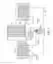
Referring to the Figures, a solar panel air conditioning/heat system 10 has a compressor 12 connected to a solar panel 14 which is connected to a condenser 16 by a fluid conduit 18. The condenser 16 is connected to an evaporator 20 that is also connected to the compressor 12 by fluid conduit 18 to form a closed circuit. A thermal expansion valve 22 is connected to the fluid conduit 18 between the condenser 16 and the evaporator 20. In an alternative embodiment a second thermal expansion valve 24 is connected to the fluid conduit 18 between the evaporator 20 and the condenser 16 along with one or more bypass valves 26.
The compressor 12 is of any type including but not limited to a single speed, single stage, multi-stage, variable speed, variable flow rate, variable capacity high efficiency or the like. Preferably the system 10 has at least one compressor ranging in size from 1 ton/12,000 British Thermal Units (BTU) to large commercial and industrial applications. The solar panel 14 also is of any type and preferred is an enclosed solar collector of U.S. Pat. No. 7,665,459 to Lowstuter, Jr. incorporated by reference herein in its entirety. As an example the solar panel 14 includes a plurality of elongated parabolic reflectors 28 mounted within a glass-topped enclosure 30 and mounted to a building structure for pivotal movement such that each reflector 28 is incrementally pivoted throughout the course of a day to remain substantially perpendicular to the sun. The incremental pivotal movement is caused by a motor energized from a solar switch having light sensing devices that also pivot throughout the day so that in one position of the switch, no electricity is being generated and transferred to the motor, but in a second position the switch receives solar radiation and energizes the motor to again incrementally pivot each reflector along the with the solar switch. The incremental pivoting of the reflectors 28 provides optimal collection of solar radiation which is used to heat working fluid/gas carried by tubes positioned at the axis of generation of the parabolic reflectors 28 and/or strips of solar cell material so that electricity can be generated alone, working fluid/gas heated alone, or working fluid/gas heated and electricity generated simultaneously.
A light sensing system controls a brushless stepper motor which tracks the sun east to west as it crosses the sky, allowing the parabolic mirror array to stay focused throughout the day. This ability to track the sun's path allows the solar panel 14 to increase thermal efficiency up to 20% when compared to evacuated tube and flat panels.
In operation, refrigerant (working fluid/gas) leaves the compressor 12 after heat and pressure are increased. The refrigerant is of any type of working fluid such as water, glycol, gasses and other materials. The refrigerant then proceeds into the solar thermal panel 14 where additional heat and pressure are added to the refrigerant using radiant energy from the sun. The refrigerant is then delivered as a higher-temperature and higher-pressurized gas to the condenser(s) 16 within the solar hybrid air conditioning system 10. This process adds the heat and pressure to the refrigerant within the solar panel 14 allowing the compressor 12 to operate in a lower stage, state, range or capacity, thus reducing the electrical energy needed to operate the compressor at full capacity.
Custom Mounting
In one embodiment the system includes a temperature sensing system 31 to monitor and control the heat added to the system's refrigerant. This allows the system to constantly maintain refrigerant temperatures and pressures in their optimum range. The temperature sensing system 31 includes a plurality of sensors 32 that measure inlet manifold temperature, outlet discharge temperature, motor enclosure temperature, panel interior temperature, manifold tube temperature, and outside ambient air temperature. The sensors 32 transmit temperature information to a computer 34 at a base station 36. These temperature inputs, that preferably are between 4-20 milliAmps (mA) or 0-5 Volts of Direct Current (VCD), are used to determine current flow, voltage and power from the photovoltaic cells of the solar panel 14. The solar panel also has sensors 36 that provide digital inputs to the computer 34 related to water flow, wind direction, anemometer and the like.
Additional information transmitted from the solar panel 14 to the computer includes the on east limit, on west limit, solar insolation value from the photodiodes, the time from the last incremental move to make sure the solar panel 14 is not stuck, various pulses and counts, and air conditioning mode information such as day, night, cooling, heating and ventilation, and the information will also allow the solar panel system 10 to modulate the parabolas relative position to the sun, in order to maintain, increase, or decrease the amount of solar thermal energy being generated by the solar panel.
Based on the transmitted information, the computer 34 will activate the bypass valve when the solar panel is not tracking, operate valves, lights, motors, pumps, actuators, and alarms, and provide indicators when the panel power is on and operating correctly. The computer will also determine, provide and display a tracker address number, a report on the east movement as to when there, a report on the move to West limit as to when there, start and stop tracking confirmations, and a signal to end panel bypass mode.
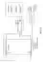
FIG. 3 shows a heat pump bypass refrigerant circuit 38 wherein the inlet of the 3 way valve 40 is connected to flow line 18 from the compressor 12. Outlet A of valve 40 is connected to flow line 18 and extends to the solar panel 14. Outlet B of valve 40 is connected to flow line 18 between the solar panel 14 and a reversing valve 46.
When powered by the reversing valve 46 heating signal from a thermostat and a signal from the solar panel 14, the computer 34 opens outlet A of the solenoid valve 40, which is normally closed, so that refrigerant flows through the solenoid valve 40 to the solar panel 14. While passing through the solar panel 14 the refrigerant absorbs additional BTUs from heat captured form the sun by the solar panel 14. The refrigerant then flows through the check valve 44, through the reversing valve 46, and on to continue through the system.
When not powered by the reversing valve 46 heating signal from the thermostat and the solar panel signal the computer 34 closes outlet A of the solenoid/ball valve 42 and opens outlet B so that refrigerant flows from the compressor 12 to the reversing valve and on through the system 10 while the check valve blocks the flow of refrigerant back in to the solar panel 14. FIG. 4 shows an electrical schematic of the heat pump bypass.
The computer 34, as shown in FIG. 5 has a communication link 48 and a 12/24 v AC or DC power link 50 to the solar panel 14. The computer 34 also has a signal conditioner and A/D converter 52, a monitor 54, an input device 56 such as a mouse and/or keyboard, and both electrical and wireless connections 58 to a building computer 59. A plurality of signals from the sensors 32 are received at an input terminal stop 60 and output signals are sent to the system from an output terminal stop 62.
The system provides the following tracker and base system features.
Tracker Features:
- 1. Be able to program variables over communications link, i.e. over-temp to turn east based on expected process operating temperature, maximum panel temperature differential (T discharge−T inlet), protect itself if panel is air bound or in no flow condition.
- 2. Self-configure on installation as to individual address in communication with base station.
- 3. Self-diagnostics: trouble shoot operational status and report if problem
Reset/reboot/restart panel software if problem and report status
If motor is trying to run too long (>1.5 minutes) report error and shut off motor
- 4. Automatically go to East limit if sensed temperatures go over programmed upper limit and report
- 5. Lightning protection, static protection and power supply fluctuation/noise protection on each computer board:
Zener/transzorb on 12/24 vdc, increase cap size
Zener/transzorb on 5 vdc, increase cap size
Noise Filters on all inputs/outputs of processor
- 6. Base station software to diagnose unbalanced fluid or gas flow and air bound panels through reported temperatures from panels
- 7. Use insolation value averaging program to determine if a panel needs to be cleaned and report to maintenance—use the system insolation meter to monitor the panel glass cleanliness by comparing the change in the tracker photo sensors. When the difference equals a settable percentage or settable level shift differential, then report the glass needs to be cleaned on identified panels.
- 8. Supports proprietary serial protocol and driver circuitry for interface to host controller.
- 9. Serial protocol to be based on bus architecture, allowing extensibility to support a large number of daisy-chain connected panels.
- 10. Each panel controller is assigned a unique address by the host controller for purposes of identification. Addresses may be assigned automatically or manually.
- 11. Assignment of addresses may be initiated by the user by initiating a “broadcast mode” on the host controller. While in broadcast mode, a new panel may be detected on the network, either by powering up the panel for the first time, or pressing a button on the remote panel's controller PCB.
- 12. Utilizes analog sampling of dual photovoltaic sensors to determine alignment to sun.
- 13. May deliberately misalign photo sensor assembly temporarily, in order to bring one sensor into full sunlight for the purposes of determining the solar insolation magnitude.
- 14. Incorporates analog circuitry for interfacing to thermistor, for the purpose of sampling inlet temperature, outlet temperature, ambient (outside) temperature, panel interior temperature, and motor enclosure temperature.
- 15. Additional analog inputs and buffer circuitry to be provided for future expandability. Such inputs are to be compatible with analog signals in the range 0-5 volts or 4-20 mA.
- 16. Digital inputs are to be provided for possible interface to a pulse-output flow meter or anemometer.
- 17. All digital and analog inputs are to be protected against voltage surges using TVS surge-suppression devices.
- 18. Monitors the output of two hall-effect sensors to determine east or west travel limit.
- 19. When queried by the host controller, all monitored parameters may be communicated to the host controller via the serial link.
- 20. Includes ability to report time interval since last move, so that the host controller may determine if the panel movement frequency is within expected limits.
- 21. Tracking function may be enabled or disabled on command from the host controller. The host controller may instruct the remote controller to return to the east limit.
- 22. Supports an automatic east-return function in the event than an over-temperature condition is sensed. This function is to operate independently of the host controller, in the event of a failure of the host controller.
- 23. Integrates a watchdog timer to determine proper code execution. When code is executing properly, a pulse is expected from the watchdog module at least once per defined time interval. The controller is to reset itself automatically if ever a watchdog pulse is not received within the last determined number of seconds.
- 24. Controller keeps a reset-count in nonvolatile memory. The host controller may read the reset-count to determine if the remote controller is experiencing frequent problems.
- 25. Program capability to monitor the discharge temperature of a working fluid or gas from the panel. Deliberately offset the parabolas from the sun position by turning on the tracking motor for enough seconds in the East direction degrees to allow panel temperature to return to below critical temperature. Then the computer can allow the tracker to follow the sun. This allows the panel to maintain the desired upper temperature of the working fluid or gas.
- 26. Computer/panel powered by PV panel with a battery storage system option.
- 27. Can add a light controlled by the computer to indicate that the tracker is functioning correctly.
- 28. Fuse on computer circuit board to protect against over current29 Power regulator circuitry on the circuit board for 24 volt or 12 volt AC or DC input for motor and computer control board.
- 29. Interface with heat pump controller for operating mode program.
Host Base Station Features:
- 1. Communicate over power wiring or separate twisted pair wire to each SunTrac Solar panel in series (one set of twisted pair wires for entire solar panel array)
- 2. Be able to convert signals into USB, Ethernet, RS485, Modbus, M bus, etc., for output into computer
- 3. Accept signals, as above, from the computer and convert into communication signals for each tracker
- 4. Accept additional inputs, e.g. pulse, 4-20 ma or 0-5V, from additional sensors such as: temperature sensors, flow meters, tank temperature, outside air temperature, solar insolation monitor, wind direction and velocity sensors
- 5. Communicate individual panel and system BTU levels to computer
- 6. Integrate software to Optimize heat collection efficiency
- 7. Turn the panel tracking on/off to be able to maintain a set temperature in storage tank , process water, working fluid or gas and eliminate over temperature/stagnation conditions
- 8. Ability to monitor and control energy output of solar thermal system by controlling panel tracking.
- 9. Have outputs to control pump functions—on/off, pump variable speed control to optimize energy capture
- 10. Eliminates need for separate pump controller
- 11. Eliminates additional panel output sensor and wiring back to pump controller
- 12. The temperature reporting from each panel allows perfect balancing of panel arrays using ball valves in each parallel/serial branch
- 13. Provides operations and maintenance complete detailed info on system status/performance
- 14. Can perform self-diagnostics and indicate predictive maintenance operations
- 15. Can provide information to internet based system to monitor performance
- 16. Can commission/decommission system remotely through internet access
- 17. Throttle thermal output of system back to match what was paid for by customer in contract
- 18. Turn panels and solar generation off if invoice is not paid for the energy provided to end user customer
- 19. SunTrac to sell hardware based on minimal performance guarantees—due additional money for increased performance
- 20. Installation contractor performance monitoring—actual panel output compared to the heat delivered into the process after heat losses in system installation and insulation on piping
- 21. Base station to report all parameters and all settable parameters input via internet or wired connection
Weather data—solar insolation values, ambient air temp, wind direction and velocity, etc.
Environmental CO2 equivalent reduction
BTU's generated from panels and BTU's delivered to process
PV energy generated from panels
Invoice generation and billing information for each base station system for thermal and electrical energy
Maintenance:
-
- Hardware: fix it now/preventive/predictive maintenance requirements Site information setup
- Data download on request or scheduled
- Dashboard editing
- Alerts
- 22. Options to set parameters in base station controller by: plugging in keyboard and monitor, laptop computer, through interne remotely, or through onsite desktop computer
- 23. Supports proprietary serial protocol and driver circuitry for interface to remote controllers.
- 24. Serial protocol to be based on bus architecture, allowing extensibility to support a large number of daisy-chain connected panels.
- 25. May initiate “Broadcast Mode”, whereby the system enters a continuous polling state in order to identify newly-installed remote panel controllers on the network. Once a new panel is detected, it may be assigned an identification number automatically, or the user may manually assign a unique identification number.
- 26. Incorporates analog circuitry for interfacing to multiple thermistors, for the purpose of sampling inlet and outlet temperatures of one to four storage tanks. Also includes thermistor inputs for sampling panel inlet- and outlet-manifold temperatures, and up to ten additional thermistor inputs for general use.
- 27. Buffered analog inputs support signals in the range 0-5 volts or 4-20 mA, for measuring the output of a flow meter, BTU meter, and the system power-supply voltage. Up to twelve additional general analog inputs are included, reserved for future expansion. These inputs may be used to monitor environmental conditions (Wind direction, baseline solar insolation, etc.). More analog inputs may be added at very low cost via serial multiplexing, if required.
- 28. Digital inputs to be provided for possible interface to a pulse-output flow meter or anemometer. Additional digital inputs to be included reserved for future expansion.
- 29. Digital or analog output included (as required) to control the flow rate of a variable-speed pump.
- 30. All digital and analog inputs are to be protected against voltage surges using TVS surge-suppression devices.
- 31. Host incorporates all logic function required for querying all remote panels in turn, recording the received values to memory, determining the existence of problem conditions, and taking appropriate action when problem conditions are determined.
- 32. Host may operate in Stand-Alone mode, or in conjunction with an external computer.
- 33. In Stand-Alone mode, the host controller may display values to an in-built backlit LCD display (optional), and the host controller may accept user input via an in-built tactile keypad (optional)
- 34. While connected to an external computer, all functions of the host controller are made accessible through the computer interface.
- 35. Computer link is via USB, RS232 serial, Ethernet (10-base-T), or wireless modem (GPRS functionality may be integrated in a possible second revision in order to speed development of the initial product).
- 36. As new firmware functionality is developed, units may be field-upgraded. New firmware is uploaded to the host controller via the computer interface.
- 37. Computer interface software is initially PC-only (proprietary exe), but in later revisions may be expanded to other platforms via a web-browser interface.
- 38. For the initial product, PC software may serve as a host gateway to allow other web-based platforms to access the host controller via a traditional client/server TCP-IP interface.
- 39. Host controller integrates a watchdog timer to determine proper code execution. When code is executing properly, a pulse is expected from the watchdog module at least once per second. The controller is to reset itself automatically if ever a watchdog pulse is not received within the defined time interval.
- 40. Perform Data logging function showing past performance
- 41. Tracking motor on/off indicator light—light controlled by the computer to indicate that the tracker is functioning correctly.
Claims
What is claimed is:1. A solar hybrid system, comprising:
a compressor, a solar panel, a condenser, and an evaporator in fluid connection to form a closed circuit;
the solar panel having a plurality of parabolic reflectors mounted within a glassed-topped enclosure that is capable of pivotal movement throughout the course of the day based upon movement of the sun.
2. The system of claim 1 further comprising an expansion valve connected between the condenser and the evaporator.
3. The system of claim 2 further comprising a second expansion valve connected between the first expansive valve and the condenser.
4. The system of claim 2 having a three-way bypass valve connected between the evaporator and the condenser.
5. The system of claim 1 having a heat pump bypass circuit connected between the condenser, the solar panel, and a reversing valve.
6. A solar hybrid system, comprising:
a compressor, a solar panel, a condenser, and an evaporator in fluid connection to form a closed circuit;
a heat pump bypass circuit connected between the condenser, the solar panel, and a reversing valve;
a computer connected to the reversing valve, the heat pump bypass circuit, and the solar panel;
wherein the computer is capable of activating and deactivating the heat pump bypass circuit based upon a heat signal from the reversing valve and the solar panel.
Images & Drawings included:


Sources:
- United States Patent and Trademark Office - verify current appl. status at the USPTO↗
Recent applications in this class:
- » 20230258374 2023-08-17
THERMAL PRESSURIZATION CHAMBERS WITH SEQUENTIALLY CONTROLLED OPERATION FOR USE IN AN AIR CONDITIONING UNIT - » 20220282893 2022-09-08
Air conditioning system with solar-powered subcooling system - » 20220026120 2022-01-27
Thermal cell panel system for heating and cooling and associated methods - » 20220026119 2022-01-27
Electromagnetic cooling and heating - » 20200340716 2020-10-29
DC system controls - » 20200309422 2020-10-01
METHOD FOR OPERATING A HEAT PUMP SYSTEM, HEAT PUMP SYSTEM AND HVAC SYSTEM - » 20190195540 2019-06-27
SOLAR POWERED FREEZER TRUCK - » 20180135899 2018-05-17
AN IMPROVED TEMPERATURE CONTROL SYSTEM - » 20180128519 2018-05-10
Solar Turbo Pump - Hybrid Heating Air-Conditioning and Method of Operation - » 20180106510 2018-04-19
DC refrigeration system controls