Regenerative braking control system and method
US20150274018A1
2015-10-01
14/225,029
2014-03-25
✅ Patent granted
US 9,493,075 B2
2016-11-15
-
-
Thomas G Black | Sze-Hon Kong
David Kelley, Esq. | Tung & Associates
2034-08-05
Abstract:
A system for controlling regenerative braking in an electrified vehicle to prevent or minimize reduction of overall braking torque during wheel slip events includes an antilock braking system adapted to transmit an antilock braking system active signal and a regeneration powertrain interfacing with the antilock braking system. The regeneration powertrain is adapted to inhibit regenerative braking torque reduction responsive to receiving the antilock braking system active signal during a high deceleration braking event. A method for controlling regenerative braking in an electrified vehicle to prevent or minimize reduction of overall braking torque during wheel slip events is also disclosed.
Inventors:
- Dale Scott Crombez 85 🇺🇸 Livonia, MI, United States
- Kerem Bayar 6 🇺🇸 Ann Arbor, MI, United States
Assignee:
- FORD GLOBAL TECHNOLOGIES, LLC 23,240 🇺🇸 Dearborn, MI, United States
Applicant:
Interested in similar patents?
Get notified when new applications in this technology area are published.
Classification:
Y10S903/947 » CPC further
Hybrid electric vehicles, HEVS; Prime movers comprising electrical and internal combustion motors having energy storing means, e.g. battery, capacitor Characterized by control of braking, e.g. blending of regeneration, friction braking
B60L7/18 » CPC main
Electrodynamic brake systems for vehicles in general; Dynamic electric regenerative braking Controlling the braking effect
B60W20/00 » CPC further
Control systems specially adapted for hybrid vehicles
B60L3/108 » CPC further
Electric devices on electrically-propelled vehicles for safety purposes; Monitoring operating variables, e.g. speed, deceleration or energy consumption; Indicating wheel slip ; Correction of wheel slip for maintaining or recovering the adhesion of the drive wheels whilst braking, i.e. ABS
B60L15/2009 » CPC further
Methods, circuits, or devices for controlling the traction-motor speed of electrically-propelled vehicles for control of the vehicle or its driving motor to achieve a desired performance, e.g. speed, torque, programmed variation of speed for braking
B60T13/586 » CPC further
Transmitting braking action from initiating means to ultimate brake actuator with power assistance or drive; Brake systems incorporating such transmitting means, e.g. air-pressure brake systems with fluid assistance, drive, or release; Combined or convertible systems comprising friction brakes and retarders the retarders being of the electric type
B60W20/14 » CPC further
Control systems specially adapted for hybrid vehicles; Controlling the power contribution of each of the prime movers to meet required power demand in order to stay within battery power input or output limits; in order to prevent overcharging or battery depletion in conjunction with braking regeneration
B60W30/18127 » CPC further
Purposes of road vehicle drive control systems not related to the control of a particular sub-unit, e.g. of systems using conjoint control of vehicle sub-units, or advanced driver assistance systems for ensuring comfort, stability and safety or drive control systems for propelling or retarding the vehicle; Propelling the vehicle related to particular drive situations; Braking Regenerative braking
B60W2510/182 » CPC further
Input parameters relating to a particular sub-units; Braking system Brake pressure, e.g. of fluid or between pad and disc
B60Y2300/89 » CPC further
Purposes or special features of road vehicle drive control systems Repartition of braking force, e.g. friction braking versus regenerative braking
B60L15/20 IPC
Methods, circuits, or devices for controlling the traction-motor speed of electrically-propelled vehicles for control of the vehicle or its driving motor to achieve a desired performance, e.g. speed, torque, programmed variation of speed
B60T8/52 » CPC further
Arrangements for adjusting wheel-braking force to meet varying vehicular or ground-surface conditions, e.g. limiting or varying distribution of braking force responsive to a speed condition, e.g. acceleration or deceleration Torque sensing, i.e. wherein the braking action is controlled by forces producing or tending to produce a twisting or rotating motion on a braked rotating member
B60L7/14 » CPC further
Electrodynamic brake systems for vehicles in general; Dynamic electric regenerative braking for vehicles propelled by ac motors
B60L7/26 » CPC further
Electrodynamic brake systems for vehicles in general with additional mechanical or electromagnetic braking Controlling the braking effect
B60T8/176 » CPC further
Arrangements for adjusting wheel-braking force to meet varying vehicular or ground-surface conditions, e.g. limiting or varying distribution of braking force; Using electrical or electronic regulation means to control braking Brake regulation specially adapted to prevent excessive wheel slip during vehicle deceleration, e.g. ABS
B60T8/17 » CPC further
Arrangements for adjusting wheel-braking force to meet varying vehicular or ground-surface conditions, e.g. limiting or varying distribution of braking force Using electrical or electronic regulation means to control braking
B60T1/10 » CPC further
Arrangements of braking elements, i.e. of those parts where braking effect occurs specially for vehicles acting by retarding wheels by utilising wheel movement for accumulating energy, e.g. driving air compressors
B60T13/58 IPC
Transmitting braking action from initiating means to ultimate brake actuator with power assistance or drive; Brake systems incorporating such transmitting means, e.g. air-pressure brake systems with fluid assistance, drive, or release Combined or convertible systems
B60W10/08 » CPC further
Conjoint control of vehicle sub-units of different type or different function including control of propulsion units including control of electric propulsion units, e.g. motors or generators
B60W10/184 » CPC further
Conjoint control of vehicle sub-units of different type or different function including control of braking systems with wheel brakes
B60W30/18 IPC
Purposes of road vehicle drive control systems not related to the control of a particular sub-unit, e.g. of systems using conjoint control of vehicle sub-units, or advanced driver assistance systems for ensuring comfort, stability and safety or drive control systems for propelling or retarding the vehicle Propelling the vehicle
F16D61/00 » CPC further
Brakes with means for making the energy absorbed available for use
B60L3/10 IPC
Electric devices on electrically-propelled vehicles for safety purposes; Monitoring operating variables, e.g. speed, deceleration or energy consumption Indicating wheel slip ; Correction of wheel slip
B60W30/09 » CPC further
Purposes of road vehicle drive control systems not related to the control of a particular sub-unit, e.g. of systems using conjoint control of vehicle sub-units, or advanced driver assistance systems for ensuring comfort, stability and safety or drive control systems for propelling or retarding the vehicle predicting or avoiding probable or impending collision Taking automatic action to avoid collision, e.g. braking and steering
Description
FIELD
Illustrative embodiments of the disclosure generally relate to regenerative braking. More particularly, illustrative embodiments of the disclosure relate to a system and method for controlling regenerative braking to prevent or minimize reduction of overall braking torque during wheel slip events.
BACKGROUND
To improve fuel economy, hybrid electric vehicles (HEVs) may utilize regenerative (regen) braking, in which kinetic energy is converted by an electric machine into storable energy during braking and then made available for vehicle propulsion. During a wheel slip event (e.g., an ABS event), regenerative braking may be removed. The transition from regenerative braking to friction braking may be abrupt and may result in a temporary reduction in overall braking torque as the regenerative braking is removed and the friction braking is applied. If the ABS event occurs on a surface with a low friction coefficient, a faster rate of regenerative braking reduction may be advantageous since it may minimize wheel lockup. However, if the slip event occurs on a surface with a high friction coefficient, fast regenerative braking reduction may not necessarily be advantageous. For example, if a wheel slip event occurs during a CMbB (Collision Mitigation by Brakes) event, especially at higher decelerations, it may not be necessary to reduce regenerative braking fast or even at all since such reduction may result in a 100-200 ms delay in overall braking torque generation.
Accordingly, a system and method for controlling regenerative braking to prevent or minimize reduction of overall braking torque during wheel slip events is needed.
SUMMARY
Illustrative embodiments of the disclosure are generally directed to a system for controlling regenerative braking in an electrified vehicle to prevent or minimize reduction of overall braking torque during wheel slip events. An illustrative embodiment of the system includes an antilock braking system adapted to transmit an antilock braking system active signal and a regeneration powertrain interfacing with the antilock braking system. The regeneration powertrain is adapted to inhibit regenerative braking torque reduction responsive to receiving the antilock braking system active signal during a high deceleration braking event.
Illustrative embodiments of the disclosure are further generally directed to a method for controlling regenerative braking in an electrified vehicle to prevent or minimize reduction of overall braking torque during wheel slip events. An illustrative embodiment of the method includes determining whether an antilock braking system is active, determining whether a high deceleration braking event is occurring and inhibiting reduction of regeneration braking torque if the high deceleration braking event is occurring.
BRIEF DESCRIPTION OF THE DRAWINGS
Illustrative embodiments of the disclosure will now be described, by way of example, with reference to the accompanying drawings, in which:
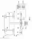
FIG. 1 is a schematic block diagram of an illustrative embodiment of the system for controlling regenerative braking to prevent or minimize reduction of overall braking torque during wheel slip events;
FIG. 2 is a block diagram of an illustrative embodiment of the method for controlling regenerative braking to prevent or minimize reduction of overall braking torque during wheel slip events; and
FIG. 3 is a block diagram of an alternative illustrative embodiment of the method for controlling regenerative braking to prevent or minimize reduction of overall braking torque during wheel slip events.
DETAILED DESCRIPTION
The following detailed description is merely exemplary in nature and is not intended to limit the described embodiments or the application and uses of the described embodiments. As used herein, the word “exemplary” or “illustrative” means “serving as an example, instance, or illustration.” Any implementation described herein as “exemplary” or “illustrative” is not necessarily to be construed as preferred or advantageous over other implementations. All of the implementations described below are exemplary implementations provided to enable persons skilled in the art to practice the disclosure and are not intended to limit the scope of the claims. Moreover, the illustrative embodiments described herein are not exhaustive and embodiments or implementations other than those which are described herein and which fall within the scope of the appended claims are possible. Furthermore, there is no intention to be bound by any expressed or implied theory presented in the preceding technical field, background, brief summary or the following detailed description.
Referring initially to FIG. 1, an illustrative embodiment of the system for controlling regenerative braking to prevent or minimize reduction of overall braking torque during wheel slip events, hereinafter system, in implementation of an electrified vehicle 100, is generally indicated by reference numeral 110. The vehicle 100 may be a hybrid electric vehicle (HEV) or a plug-in hybrid electric vehicle (PHEV), for example and without limitation. The vehicle 100 may have a front axle 101 with a pair of front wheels 102 and a rear axle 104 with a pair of rear wheels 105.
The system 110 may include a regenerative powertrain 112 which interfaces with at least one of the front axle 101 and the rear axle 104 of the vehicle 100. In some embodiments, the regenerative powertrain 112 may interface with one or more front wheels 102 and/or one or more rear wheels 105 of the vehicle 100. The regenerative powertrain 112 may be adapted to apply regenerative torque to the front axle 101 and/or the rear axle 104 during braking of the vehicle 100, typically in the conventional manner. The regenerative powertrain 112 may be adapted to convert mechanical power from the rotating front axle 101 and/or rear axle 104 into electrical power. The electrical power may be stored in a battery or other suitable electrical storage facility 113 which electrically interfaces with the regenerative powertrain 112. The electrical power which is stored in the electrical storage facility 113 may be used in propulsion of the vehicle 100 such as in the conventional manner.
At least one sensor 116 may interface with the regenerative powertrain 108. The sensor 116 may include a drive shaft position sensor 118, for example and without limitation, which is provided on a draft shaft (not illustrated) of the vehicle 100. During operation of the vehicle 100, the drive shaft position sensor 118 may be adapted to detect wheel slip events at the front wheels 102 and/or the rear wheels 105 of the vehicle 100 using a limited slip control detection algorithm such as in the conventional manner. The drive shaft position sensor 118 may be further adapted to transmit a drive shaft position sensor signal 119 which indicates the wheel slip events to the regenerative powertrain 112.
In some embodiments, the sensors 116 may include at least one vehicle motion sensor 120 which interfaces with the regenerative powertrain 112. The vehicle motion sensor 120 may include at least one wheel speed sensor and/or at least one acceleration sensor (such as a longitudinal acceleration sensor, a lateral acceleration sensor, etc.), for example and without limitation. The vehicle motion sensor 120 may be adapted to transmit a motion sensor signal 121 which indicates wheel slip events to the regenerative powertrain 112.
An ABS (Antilock Brake) system 114 of the vehicle 100 may interface with the regenerative powertrain 112. The ABS system 114 may be adapted to transmit an ABS active signal 115 to the regenerative powertrain 112 during braking of the vehicle 100. The ABS active signal 115 may be transmitted from the ABS system 114 to the regen powertrain 112 via a CAN (controller area network, not shown).
In exemplary application of the system 110, at the onset of braking, the regenerative powertrain 112 applies torque to the front axle 101 and/or the rear axle 104 during braking of the vehicle 100. The regenerative powertrain 112 generates electrical power which may be stored in the electrical storage facility 113 and may be used in propulsion of the vehicle 100. Depending on the type of surface (e.g., friction coefficient) on which the vehicle 100 is traveling, the ABS system 114 may be engaged during braking of the vehicle 100 to ensure optimal braking of the vehicle 102 on the surface and prevent or eliminate wheel slip. Upon engagement, the ABS system 114 transmits the ABS active signal 115 to the regenerative powertrain 112. Accordingly, responsive to the ABS active signal 115, the regenerative powertrain 112 may normally reduce regenerative braking torque which is applied to the front axle 101, the front wheels 102, the rear axle 104 and/or the rear wheels 105 to increase friction braking torque.
In the event that wheel slippage occurs during a high deceleration braking event such as a CMbB (Collision Mitigation by Brakes) event, the regenerative powertrain 112 may receive input from the ABS system 114 via the ABS active signal 115. The regenerative powertrain 112 may inhibit or prevent reduction in regenerative braking torque which is applied to the front axle 101, the front wheels 102, the rear axle 104 and/or the rear wheels 105. Friction braking torque may then be applied to the front axle 101, the front wheels 102, the rear axle 104 and/or the rear wheels 105. Therefore, the transition between application of regenerative braking torque and application of friction braking torque may be substantially continuous or seamless and may substantially reduce or eliminate reduction in overall braking torque which is applied to the vehicle 100 during the CMbB event.
In some embodiments, the regenerative powertrain 112 may inhibit or prevent reduction in regenerative braking torque which is applied to the front axle 101, the front wheels 102, the rear axle 104 and/or the rear wheels 105 if the friction braking torque pressure is sufficient to modulate the ABS system 114 without having to reduce regenerative braking torque during the high deceleration braking event. This may be carried out alone or in combination with inhibiting or preventing reduction in regenerative braking torque during a CMbB event.
Referring next to FIG. 2, a block diagram 200 of an illustrative embodiment of a method for controlling regenerative braking to prevent or minimize reduction of overall braking torque during wheel slip events during a high deceleration braking event is shown. The method 200 may begin at block 202 at the onset of braking. In some embodiments, a determination may be made as to whether the ABS system is active at block 204. If not, then regenerative braking may be applied at block 206 and friction braking may be applied at block 208. The method may end at block 210.
If the ABS system is active at block 204, a determination may be made as to whether a CMbB (Collision Mitigation by Brakes) event is occurring at block 212. If a CMbB event is occurring, then at block 214, ABS regenerative torque reduction may be inhibited or prevented and at block 208, friction braking may be applied. The method may end at block 212.
If a CMbB event is not occurring at block 212, then ABS regenerative braking torque reduction may not be inhibited at block 216. Friction braking may be applied at block 208 and the method may end at block 210.
Referring next to FIG. 3, an alternative illustrative embodiment of the method for controlling regenerative braking to prevent or minimize reduction of braking torque during wheel slip events during a high deceleration braking event is shown. The method 300 may begin at block 302 at the onset of braking. In some embodiments, a determination may be made as to whether the ABS system is active at block 304. If not, then regenerative braking may be applied at block 306 and friction braking may be applied at block 308. The method may end at block 310.
If the ABS system is active at block 304, a determination may be made as to whether friction brake torque (pressure) which is being applied to the vehicle is of sufficiently large magnitude to modulate ABS controls without reducing application of regenerative braking torque. If yes, then at block 314 ABS regenerative torque reduction may be inhibited or prevented and at block 308, friction braking may be applied. The method may end at block 310.
If friction brake torque (pressure) which is being applied to the vehicle is not of sufficiently large magnitude to modulate ABS controls without reducing application of regenerative braking torque at block 312, then ABS regenerative braking torque reduction may not be inhibited at block 316. Friction braking may be applied at block 308 and the method may end at block 310.
Although the embodiments of this disclosure have been described with respect to certain exemplary embodiments, it is to be understood that the specific embodiments are for purposes of illustration and not limitation, as other variations will occur to those of skill in the art.
Claims
What is claimed is:1. A system for controlling regenerative braking in an electrified vehicle to prevent or minimize reduction of overall braking torque during wheel slip events, comprising:
an antilock braking system adapted to transmit an antilock braking system active signal; and
a regeneration powertrain interfacing with the antilock braking system, the regeneration powertrain adapted to inhibit regenerative braking torque reduction responsive to receiving the antilock braking system active signal during a high deceleration braking event.
2. The system of claim 1 wherein the vehicle comprises a hybrid electric vehicle.
3. The system of claim 1 wherein the vehicle comprises a plug-in hybrid electric vehicle.
4. The system of claim 1 further comprising an electrical storage facility adapted to store electrical power from the regenerative braking system.
5. The system of claim 1 wherein the regeneration powertrain is adapted to apply regenerative torque to at least one of a front axle and a rear axle of the vehicle.
6. The system of claim 1 wherein the regeneration powertrain is adapted to apply regenerative torque to a selected one of front wheels and rear wheels of the vehicle.
7. The system of claim 1 wherein the regeneration powertrain is adapted to inhibit regenerative braking torque reduction responsive to receiving the antilock braking system active signal during a collision mitigation by brakes event.
8. The system of claim 1 wherein the regeneration powertrain is adapted to inhibit regenerative braking torque reduction responsive to receiving the antilock braking system active signal if friction braking torque pressure is sufficiently large to modulate the antilock braking system without reducing the regenerative braking.
9. The system of claim 1 wherein the regeneration powertrain is adapted to apply regeneration braking torque if the regeneration powertrain does not receive the antilock braking system active signal from the antilock braking system.
10. The system of claim 1 wherein the regeneration powertrain is adapted to not inhibit regenerative braking torque reduction if the high deceleration braking event is not occurring.
11. A method for controlling regenerative braking in an electrified vehicle to prevent or minimize reduction of overall braking torque during wheel slip events, comprising:
inhibiting reduction of regeneration braking torque if a high deceleration braking event is occurring when an antilock braking system is active.
12. The method of claim 11 further comprising applying regeneration braking torque if the antilock braking system is not active.
13. The method of claim 12 further comprising applying friction braking if the antilock braking system is not active.
14. The method of claim 11 further comprising not inhibiting reduction of regeneration braking torque if the high deceleration event is not occurring.
15. The method of claim 11 further comprising determining whether a high deceleration braking event is occurring by determining whether a collision mitigation by brakes event is occurring.
16. A method for controlling regenerative braking in an electrified vehicle to prevent or minimize reduction of overall braking torque during wheel slip events, comprising:
inhibiting reduction of regeneration braking torque if the friction braking torque pressure is sufficiently large to modulate an antilock braking system without reducing the regenerative braking.
17. The method of claim 16 further comprising applying regeneration braking torque if the antilock braking system is not active.
18. The method of claim 17 further comprising applying friction braking if the antilock braking system is not active.
19. The method of claim 16 further comprising not inhibiting reduction of regeneration braking torque if the friction braking torque pressure is not sufficiently large to modulate the antilock braking system without reducing the regenerative braking.
20. The method of claim 16 further comprising determining whether a collision mitigation by brakes event is occurring and inhibiting reduction of regeneration braking torque if the collision mitigation by brakes event is occurring.
Images & Drawings included:


Sources:
- United States Patent and Trademark Office - verify current appl. status at the USPTO↗
Similar patent applications:
- » 20120078481
Regenerative braking system and method for controlling a regenerative braking system - » 20250162587
APPARATUS AND METHOD FOR CONTROLLING REGENERATIVE BRAKING OF VEHICLE, AND SYSTEM AND METHOD FOR CONTROLLING REGENERATIVE BRAKING BETWEEN VEHICLES - » 20180093572
Regenerative braking control method and system - » 20160121729
Method for controlling regenerative brake system for vehicle - » 20110049969
Hydraulic control method of regenerative braking system for vehicle - » 20070108838
REGENERATIVE BRAKING CONTROL SYSTEM AND METHOD - » 20150197227
Regenerative braking control system and method - » 20150217643
Regenerative braking control system and method - » 20100312447
Regenerative brake control system and method - » 20160190959
Regenerative braking controlling system and method
Recent applications in this class:
- » 20250222778 2025-07-10
Using ‘Dynamic Regenerative Braking’ to Enhance Crash Avoidance - » 20250206144 2025-06-26
COMPUTER SYSTEM AND METHOD FOR ELECTRICALLY PROPELLED VEHCILE - » 20250206143 2025-06-26
ENABLING PROLONGED ENDURANCE BRAKING - » 20250178447 2025-06-05
CONTROLLER FOR ELECTRIC VEHICLE - » 20250178446 2025-06-05
DYNAMIC REGENERATIVE BRAKING SYSTEM - » 20250162426 2025-05-22
DRIVE AXLE SYSTEM AND METHOD OF CONTROL - » 20250135898 2025-05-01
ELECTRIFIED VEHICLE AND METHOD OF CONTROLLING REGENERATIVE BRAKING THEREOF - » 20250121696 2025-04-17
COLD START INDUCTION HEATING AND BRAKING ARRANGEMENT - » 20250108696 2025-04-03
SYSTEMS AND METHODS FOR TOWING ELECTRIC VEHICLES - » 20250091445 2025-03-20
ELECTRIC VEHICLE WITH REGENERATIVE BRAKING
Recent applications for this Assignee:
- » 20250293257 2025-09-18
LITHIUM-ION BATTERY COMPONENT WITH POLAR BINDER - » 20250289391 2025-09-18
MANIFOLD TO SELECTIVELY INFLATE SEAT AIRBAGS - » 20250289296 2025-09-18
SUN VISOR FOR A MOTOR VEHICLE - » 20250285043 2025-09-11
REFACTORING INPUT STRINGS - » 20250282426 2025-09-11
VEHICLE STRUCTURAL ASSEMBLY HAVING STRUT CAPS - » 20250282423 2025-09-11
STRUCTURAL ASSEMBLY HAVING POCKETS - » 20250282315 2025-09-11
RETRACTABLE BUMPER ASSEMBLY WITH LOCK - » 20250282220 2025-09-11
VEHICLE DISPLAY CONTROL - » 20250278084 2025-09-04
SYSTEMS AND METHODS FOR ENABLING VEHICLE MOVEMENT VIA FORCE APPLIED TO AN EXTERNAL INTERFACE - » 20250277401 2025-09-04
SYSTEMS AND METHODS FOR CONTROLLING VEHICLE COMPONENT OPERATION BASED ON USER DEVICE MOVEMENT PATTERN