Rotary table device having multi-worm shaft
US20150276019A1
2015-10-01
14/647,096
2013-12-02
✅ Patent granted
US 9,874,265 B2
2018-01-23
WO; PCT/KR2013/011066; 20131202
WO; WO2014/098388; 20140626
Ha D Ho
2034-09-11
Abstract:
A rotary table device is provided, which includes a housing having a space portion formed therein, a main shaft installed in the space portion and provided with a worm wheel coupled along an outer circumference thereof, a pair of worm shafts provided to be engaged with the worm wheel at both sides of the worm wheel in a predetermined position of the space portion, a driving motor installed on one side of the housing, a power transmission member installed on an upper surface of the housing to transmit a driving force of the driving motor to the pair of worm shafts, and a clearance adjustment member installed in a predetermined position of each lower end of both sides of the housing.
Applicant:
Interested in similar patents?
Get notified when new applications in this technology area are published.
Classification:
B23Q16/02 IPC
Equipment for precise positioning of tool or work into particular locations not otherwise provided for Indexing equipment
B23Q16/025 » CPC further
Equipment for precise positioning of tool or work into particular locations not otherwise provided for; Indexing equipment in which only the indexing movement is of importance by converting a continuous movement into a rotary indexing movement
F16H1/22 » CPC main
Toothed gearings for conveying rotary motion without gears having orbital motion involving more than two intermeshing members with a plurality of driving or driven shafts; with arrangements for dividing torque between two or more intermediate shafts
F16H57/12 » CPC further
General details of gearing Arrangements for adjusting or for taking-up backlash not provided for elsewhere
F16H37/041 » CPC further
Combinations of mechanical gearings, not provided for in groups - comprising essentially only toothed or friction gearings; Combinations of toothed gearings only for conveying rotary motion with constant gear ratio
F16H37/06 IPC
Combinations of mechanical gearings, not provided for in groups - comprising essentially only toothed or friction gearings with a plurality of driving or driven shafts; with arrangements for dividing torque between two or more intermediate shafts
F16H37/04 IPC
Combinations of mechanical gearings, not provided for in groups - comprising essentially only toothed or friction gearings Combinations of toothed gearings only
F16H1/225 » CPC further
Toothed gearings for conveying rotary motion without gears having orbital motion involving more than two intermeshing members with a plurality of driving or driven shafts; with arrangements for dividing torque between two or more intermediate shafts with non-parallel axes with two or more worm and worm-wheel gearings
F16H7/023 » CPC further
Gearings for conveying rotary motion by endless flexible members with belts; with V-belts with belts having a toothed contact surface or regularly spaced bosses or hollows for slipless or nearly slipless meshing with complementary profiled contact surface of a pulley
H02K7/116 IPC
Arrangements for handling mechanical energy structurally associated with dynamo-electric machines, e.g. structural association with mechanical driving motors or auxiliary dynamo-electric machines; Structural association with clutches, brakes, gears, pulleys or mechanical starters with gears
F16H1/16 IPC
Toothed gearings for conveying rotary motion without gears having orbital motion involving only two intermeshing members with non-parallel axes comprising worm and worm-wheel
B23Q5/56 » CPC further
Driving or feeding mechanisms; Control arrangements therefor; Arrangements or details not restricted to group or group respectively, e.g. control handles Preventing backlash
F16H7/02 IPC
Gearings for conveying rotary motion by endless flexible members with belts; with V-belts
F16H7/18 » CPC further
Gearings for conveying rotary motion by endless flexible members Means for guiding or supporting belts, ropes, or chains
Y10T74/19019 » CPC further
Machine element or mechanism; Gearing Plural power paths from prime mover
Description
TECHNICAL FIELD
The present disclosure relates to a rotary table device having a multi-worm shaft, and more particularly, to a rotary table device having a multi-worm shaft, which can minimize backlash that occurs due to wear between a worm wheel and a worm shaft.
BACKGROUND ART
In general, a rotary table device is installed in various kinds of machine tools and processes a workpiece through rotational division of the workpiece at a predetermined angle.
The rotary table device includes a housing to which a driving motor is coupled, and a main shaft and a worm shaft coupled to an outer circumference of a worm wheel provided in a space portion formed in the housing.
In the rotary table device, the worm shaft and the worm wheel are tooth-engaged with each other, and the worm wheel divides a rotating angle finely and precisely through rotation of the worm shaft.
However, the worm shaft and the worm wheel of the rotary table device in the related art have the problems that uneven wear occurs when in use, and an error occurs in a gap between the worm shaft and the worm wheel to greatly deteriorate the efficiency of the rotary table device.
Further, the worm shaft and the worm wheel of the rotary table device also have the problems that it is difficult to easily grasp the engagement state between the worm shaft and the worm wheel due to a long-term use and to finely adjust the gap in accordance with the engagement state.
DISCLOSURE
Technical Problem
Accordingly, the present disclosure has been made to solve the aforementioned problems occurring in the prior art, and it is an object of the present disclosure to provide a rotary table device having a multi-worm shaft, which can adjust a gap between a worm wheel and a worm shaft so as to prevent uneven wear which occurs due to backlash that occurs between the worm wheel and the worm shaft.
Technical Solution
To achieve the above objects, according to one aspect of the present disclosure, there is provided a rotary table device, which includes a housing having a space portion formed therein; a main shaft installed in the space portion and provided with a worm wheel coupled along an outer circumference thereof; a pair of worm shafts provided to be engaged with the worm wheel at both sides of the worm wheel in a predetermined position of the space portion; a driving motor installed on one side of the housing; a power transmission member installed on an upper surface of the housing to transmit a driving force of the driving motor to the pair of worm shafts; and a clearance adjustment member installed in a predetermined position of each lower end of both sides of the housing.
The power transmission member may include a pair of belt pulleys provided on the upper surface of the housing and coupled to each end portion of the pair of worm shafts; a pair of idle gears provided in a predetermined position of the upper surface of the housing so as to be positioned between the pair of belt pulleys; and a belt connecting the pair of belt pulleys and the pair of idle gears to a driving shaft of the driving motor.
The pair of belt pulleys and the pair of idle gears are connected to each other through the driving shaft of the driving motor and a chain.
At least one of the pair of idle gears may be provided on the upper surface of the housing so as to adjust a tension of the belt that connects the driving shaft of the driving motor and the pair of belt pulleys to each other, and be slidably coupled to a plate having a slot formed in a center portion thereof.
The clearance adjustment member may include a pair of coupling portions symmetrically coupled to predetermined positions of the both sides of the housing; and adjustment portions screw-engaged to penetrate centers of the coupling portions, wherein the adjustment portions adjust a gap between the worm wheel and the worm shaft through pressing of outer sides of the pair of worm shafts.
Advantageous Effect
According to the rotary table device having the multi-worm shaft according to an embodiment of the present disclosure, the gap between the worm wheel and the worm shaft can be adjusted so as to prevent the uneven wear which occurs due to the backlash that occurs between the worm wheel and the worm shaft.
BRIEF DESCRIPTION OF THE DRAWINGS
FIG. 1 is a perspective view of a rotary table device having a multi-worm shaft according to an embodiment of the present disclosure;
FIG. 2 is an exploded perspective view of a rotary table device having a multi-worm shaft according to an embodiment of the present disclosure;
FIG. 3 is a front view of a rotary table device having a multi-worm shaft according to an embodiment of the present disclosure;
FIG. 4 is a rear view of a rotary table device having a multi-worm shaft according to an embodiment of the present disclosure;
FIG. 5 is a perspective view of a rotary table device having a slide portion according to an embodiment of the present disclosure; and
FIG. 6 is a perspective view of a rotary table device having a multi-worm shaft according to a modified embodiment of the present disclosure.
EXPLANATION OF REFERENCE NUMERALS FOR MAIN PARTS IN THE DRAWING
- 10: rotary table device
- 100: housing
- 110: space portion
- 200: main shaft
- 210: worm wheel
- 220: cover
- 300: a pair of worm shafts
- 310: worm shaft holder
- 311: first horizontal portion
- 312: second horizontal portion
- 313: cut portion
- 400: driving motor
- 410: fixing bracket
- 420: driving shaft
- 500: power transmission member
- 510: a pair of belt pulleys
- 520: a pair of idle gears
- 521: slot hole
- 522: plate
- 530: belt
- 531: chain
- 532: sprocket
- 600: clearance adjustment member
- 610: coupling portion
- 612: adjustment portion
PREFERRED EMBODIMENTS OF THE INVENTION
Hereinafter, preferred embodiments of the present disclosure will be described in detail with reference to the accompanying drawings. In describing the present disclosure, the thickness of lines or the size of constituent elements illustrated in the drawings may be exaggerated for clarity and convenience in explanation.
Further, all terms used in the description are terms that are defined in consideration of their functions in the present disclosure, and may differ depending on intentions of a user or an operator or customs. Accordingly, they should be defined on the basis of the contents of the whole description of the present disclosure.
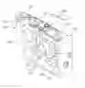
FIG. 1 is a perspective view of a rotary table device having a multi-worm shaft according to an embodiment of the present disclosure, and FIG. 2 is an exploded perspective view of a rotary table device having a multi-worm shaft according to an embodiment of the present disclosure. FIG. 3 is a front view of a rotary table device having a multi-worm shaft according to an embodiment of the present disclosure, and FIG. 4 is a rear view of a rotary table device having a multi-worm shaft according to an embodiment of the present disclosure. FIG. 5 is a perspective view of a rotary table device having a slide portion according to an embodiment of the present disclosure, and FIG. 6 is a perspective view of a rotary table device having a multi-worm shaft according to a modified embodiment of the present disclosure.
Referring to FIGS. 1 to 4, a rotary table device 10 having a multi-worm shaft according to an embodiment of the present disclosure is configured to include a housing 100, a main shaft 200, a pair of worm shafts 300, a driving motor 400, a power transmission member 500, and a clearance adjustment member 600.
The housing 100 is in a rectangular shape, and has a space portion 110 formed therein.
The main shaft 200 is provided in the space portion 110 that is formed inside the housing 100, and a worm wheel 210 having a gear portion formed thereon is coupled along an outer circumference thereof.
On the other hand, on the side of the main shaft 200 to which the worm wheel 210 is coupled, a cover 220 for protecting the main shaft 200 is provided to be coupled to the housing 100.
The pair of worm shafts 300 are provided to be tooth-engaged with the worm wheel 210 at both sides of the worm wheel 210 in the space portion 110 formed inside the housing 100.
One end portion of the pair of worm shafts 300 is coupled to a pair of belt pulleys 510 that are coupled to the upper surface of the housing 100, and the other end portion thereof is coupled to a worm shaft holder 310 that is provided in a predetermined position of a bottom surface of the space portion 110.
Here, the worm shaft holder 310 includes a first horizontal portion 311 that is coupled to the bottom surface of the space portion 110 provided in the housing 100, a second horizontal portion 312 that is formed to extend from one side of an upper portion of the first horizontal portion 311 to an outside, and a cut portion 313 which is formed on the second horizontal portion 312 and to which the other end portion of the worm shaft 300 is inserted and coupled.
The driving motor 400 is provided on one side of the housing 100 and drives the pair of worm shafts 300 through the power transmission member 500 to be described later.
The driving motor 400 is coupled to one side of the housing 100 by a “”-shaped fixing bracket 410.
The power transmission member 500 includes a pair of belt pulleys 510 provided on the upper surface of the housing 100, a pair of idle gears 520, and a belt 530, and transmits a driving force of the driving motor 400 to the pair of worm shaft 300.
The power transmission member 500 is configured to include the pair of belt pulleys 510 provided on the upper surface of the housing 100 and coupled to one end portion of the pair of worm shafts 300, the pair of idle gears 520 provided in a predetermined position of the upper surface of the housing so as to be positioned between the pair of belt pulleys 510, and the belt 530 connecting the pair of belt pulleys 510 and the pair of idle gears 520 to the driving shaft 420 of the driving motor 400.
Here, referring to FIG. 5, a plate 522 having a slot hole 521 formed on a center portion thereof may be coupled to the upper surface of the housing 100, and any one of the pair of idle gears 520 may be slidably coupled along the slot hole 521 of the plate 522.
That is, since one of the pair of idle gears 520 slides along the slot hole 521, the tension of the belt 530 that connects the pair of belt pulleys 510 and the driving shaft 420 of the driving motor 400 to each other can be adjusted.
In addition, referring to FIG. 6, the pair of belt pulleys 510 and the pair of idle gears 520 may also be connected to each other through the chain 531 instead of the driving shaft 420 of the driving motor 400 and the belt 530.
In this case, it is preferable that sprockets 532, to which the chain 531 can be connected, are formed on the outer circumference of the driving shaft 420 of the driving motor 400, the pair of idle gears 520, and the pair of belt pulleys 510.
The clearance adjustment member 600 is symmetrically provided in a predetermined position of both sides of the housing 100 to adjust a gap between the worm wheel 210 and the pair of worm shafts 300.
The clearance adjustment member 600 is configured to include a pair of coupling portions 610 symmetrically coupled to predetermined positions of the both sides of the housing 100, and adjustment portions 612 screw-engaged to penetrate centers of the coupling portions 610. The adjustment portions 612 adjust the gap between the worm wheel 210 and the pair of worm shafts 300 through pressing of outer sides of the pair of worm shafts 300.
Hereinafter, the use state of the rotary table device 10 according to an embodiment of the present invention will be described.
First, if the driving motor 400 operates, the driving force of the driving shaft 420 of the driving motor 400 is transmitted to the power transmission member 500 through the driving shaft 420 and the belt 530 to drive the pair of worm shafts 300.
Thereafter, if the pair of worm shafts 300 operate, the main shaft 200 that is tooth-engaged with the pair of worm shafts 300 receives the driving force to be rotated.
In this case, since a set value is adjusted through confirming of the gap between the pair of worm shafts 300 and the tooth-engaged worm wheel 210, the worm shaft holder 310 is adjusted to match the set value, and the gap can be finely adjusted.
Here, in the case of adjusting the worm shaft holder 310, the worm shaft holder 310 that is close to the driving motor 400 is first set, and then the worm shaft holder 310 that is far from the driving motor 400 is adjusted.
As described above, according to the rotary table device 10 according to an embodiment of the present invention, the gap between the worm wheel 210 and the worm shaft 300 can be adjusted so as to prevent the uneven wear which occurs due to the backlash that occurs between the worm 210 and the worm shaft 300.
Although the invention has been described with reference to the preferred embodiments in the attached figures, it is noted that equivalents may be employed and substitutions made herein without departing from the scope of the invention as recited in the claims.
INDUSTRIAL APPLICABILITY
The present invention provides a rotary table device having a multi-worm shaft, and can be used in a rotary table device having a multi-worm shaft that can minimize the backlash that occurs due to wear between the worm wheel and the worm shaft.
Claims
What is claimed is:1. A rotary table device comprising:
a housing having a space portion formed therein;
a main shaft installed in the space portion and provided with a worm wheel coupled along an outer circumference thereof;
a pair of worm shafts provided to be engaged with the worm wheel at both sides of the worm wheel in a predetermined position of the space portion;
a driving motor installed on one side of the housing;
a power transmission member installed on an upper surface of the housing to transmit a driving force of the driving motor to the pair of worm shafts; and
a clearance adjustment member installed in a predetermined position of each lower end of both sides of the housing.
2. The rotary table device as claimed in claim 1, wherein the power transmission member comprises:
a pair of belt pulleys provided on the upper surface of the housing and coupled to each end portion of the pair of worm shafts;
a pair of idle gears provided in a predetermined position of the upper surface of the housing so as to be positioned between the pair of belt pulleys; and
a belt connecting the pair of belt pulleys and the pair of idle gears to a driving shaft of the driving motor.
3. The rotary table device as claimed in claim 2, wherein the pair of belt pulleys and the pair of idle gears are connected to each other through the driving shaft of the driving motor and a chain.
4. The rotary table device as claimed in claim 2, wherein at least one of the pair of idle gears is provided on the upper surface of the housing so as to adjust a tension of the belt that connects the driving shaft of the driving motor and the pair of belt pulleys to each other, and is slidably coupled to a plate having a slot formed in a center portion thereof.
5. The rotary table device as claimed in claim 1, wherein the clearance adjustment member comprises:
a pair of coupling portions symmetrically coupled to predetermined positions of the both sides of the housing; and
adjustment portions screw-engaged to penetrate centers of the coupling portions,
wherein the adjustment portions adjust a gap between the worm wheel and the worm shaft through pressing of outer sides of the pair of worm shafts.
Images & Drawings included:


Sources:
- United States Patent and Trademark Office - verify current appl. status at the USPTO↗
Recent applications in this class:
- » 20250067320 2025-02-27
POWER TRANSMISSION APPARATUS AND MANUFACTURING METHOD THEREFOR - » 20240247703 2024-07-25
Transmission for a Coaxial Two-Machine Electric Drive of a Motor Vehicle - » 20240077132 2024-03-07
DRIVETRAIN - » 20240035549 2024-02-01
Integrated power distribution apparatus for cooking robot - » 20230383815 2023-11-30
LOW-PROFILE DRIVE MECHANISM - » 20230349445 2023-11-02
Dual-clutch gearbox - » 20230265910 2023-08-24
DRIVE SYSTEM COMPRISING AT LEAST ONE DRIVE UNIT, IN PARTICULAR FOR APPLICATIONS WITH HIGH ROTATIONAL SPEED, AND METHOD FOR OPERATING A DRIVE SYSTEM - » 20230243404 2023-08-03
Drive system comprising at least two drive units, in particular for applications with a high rotational speed - » 20220186815 2022-06-16
Handle assemblies for hand-held surgical instruments - » 20210246968 2021-08-12
Electric drive pump for well stimulation