Method for sizing and positioning catalytic converter insulation
US20150285115A1
2015-10-08
14/347,810
2014-01-17
✅ Patent granted
US 9,964,012 B2
2018-05-08
WO; PCT/CA2014/000032; 20140117
WO; WO2015/106332; 20150723
Mark Laurenzi | Patrick Maines
Head, Johnson, Kachigian & Wilkinson, PC
2034-01-17
Abstract:
The substrate is used in a catalytic converter can to which a cylindrical inlet pipe leads and has an inner catalytic zone portion, an outer catalytic zone portion and an insulation material thermally separating the portions. The insulation extends through the substrate and has a uniform cross-section substantially defined by the intersection of two notional cylinders and the upstream face of the substrate, each notional cylinder having: a nominal diameter that is between 1.08 and 1.20 of the diameter of the inlet pipe; a thickness of 1-4 mm; and an axis aligned with the gas direction at the point of maximum velocity at the intersection of the inlet pipe and the can. One of the cylinders is associated with the gas flow at the lower limit of the operating range and the other of the cylinders is associated with the gas flow at the upper limit of the operating range.
Inventors:
- Stefano Plati 9 🇨🇦 Woodbridge, Canada
- Gregory Kiyoshi Koyanagi 1 🇨🇦 North York, Canada
- Voislav Blagojevic 1 🇨🇦 North York, Canada
Assignee:
- Vida Fresh Air Corp. 3 🇨🇦 Woodbridge, Ontario, Canada
Applicant:
Interested in similar patents?
Get notified when new applications in this technology area are published.
Classification:
F01N13/00 IPC
Exhaust or silencing apparatus characterised by constructional features ; Exhaust or silencing apparatus, or parts thereof, having pertinent characteristics not provided for in, or of interest apart from, groups - , ,
F01N13/0097 » CPC further
Exhaust or silencing apparatus characterised by constructional features ; Exhaust or silencing apparatus, or parts thereof, having pertinent characteristics not provided for in, or of interest apart from, groups - , , having two or more separate purifying devices arranged in series the purifying devices are arranged in a single housing
F01N3/18 » CPC main
Exhaust or silencing apparatus having means for purifying, rendering innocuous, or otherwise treating exhaust for rendering innocuous by thermal or catalytic conversion of noxious components of exhaust characterised by methods of operation; Control
F01N2240/20 » CPC further
Combination or association of two or more different exhaust treating devices, or of at least one such device with an auxiliary device, not covered by indexing codes or , one of the devices being a flow director or deflector
B01D53/9495 » CPC further
Separation of gases or vapours; Recovering vapours of volatile solvents from gases; Chemical or biological purification of waste gases, e.g. engine exhaust gases, smoke, fumes, flue gases, aerosols,; Chemical or biological purification of waste gases of engine exhaust gases by catalytic processes Controlling the catalytic process
F01N3/2828 » CPC further
Exhaust or silencing apparatus having means for purifying, rendering innocuous, or otherwise treating exhaust for rendering innocuous by thermal or catalytic conversion of noxious components of exhaust characterised by constructional aspects of converting apparatus; Construction of catalytic reactors characterised by structure, by material or by manufacturing of catalyst support; Ceramics Ceramic multi-channel monoliths, e.g. honeycombs
B01D53/94 IPC
Separation of gases or vapours; Recovering vapours of volatile solvents from gases; Chemical or biological purification of waste gases, e.g. engine exhaust gases, smoke, fumes, flue gases, aerosols,; Chemical or biological purification of waste gases of engine exhaust gases by catalytic processes
F01N2260/08 » CPC further
Exhaust treating devices having provisions not otherwise provided for for preventing heat loss or temperature drop, using other means than layers of heat-insulating material
F01N3/28 IPC
Exhaust or silencing apparatus having means for purifying, rendering innocuous, or otherwise treating exhaust for rendering innocuous by thermal or catalytic conversion of noxious components of exhaust characterised by constructional aspects of converting apparatus Construction of catalytic reactors
F01N13/14 » CPC further
Exhaust or silencing apparatus characterised by constructional features ; Exhaust or silencing apparatus, or parts thereof, having pertinent characteristics not provided for in, or of interest apart from, groups - , , having thermal insulation
F01N3/2892 » CPC further
Exhaust or silencing apparatus having means for purifying, rendering innocuous, or otherwise treating exhaust for rendering innocuous by thermal or catalytic conversion of noxious components of exhaust characterised by constructional aspects of converting apparatus; Construction of catalytic reactors Exhaust flow directors or the like, e.g. upstream of catalytic device
Description
FIELD OF THE INVENTION
The invention relates to the field of exhaust gas treatment.
BACKGROUND OF THE INVENTION
It is known to reduce backpressure by the interposition of a layer of insulation in the substrate of a catalytic converter; using the teachings of PCT/CA2013/000663, incorporated herein by reference, for any given application, suitable insulation can be designed through routine experimentation by persons of ordinary skill in the art.
SUMMARY OF THE INVENTION
Forming one aspect of the invention is a method for expediting the design of an insulation layer in a catalytic converter substrate for a combustion engine that has a operating power range having upper and lower limits, the substrate being of the type which, in use, substantially fully occupies, but for the diffuser cones, a catalytic converter can to which a cylindrical inlet pipe leads. The method comprises the steps:
i. determining the gas direction at the point of maximum gas velocity at the intersection of the inlet pipe and the can, when the engine is operating at the lower limit of the operating power range;
ii. determining the gas direction at the point of maximum gas velocity at the intersection of the inlet pipe and the can, when the engine is operating at the upper limit of the operating power range; and
iii. defining a benchmark catalytic converter substrate.
In the benchmark:
-
- an outer catalytic zone portion of the substrate surrounds an inner catalytic zone portion of the substrate;
- an insulation material thermally separates the inner and outer zones;
- an insulation material extends through the substrate and has a uniform cross-section throughout the length of the substrate;
- the uniform cross-section is substantially defined by the intersection of two notional cylinders and the upstream face of the substrate;
- each notional cylinder has: a nominal inner diameter that is between 1.08 and 1.20 of the diameter of the inlet pipe; a thickness of 0.8-4 mm; and an axis aligned with the gas direction at the point of maximum velocity at the intersection of the inlet pipe and the can
- one of the notional cylinders is associated with the gas flow at the lower limit of the operating power range and the other of the notional cylinders is associated with the gas flow at the upper limit of the operating power range.
Forming another aspect of the invention is an improved catalytic converter substrate, the substrate being of the type used with a combustion engine that has a operating power range having upper and lower limits; and further being of the type used in a catalytic converter can to which a cylindrical inlet pipe leads.
The improvement comprises: an inner catalytic zone portion of the substrate; an outer catalytic zone portion of the substrate, surrounding the inner catalytic zone; and an insulation material thermally separating the zones.
The insulation material extends through the substrate and has a uniform cross-section throughout the length of the substrate. The uniform cross-section is substantially defined by the intersection of two notional cylinders and the upstream face of the substrate, each notional cylinder having: a nominal inner diameter that is between 1.08 and 1.20 of the diameter of the inlet pipe; a thickness of 0.8-4 mm; and an axis aligned with the gas direction at the point of maximum velocity at the intersection of the inlet pipe and the can. One of the notional cylinders is associated with the gas flow at the lower limit of the operating power range and the other of the notional cylinders is associated with the gas flow at the upper limit of the operating power range.
Advantages, features and characteristics of the present invention will become apparent to persons of ordinary skill in the art upon review of the following detailed description and the appended drawings, the latter being briefly described hereinafter.
BRIEF DESCRIPTION OF THE DRAWINGS
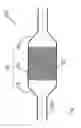
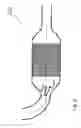
FIG. 1 shows a schematic axially symmetric catalytic converter
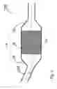
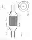
FIG. 2 shows a schematic catalytic converter with angled inlet
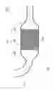
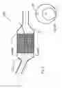
FIG. 3 shows a schematic catalytic converter with curved inlet
FIG. 4 is a view similar to FIG. 1 showing the points of maximum gas velocity at the intersection of the inlet pipe and the can at the lower limit of an operating power range and the upper limit of an operating power range
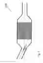
FIG. 5 is a view similar to FIG. 2 showing the points of maximum gas velocity at the intersection of the inlet pipe and the can at the lower limit of the operating power range and the upper limit of the operating power range;
FIG. 6 is a view similar to FIG. 3 showing the points of maximum gas velocity at the intersection of the inlet pipe and the can at the lower limit of the operating power range and the upper limit of the operating power range;
FIG. 7 shows a schematic catalytic converter similar to FIG. 1;
FIG. 7A is a view along section 7A-7A of FIG. 1;
FIG. 8 shows a schematic catalytic converter similar to FIG. 1;
FIG. 8A is a view along section 8A-8A of FIG. 7;
FIG. 9 shows a schematic catalytic converter similar to FIG. 1;
FIG. 9A is a view along section 9A-9A of FIG. 9;
FIG. 10 shows a schematic catalytic converter similar to FIG. 3;
FIG. 10A is a view along section 10A-10A of FIG. 10;
FIGS. 11A-D show inlet back pressure as a function of insulation position for a variety of catalytic converters of the type shown in FIG. 7.
DETAILED DESCRIPTION OF AN EXEMPLARY METHOD
Reference is now made to FIGS. 1-3 which show exemplary catalytic converter systems with which the invention can be usefully deployed:
Each system 22A,22B and 22C includes a can 24 having a cylindrical housing 26 and a pair of diffuser cones 28 and a honeycomb ceramic substrate 30 substantially fully occupying the can 24. The can 24 in system 22A is fed by a cylindrical inlet pipe 32A aligned with the axis of the can 24; in system 22B, the inlet pipe 32B is cylindrical but disposed at angle α to the axis of the can; and in system 22C, the inlet pipe 32C is curved.
Initial steps in the method involve, in respect of any given engine with which the converter is to be used, the determination of the gas direction at the point of maximum gas velocity
-
- when the engine is at the lower limit of the operating power range of concern; and
- when the engine is at the upper limit of the operating power range of concern.
The operating range varies from application to application and in some cases, the range may be defined by a single value. For example, stationary engines, such as generators, are often used at a single power setting, typically 60-80% of designed power, while large freight trucks are operated at a highway cruising power level (20-30% of maximum) for most of their operating time. In the case of common passenger vehicles, the operating range used may be that defined by the typical operating power range, i.e. something between 30 and 80 percent of the maximum power of the engine. The determination of gas direction can be done through measurement, but will normally be done through Computational Fluid Dynamics (CFD) modelling, as the interposition of measurement devices can themselves create flow disruption
In the context of the catalytic converter shown in FIG. 3, there exists a substantial difference between the points of maximum gas velocity Vmax 1, Vmax 2: at lower gas velocities the centrifugal force that the gas molecules are exposed to in the curved pipe is lower and the maximum of the exhaust gas distribution Vmax 1 is closer to the center of the pipe; at higher gas velocities the centrifugal force is stronger and the maximum of the exhaust gas distribution Vmax 2 is closer to the pipe wall, all as shown in FIG. 6.
CFD simulations show, that, for a curved inlet pipe 58 mm in diameter, the difference between the low and high flow positions is 11 mm.
Similar simulations can be done for the catalytic converters of FIGS. 2 and 3, as in some exceptional circumstances, some divergence may occur, but nominally, the point of maximum gas velocity, and both high and low flow conditions, is simply aligned with the centreline of the inlet pipe in both cases, as shown in FIGS. 4 and 5., wherein Vmax 1 and Vmax 1 are defined by the same vector.
With this information in hand, a benchmark is designed. In the benchmark:
-
- an outer tubular outer catalytic zone portion of the substrate surrounds an inner catalytic zone portion of the substrate;
- an insulation material thermally separates the inner catalytic zone and the outer outer catalytic zone;
- an insulation material extends through the substrate and has a uniform cross-section throughout the length of the substrate;
- the uniform cross-section is substantially defined by the intersection of two notional cylinders and the upstream face of the substrate;
- each notional cylinder has: a nominal inner diameter that is between 1.08 and 1.20 of the diameter of the inlet pipe; a thickness of 0.8-4 mm; and an axis aligned with the gas direction at the point of maximum velocity at the intersection of the inlet pipe and the can; and
- one C1 of the notional cylinders is associated with the gas flow at the lower limit of the operating power range and the other C2 of the notional cylinders is associated with the gas flow at the upper limit of the operating power range
The benchmarks for the exemplary systems of FIGS. 4-6 are shown in FIGS. 7-9; in each benchmark, the outer zone is indicated by Zo, the inner zone is indicated by ZI and the insulation layer is indicated by I.
It will be evident that, in the converter of FIG. 1, the notional cylinders C1 and C2 will be coincident and define a cylinder of insulation, as indicated in FIG. 7A; in the converter of FIG. 2, the notional cylinders Ci and C2 will be coincident and will define an ellipse, as indicated in FIG. 8A; and in the converter of FIG. 6, the notional cylinders will be overlapping but not coincident and the insulation is defined by an ovaloid C1C2 that overlaps both projections, as indicated in FIG. 9A.
A variation to FIG. 9 is shown in FIG. 10, wherein the inlet pipe is curved and enters adjacent the sidewall of the housing. The location causes a portion of the ovaloid C1+C2 defined by notional cylinders C1 and C2 to project outside the cylindrical housing 26, such that only an arc lies within the housing 26. To accommodate this notional loss of flow area, the endpoints of the arc are drawn apart from one another, as indicated by arrows A in FIG. 10, until such time as the area encompassed between the arc and the can sidewall is equivalent to the area of the original ovaloid. The same adjustment applies for converters of the type shown in FIG. 8, if the projection lies outside the can.
Without intending to be bound by theory, it is believed that the benchmark will expedite the design of insulated catalytic converter substrates, as this reduce the routine experimentation otherwise required of persons of ordinary skill in the art.
Experimentation has been carried out which supports this conclusion. By way of example, FIGS. 11A-11D show inlet back pressure as a function of insulation position for a variety of catalytic converters of the type shown in FIG. 7. FIG. 11A shows results for a 26 mm radius inlet pipe. FIG. 11B shows results for a 29 mm radius inlet pipe. FIG. 11C shows results for a 32 mm radius inlet pipe. FIG. 11D shows results a 35 mm radius inlet pipe. All other simulation parameters were equal, including exhaust gas temperature and flow rate through the catalytic converter.
Optimum insulation position was defined as that producing the minimum area averaged back pressure in the inlet pipe approx. 30 cm from the catalytic converter can. In each case, the optimum insulation diameter fell within the range of 1.08 and 1.20 of the inlet pipe diameter.
Whereas but a specific embodiment of a method is described, and various specific embodiments of catalytic converter substrates are described, it will be evident that variations are possible.
For example, whereas the examples contemplate usefulness with cylindrical inlet pipes, the methodology would be useful for pipes that departed slightly from the perfectly cylindrical; thus, “cylindrical” in the description and in the claims should be understood as any pipe that appears generally cylindrical in cross section.
Additionally, whereas the terms “inner” and “outer” are used in the specification and claims, it should be understood that in the variation contemplated by FIG. 10, the “outer” zone is that portion indicated as lying above insulation I and the “inner” zone is that portion indicated as lying below insulation I; “inner” and “outer” are references to proximity to the inlet pipe axis.
Accordingly, the invention should be understood as limited only by the accompanying claims, purposively construed.
Claims
1. A method for use with: a combustion engine that has an operating power range having upper and lower limits and a substrate which, in use, substantially fully occupies, but for the diffuser cones, a catalytic converter can to which a cylindrical inlet pipe leads from the engine, the method comprising the steps of:
determining the gas direction at the point of maximum gas velocity at the intersection of the inlet pipe and the can, when the engine is operating at the lower limit of the operating range;
determining the gas direction at the point of maximum gas velocity at the intersection of the inlet pipe and the can, when the engine is operating at the upper limit of the operating range; and
defining a benchmark catalytic converter substrate, wherein, in the benchmark: an outer catalytic zone portion of the substrate surrounds an inner catalytic zone portion of the substrate; an insulation material thermally separates the zones; the insulation material extends through the substrate and has a uniform cross-section throughout the length of the substrate; the uniform cross-section is substantially defined by the intersection of two notional cylinders and the upstream face of the substrate;
wherein each notional cylinder has: a nominal diameter that is between 1.08 and 1.20 of the diameter of the inlet pipe; a thickness of 1-4 mm; and an axis aligned with the gas direction at the point of maximum velocity at the intersection of the inlet pipe and the can; and
one of the notional cylinders is associated with the gas flow at the lower limit of the operating power range and the other of the notional cylinders is associated with the gas flow at the upper limit of the operating power range.
2. An improved catalytic converter substrate, the substrate being of the type used with a combustion engine that has an operating range having upper and lower limits ; and further being of the type used in a catalytic converter can to which a cylindrical inlet pipe leads, wherein the improvement comprises:
an inner catalytic zone portion of the substrate;
an outer catalytic zone portion of the substrate, surrounding the inner catalytic zone;
an insulation material thermally separating the inner and outer zones,
wherein
the insulation material extends through the substrate and has a uniform cross-section throughout the length of the substrate;
the uniform cross-section is substantially defined by the intersection of two notional cylinders and the upstream face of the substrate, each notional cylinder having: a nominal diameter that is between 1.08 and 1.20 of the diameter of the inlet pipe; a thickness of 1-4 mm; and an axis aligned with the gas direction at the point of maximum velocity at the intersection of the inlet pipe and the can; and
one of the cylinders is associated with the gas flow at the lower limit of the operating range and the other of the cylinders is associated with the gas flow at the upper limit of the operating range.
Images & Drawings included:


Sources:
- United States Patent and Trademark Office - verify current appl. status at the USPTO↗
Recent applications in this class:
- » 20250075649 2025-03-06
Partial exhaust gas augmented condensation - » 20210079823 2021-03-18
Plant and air pollution control method - » 20210025304 2021-01-28
Method and system for thermal control of aftertreatment - » 20200263581 2020-08-20
Catalyst temperature estimation device, catalyst temperature estimation system, data analysis device, and control device of internal combustion engine - » 20190316504 2019-10-17
Exhaust gas aftertreatment system for diesel engine and method of detecting abnormal injection - » 20190063284 2019-02-28
Systems and methods for detecting exhaust air leak - » 20180223713 2018-08-09
Method for adjusting the pressure in a pumping system - » 20180030872 2018-02-01
Method for catalyst heating control - » 20170159522 2017-06-08
Method of forcibly regenerating gasoline particulate filter - » 20170089241 2017-03-30
METHOD AND APPARATUS FOR REDUCING EMISSIONS AND/OR REDUCING FRICTION IN AN INTERNAL COMBUSTION ENGINE
Recent applications for this Assignee:
- » 20150337711 2015-11-26
Catalytic converter apparatus - » 20140290218 2014-10-02
Apparatus and method for engine backpressure reduction