Medical headlamp assembly having interchangeable headlamp types with key resistors
US20150289943A1
2015-10-15
14/750,754
2015-06-25
✅ Patent granted
US 9,568,177 B2
2017-02-14
-
-
David V Bruce
Timothy E. Siegel Patent Law, PLLC | Timothy E. Siegel
2035-08-07
Abstract:
A medical headlamp assembly, having a headband subassembly, including an electrical network, including a battery and an electrical jack, and a headlamp mount. Also, an electrical headlamp subassembly, has a mounting element matingly and removably engaged to the headlamp mount, and an electrical plug, matingly and removably engaged to the jack and an electrical headlamp, electrically connected to the plug. Further, the headband subassembly produces an electrical input for the headlamp subassembly and the headband subassembly includes a key resistor, the resistance value of which sets a characteristic of the electrical input.
Assignee:
- RIVERPOINT MEDICAL, LLC 53 🇺🇸 Portland, OR, United States
Applicant:
Interested in similar patents?
Get notified when new applications in this technology area are published.
Classification:
F21V33/00 IPC
Structural combinations of lighting devices with other articles, not otherwise provided for
F21L4/00 » CPC further
Electric lighting devices with self-contained electric batteries or cells
F21W2131/20 » CPC further
Use or application of lighting devices or systems not provided for in codes - Lighting for medical use
F21V21/084 » CPC further
Supporting, suspending, or attaching arrangements for lighting devices ; Hand grips; Devices for easy attachment to any desired place, e.g. clip, clamp, magnet Head fittings
F21V23/02 » CPC main
Arrangement of electric circuit elements in or on lighting devices the elements being transformers, impedances or power supply units, e.g. a transformer with a rectifier
A61B1/0692 » CPC further
Instruments for performing medical examinations of the interior of cavities or tubes of the body by visual or photographical inspection, e.g. endoscopes ; Illuminating arrangements therefor with illuminating arrangements; Endoscope light sources head mounted
A61B90/30 » CPC further
Instruments, implements or accessories specially adapted for surgery or diagnosis and not covered by any of the groups - , e.g. for luxation treatment or for protecting wound edges Devices for illuminating a surgical field, the devices having an interrelation with other surgical devices or with a surgical procedure
A61B2090/309 » CPC further
Instruments, implements or accessories specially adapted for surgery or diagnosis and not covered by any of the groups - , e.g. for luxation treatment or for protecting wound edges; Devices for illuminating a surgical field, the devices having an interrelation with other surgical devices or with a surgical procedure using white LEDs
A61B2090/502 » CPC further
Instruments, implements or accessories specially adapted for surgery or diagnosis and not covered by any of the groups - , e.g. for luxation treatment or for protecting wound edges; Supports for surgical instruments, e.g. articulated arms Headgear, e.g. helmet, spectacles
F21Y2101/00 » CPC further
Point-like light sources
Y10T29/49117 » CPC further
Metal working; Method of mechanical manufacture; Electrical device making Conductor or circuit manufacturing
A61B1/06 IPC
Instruments for performing medical examinations of the interior of cavities or tubes of the body by visual or photographical inspection, e.g. endoscopes ; Illuminating arrangements therefor with illuminating arrangements
F21V21/08 IPC
Supporting, suspending, or attaching arrangements for lighting devices ; Hand grips Devices for easy attachment to any desired place, e.g. clip, clamp, magnet
F21L15/14 » CPC further
Details of kinds solely applicable to the devices covered by groups - concerned with the fitting; Supporting and suspending elements without arrangements for adjustment Clips; Clamps; Head fittings
F21V33/0068 » CPC further
Structural combinations of lighting devices with other articles, not otherwise provided for; Health, life-saving or fire-fighting equipment Medical equipment
Description
RELATED APPLICATIONS
This application is a continuation-in-part of application Ser. No. 14/162,244 filed on Jan. 23, 2014 which is itself a continuation-in-part of application Ser. No. 14/057,351, filed on Oct. 18, 2013, which are incorporated herein by reference as if fully set forth herein, and which, in turn, claims priority from provisional application Ser. No. 61/822,493, filed May 13, 2013, which is also incorporated by reference as if fully set forth herein.
BACKGROUND
Medical headlamp providers have attempted to make a single design that serves a variety of purposes, and in so doing have diminished the capability of such a design to perform any single specialized purpose. For example, many designs feature an adjustable iris, to permit a user to set the beam width of the light produced. Unfortunately, such an iris blocks a good deal of the light, thereby requiring a brighter light source, needing more power.
It is an undesirable expense, however, to purchase a separate head lamp assembly for each purpose that a physicians' office or hospital department may require. It would be desirable to find a way to eliminate at least part of this expense.
SUMMARY
The following embodiments and aspects thereof are described and illustrated in conjunction with systems, tools and methods which are meant to be exemplary and illustrative, not limiting in scope. In various embodiments, one or more of the above-described problems have been reduced or eliminated, while other embodiments are directed to other improvements.
In a first separate aspect, the present invention may take the form of a medical headlamp assembly, having a headband subassembly, including an electrical network, including a battery and an electrical jack, and a headlamp mount. Also, an electrical headlamp subassembly, has a mounting element matingly and removably engaged to the headlamp mount, and an electrical plug, matingly and removably engaged to the jack and an electrical headlamp, electrically connected to the plug. Further, the headband subassembly produces an electrical input for the headlamp subassembly and the headband subassembly includes a key resistor, the resistance value of which sets a characteristic of the electrical input.
In a second separate aspect, the present invention may take the form of a method of switching out a medical headlamp that utilizes a medical headlamp assembly having a headband assembly, including a mounting element, an electrical jack and a power supply assembly electrically connected to the electrical jack. Also, a first headlamp assembly is removably engaged to the mounting element and includes a conductor terminating in a plug that is plugged into the jack, and a first key resistor for setting an electrical input. Also, a second headlamp assembly is removeably engageable to the mounting element and includes a conductor terminating in a plug that is engageable to the jack and a second key resistor for setting the electrical input differently than for the first headlamp. In the method, the first headlamp assembly is removed from the mounting element, the first headlamp plug is unplugged from the jack, the second headlamp is engaged on the mounting element, and the second headlamp plug is plugged into the jack.
In addition to the exemplary aspects and embodiments described above, further aspects and embodiments will become apparent by reference to the drawings and by study of the following detailed descriptions.
BRIEF DESCRIPTION OF THE DRAWINGS
Exemplary embodiments are illustrated in referenced drawings. It is intended that the embodiments and figures disclosed herein are to be considered illustrative rather than restrictive.
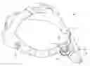
FIG. 1 shows an isometric view of a medical headlamp assembly, having an attached medical headlamp of a first type.
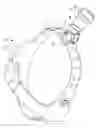
FIG. 2 shows an isometric view of a medical headlamp assembly, having a detached medical headlamp of the first type.
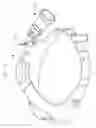
FIG. 3 shows an isometric view of a medical headlamp assembly, having an attached medical headlamp of a second type.
FIG. 4 shows an isometric view of a medical headlamp assembly, having a detached medical headlamp of the second type.
FIG. 5 shows an isometric view of a medical headlamp assembly, having an attached medical headlamp of a third type.
FIG. 6 shows an isometric view of a medical headlamp assembly, having a detached medical headlamp of the third type.
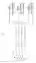
FIG. 7 shows an audio plug and the scheme of use of the poles of the audio plug that is used in a preferred embodiment of the present invention.
FIG. 8 shows a simplified schematic of the electrical network of the medical headlamp assembly of FIGS. 1-6.
FIG. 9 shows a simplified schematic diagram of an alternative preferred electrical network of the of the medical headlamp assembly of FIGS. 1-6.
FIG. 10 shows a simplified schematic diagram of an additional alternative preferred electrical network of the of the medical headlamp assembly of FIGS. 1-6.
DETAILED DESCRIPTION OF THE PREFERRED EMBODIMENTS
Referring to FIGS. 1-6, in a first preferred embodiment a medical headlamp assembly 10 includes a headband 12, supporting a mounting column 14. A low intensity headlamp assembly 16 includes a low intensity headlamp 18, a linkage 20, a slider 22. Also included is an electrical conductor 26 terminating in a four pole audio plug 28, which plugs into a four pole audio jack 30.
As shown in FIG. 2, when a user decides that he would like to remove assembly 16 from mounting column 14, he pulls assembly 16 upwardly to disengage slider 22 from column 14 and unplugs plug 28 from jack 30. He may do this simply to replace a worn out assembly 16, or (referring to FIG. 3) to install an assembly having different characteristics, such as medium intensity assembly 16′, having medium intensity light 18′ and plug 28′ which is plugged into jack 30. Referring to FIGS. 5 and 6, in like manner assembly 16′ can be switched out and assembly 16″, having high intensity light 18″ and plug 28″, can be installed onto slider 22 on column 14, and with plug 28″ plugged into jack 30.
Referring to FIG. 7, although plugs 28, 28′ and 28″ appear identical, each one has a different active pin (longitudinally arranged electrical contact) that is electrically connected to the light emitting diode (not shown) of lamp 18, 18′ or 18″, respectively, and serving as the return, with the current being delivered into lamp 18, 18′ and 18″ in all cases through the ground. Pin 1 of plug 28 serves as the LED return for lamp 18, pin 2 serves as the LED return for lamp 18′, and pin 3 serves as the LED return for lamp 18″. Pin 1, pin 2, and pin 3 of plug 28 connects to pin 2, pin 3 and pin 4 of jack 30, respectively. Pin 1 of jack 30 connects to the ground of plug 28.
Referring to FIG. 8, a DC-to-DC converter 50 acts as a power supply to whichever one of lamps 18, 18′ or 18″ is connected to jack 30. A feedback loop is formed by the output of converter 50 powering the LED line, where all of the current in which flows to the LED return line, and at least a portion of which passes through a current sense resistor R1, which in turn drives the feedback pin FB of converter 50. (The modification of the voltage at feedback pin FB through a voltage increase circuit 54 is described below.) The output of converter 50 increases if the voltage of feedback pin FB is below 0.5 volts and decreases if the voltage of feedback pin FB is above 0.5 volts, thereby setting that voltage at pin FB at 0.5 volts. Accordingly, when the voltage increase circuit 54 is not active, the voltage across resistor R1 is set at 0.5 volts, and accordingly, IR1=R1/0.5 VDC. For the 800 mAmp lamp, for which the return current exits at Pin 2 of the jack 30, a few equations apply:
I R 1 = 800 mAmps - I R 2 . Equation 1 I R 1 = 800 mAmps * ( R 2 + R 3 + R 4 ) R 1 * ( R 2 + R 3 + R 4 + 1 ) . Equation 2
For the 1.1 Amp lamp (from jack 30 pin 3) these equations become:
I R 2 , R 1 = 1.1 mAmps - I R 3 , R 4 . Equation 1 1.1 I R 2 , R 1 = 1.1 mAmps * ( R 3 + R 4 ) ( R 1 + R 2 ) * ( R 3 + R 4 + 1 ) . Equation 2 1.1
For the 1.4 Amp lamp (from jack 30 pin 4) these equations become:
I R 3 , R 2 , R 1 = 1.4 mAmps - I R 4 . Equation 1 1.4 I R 3 , R 2 , R 1 = 1.4 mAmps * ( R 4 ) ( R 1 + R 2 + R 3 ) * ( R 4 + 1 ) . Equation 2 1.4
In addition, for no lamp 18, 18′, or 18″ may the voltage drop through the lamp or the resistive network composed of R1, R2, R3 and R4 exceed a maximum that in one embodiment is about 3.4 volts. In addition, the power consumption of this resistive network must be minimized for all the lamps, leading to low values for all of the resistors, on the order of a little more than an ohm.
The voltage output of the brightness adjust rheostat 40 is fed into a pin of a microprocessor 56, resulting in a periodic waveform having a duty factor that is related to the rheostat output voltage, appearing on an output pin of the microprocessor 56. When the rheostat 40 is moved to a “dim” setting, this causes microprocessor 56 to produce a waveform that causes voltage increase circuitry 54 to amplify the voltage at its input, thereby reducing the current (and voltage) out of the DC-to-DC converter 50, and reducing the current through resistor R5. In an alternative preferred embodiment voltage increase circuitry is set to always amplify its input signal, thereby permitting a lower value for the voltage drop across R1, when the lamp 18, 18′ or 18″ is not being dimmed. This permits a lower value of resistance for R1, and lower power loss through R1 and through the entire resistance network R1, R2, R3 and R4. For dimming positions of rheostat 40, this amplification is increased.
When the brightness adjust knob 40 is set at its maximum, causing a voltage increase circuit 54 (described below) to pass the voltage from a current sense resistor R1, unchanged, then the voltage through the current sense resistor R1 is forced to 0.5 volts by the feedback loop implemented by the converter 50 feedback pin FB (driven directly or indirectly by the current sense resistor R1, and the converter 50 output powering the lamp 18, 18′ or 18″, with the LED return line powering resistor R1).
Referring to FIG. 9, in an alternative embodiment two of the pins of jack 30 are dedicated to connecting a key resistor RK, which together with R1 forms a voltage divider that determines the voltage VCS, which drives amplifier 54, that drives the feedback input of the DC-to-DC Converter 50, which powers lamp 18, 18′, or 18″, having resistance value RL, depending on which is being utilized. When, as noted above in reference to FIG. 8, microprocessor 56 is causing amplifier 54 to simply pass through VCS with unit gain to the feedback pin FB of convertor 50, then, for a specified IL:
IL*RL*R1/(RK+R1)=0.5 Volts; or
IL*RL/0.5=(RK+R1)/R1; or
2*IL*RL=RK/R1+1;
RK=(2*IL*RL−1)*R1
Accordingly, if the designer were to set R1 to 5*105 Ω to draw little current and save energy, RK would be set to 5*105*(1.6RL−1), to set the correct voltage at the lamp 18 input to drive 800 mAmps through lamp 18. For 18′, requiring 1.1 Amps, RK would be set at 5*105*(2.2RL−1), (where RL would reflect the load of lamp 18′, and would be somewhat different than the RL for 18). Finally, for lamp 18″, RK equals 5*105*(2.8RL−1).
Now referring to FIG. 10, which sets the current through RL, if RL is known precisely, then FIG. 9 and FIG. 10 will deliver the exact same current to RL. But if RL differs slightly from an expected value, then the VL2/RL power achieved by fixing the voltage to a specified level that will be achieved by the FIG. 9 electrical network, will differ somewhat from the IL2*RL power achieved by fixing current to a specified level, that will be achieved by the FIG. 10 electrical network. In general, for the FIG. 10 network:
RK=R1/(2*IL−1);
-
- where IL is the specified value of current through the lamp.
For lamp 18, drawing 800 mAmps, RK=(5/3)*R1; for lamp 18′, drawing 1.1 Amps, RK=(5/6)*R1; and for lamp 18″, drawing 1.4 Amps, RK=(5/9)*R1.
In the embodiment of FIG. 9 it is power efficient to set R1 and RK to high values resistance, whereas in the embodiment of FIG. 10, it is efficient to set them to low values of resistance.
While a number of exemplary aspects and embodiments have been discussed above, those possessed of skill in the art will recognize certain modifications, permutations, additions and sub-combinations thereof. It is therefore intended that the following appended claims and claims hereafter introduced are interpreted to include all such modifications, permutations, additions and sub-combinations as are within their true spirit and scope.
Claims
1. A medical headlamp assembly, having:
(a) a headband subassembly, including an electrical network, including a battery and an electrical jack, and a headlamp mount;
(b) an electrical headlamp subassembly, having a mounting element matingly and removably engaged to said headlamp mount, and an electrical plug, matingly and removably engaged to said jack and an electrical headlamp, electrically connected to said plug; and
(c) wherein said headband subassembly produces an electrical input for said headlamp subassembly and said headband subassembly includes a key resistor, the resistance value of which sets a characteristic of said electrical input.
2. The medical headlamp assembly of claim 1, wherein said electrical headlamp subassembly is a first electrical headlamp subassembly having a first key resistor and further including a second electrical headlamp subassembly, having a mounting element capable of removably mating to said headlamp mount and an electrical plug capable of removably mating to said jack and an electrical headlamp, electrically connected to said plug, and further including a second key resistor, having a different value from said first key resistor and which determines said electrical input at a different level than for said first headlamp subassembly.
3. The medical headlamp assembly of claim 1, wherein said resistance of said key resistor determines the voltage of said electrical input.
4. The medical headlamp assembly of claim 1, wherein said resistance of said key resistor determines the current value of said electrical input.
5. A method of switching out a medical headlamp, comprising:
(a) providing a medical headlamp assembly having;
(i) a headband assembly, including a mounting element, an electrical jack and a power supply assembly electrically connected to said electrical jack;
(ii) a first headlamp assembly removably engaged to said mounting element and including a conductor terminating in a plug that is plugged into said jack, and a first key resistor for setting an electrical input; and
(iii) a second headlamp assembly removeably engageable to said mounting element and including a conductor terminating in a plug that is engageable to said jack and a second key resistor for setting said electrical input differently than for said first headlamp;
(b) removing said first headlamp assembly from said mounting element and unplugging said first headlamp plug from said jack; and
(c) mounting said second headlamp on said mounting element and plugging said second headlamp plug into said jack.
6. The method of claim 5, wherein said second headlamp has different illumination characteristics from said first headlamp.
7. The medical headlamp assembly of claim 5, wherein said resistance of said first key resistor and said second key resistor each determine the voltage of said electrical input.
8. The medical headlamp assembly of claim 5, wherein said resistance of said first key resistor and said second key resistor, each determine the current value of said electrical input.
Images & Drawings included:


Sources:
- United States Patent and Trademark Office - verify current appl. status at the USPTO↗
Recent applications in this class:
- » 20160081755 2016-03-24
Automatic machine settings for customized refractive surgery - » 20160067003 2016-03-10
Proximal-end securement of a minimally invasive working channel - » 20160058518 2016-03-03
Medical accessory holder - » 20160038240 2016-02-11
IRRIGATION EQUIPMENT LIFTING APPARATUS - » 20160030124 2016-02-04
SURGICAL TOOL HOLDING DEVICE, ENDOSCOPE, AND MEDICAL SYSTEM - » 20160000514 2016-01-07
SURGICAL VISION AND SENSOR SYSTEM - » 20150366627 2015-12-24
Rotatable connection having rotational angle limitation - » 20150342692 2015-12-03
Stand for a medical-optical instrument - » 20150335389 2015-11-26
SURGICAL TENSION SETTING SYSTEM - » 20150297305 2015-10-22
Medical holding arm
Recent applications for this Assignee:
- » 20230054902 2023-02-23
Soft button assembly and procedure - » 20210353280 2021-11-18
Soft Suture Anchor - » 20210259676 2021-08-26
Method of forming a suture-button-graft combination and facilitating construct - » 20210137515 2021-05-13
Method of performing a tendon replacement - » 20210068942 2021-03-11
Method of making a continuous loop - » 20200405001 2020-12-31
Headband having suspended comfort element - » 20200337130 2020-10-22
Color Tunable Medical Headlamp Bezel - » 20200229891 2020-07-23
Headlamp assembly having comfort element - » 20200109844 2020-04-09
Headlamp assembly - » 20200107828 2020-04-09
Suture and soft anchor assembly and method of making the same