Apparatus and method for preparing a sample from components internal to a tire
US20150290723A1
2015-10-15
14/439,994
2013-12-18
✅ Patent granted
US 9,700,946 B2
2017-07-11
WO; PCT/US2013/076174; 20131218
WO; WO2014/100208; 20140626
Natalie Huls | Monica S Young
Meredith E. Hooker | John M. Skeriotis
2034-04-13
Abstract:
Provided is a method for preparing a test sample comprising, providing a CNC machine; providing a cured tire comprising, a tire component at least partially covered by an external component, or a tire component at least partially covered by an internal component; and using the CNC machine to separate the tire component from the cured tire by either removing part of the external component, or removing part of the internal component.
Assignee:
- Bridgestone Americas Tire Operations, LLC 411 🇺🇸 Nashville, TN, United States
Applicant:
Interested in similar patents?
Get notified when new applications in this technology area are published.
Classification:
B23C3/00 » CPC main
Milling particular work; Special milling operations; Machines therefor
G01N1/04 » CPC further
Sampling; Preparing specimens for investigation; Devices for withdrawing samples in the solid state, e.g. by cutting
G01M17/02 » CPC further
Testing of vehicles; Wheeled or endless-tracked vehicles Tyres
G01N2203/0298 » CPC further
Investigating strength properties of solid materials by application of mechanical stress; Details not specific for a particular testing method; Specifications of the specimen Manufacturing or preparing specimens
Description
TECHNICAL FIELD
The present subject matter relates generally to a tire testing. More, specifically, the present subject matter relates to an apparatus and method for preparing a sample from components internal to a tire.
BACKGROUND
It is sometimes desirable to create test samples from internal components of a tire. Creation of test samples often requires the use of hand tools and user-guided power tools to extract the internal components of a tire. The use of hand tools and user-guided power tools to extract the internal components of a tire can be imprecise and can present safety issue.
Computer numerical control (CNC) machine tools and CNC controlled machining can be more precise than and/or safer than the use of hand tools and user-guided power tools.
It remains desirable to develop methods and apparatus for the create test samples from internal components of a tire to make precision cuts to the components of a tire.
SUMMARY
Provided is a method for preparing a test sample comprising, providing a CNC machine; providing a cured tire comprising, a tire component at least partially covered by an external component, or a tire component at least partially covered by an internal component; and using the CNC machine to separate the tire component from the cured tire by either removing part of the external component, or removing part of the internal component.
BRIEF DESCRIPTION OF THE DRAWINGS
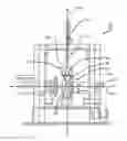
FIG. 1 is a view of a first embodiment of a CNC machine.
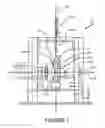
FIG. 2 is a portion of a cross-section of a tire tread.
FIG. 3 is a portion of a cross-section of a tire tread.
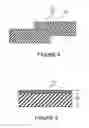
FIG. 4 is a portion of a cross-section of a tire tread.
FIG. 5 is a portion of a cross-section of a tire tread.
DETAILED DESCRIPTION
Reference will be made to the drawings, FIGS. 1-5, wherein the showings are only for purposes of illustrating certain embodiments of an apparatus and method for preparing a sample from components internal to a tire.
Referring now to FIG. 1, an apparatus 110 adapted to prepare an internal tire component sample may comprise a tire engagement component 120, and a CNC machine 130. The CNC machine 130 may be engaged with the tire engagement component 120. In the non-limiting implementations shown in FIG. 1, the CNC machine 130 is engaged with the tire engagement component 120 through a frame 140. The frame 140 may be adapted to engage both the CNC machine 130 and the tire engagement component 120 in such a manner as to substantially positively locate the CNC machine 130 with respect to the tire engagement component 120. As used herein, the term substantially positively locate means to provide a positive location having an error less than that of the desired machining process; the positive location error typically being less 0.001 inches. In other non-limiting implementations, the CNC machine 130 may be engaged with the tire engagement component 120 using means acceptable to good engineering judgment.
The tire engagement component 120 may be any sort of apparatus adapted to provide engagement between the CNC machine 130 and the tire 160. In the implementation shown in FIG. 1 the tire engagement component 120 is an apparatus adapted to simultaneously engage the tire 160, and engage, indirectly through frame 140, the CNC machine 130. In certain implementations, the tire engagement component 120 may comprise adaptations such as a motor, rotatable shaft 122, or other apparatus to permit the tire 160 to be selectably rotated or moved with respect to the CNC machine 130 while the tire 160 is engaged with the tire engagement component 120. In certain implementations, the tire engagement component 120 holds the tire 160 in a substantially fixed position and orientation with respect to the CNC machine 130 while the tire 160 is engaged with the tire engagement component 120.
In certain implementations, the tire engagement component 120 may comprise or be adapted to engage with conventional components typically adapted for the engagement of a tire 160 with a vehicle (not shown) or to provide selectable freedom of motion or orientation between a tire 160 with a vehicle (not shown). These conventional components may include, but are not limited to, a wheel 124, a lug nut (not shown), a hub 126, a lug bolt (not shown), and a brake (not shown). In certain implementations, the tire engagement component 120 may comprise or be adapted to engage with conventional components typically adapted for the test testing such as, without limitation, a digital encoder (not shown), and a load cell (not shown).
The CNC machine 130 may be any sort of computer numerical control machine tool. As used herein, CNC machining comprises 5 axis machining, 4 axis machining, and 3 axis machining. The CNC machine 130 may comprise a tool spindle 132 that may be moved with respect to an object to be machined, such as, without limitation, a tire 160. A tool spindle 132 that may be moved with respect to an object to be machined along an X axis 112, a Y axis perpendicular to the X-axis (not shown), and along a Z-axis 116 mutually perpendicular to the X-axis 112 and the Y-axis (not shown). In certain implementations, the tool spindle 132 may be adapted to translate along and rotate about Cartesian coordinates. In certain implementations, the tool spindle 132 may be adapted to translate along and rotate about cylindrical coordinates. In certain implementations, the tool spindle 132 may be adapted to translate along and rotate about spherical coordinates. In the non-limiting implementation shown in FIG. 1, the position of the tool spindle 132 may be driven by motors through a set of step-down gears, by direct-drive stepper motor, or servo motors. While in typical commercial CNC machines closed-loop controls are standard, in some implementations of the present subject matter, open-loop control may also be acceptable if the forces applied are kept small and speeds are not large.
A CNC machine 130 may be adapted to perform any of a large variety of processes including but not limited to milling, punching, plasma cutting, and grinding.
Tire 160 may be any sort of tire. The tire 160 may be pneumatic, non-pneumatic, run-flat, radial, or bias. The tire 160 may be a passenger tire, a light truck tire, a truck or bus tire, an agricultural tire, or other sort of tire. The tire 160 may be a cured tire, or a uncured tire. In the non-limiting implementations shown in FIG. 1, tire 160 is a pneumatic tire mounted to the tire engagement component 120 and inflated to some desired pressure.
As shown in the non-limiting embodiment shown in FIG. 1, the tire 160 may comprise an external component 162 and an internal component 163. The non-limiting embodiment shown in FIG. 2, is a cross-section of a tire 160 showing the tire components 161 thereof. In the non-limiting embodiment shown in FIG. 2, the tire components 161 comprise tread 164 which covers subtread 165 which covers a third compound 166 which covers a belt package 167 which covers a body ply compound with fabric 168 which covers an innerliner 169. As shown in FIG. 2, tread 164 is the most external of the components while the innerliner 169 is the most internal of the components. In some embodiments a component that covers another component may provide full coverage, and in others it may provide only partial coverage.
In order to prepare an internal tire component sample, it may be desirable to section out an individual tire component 161 or a sub-set of tire components 161. To section out a desired component 161 is to remove all or substantially all of the engaged components or materials that are not the desired component 161. Similarly, to section out a desired sub-set of tire components 161 is to remove all or substantially all of the engaged components or materials that are not the desired sub-set of tire components 161. Sectioning out a desired tire component 161 or a sub-set of tire components 161 requires a material removal process such as, without limitation cutting or milling to remove the engaged components or materials that are not the desired component 161 or a sub-set of tire components 161. A CNC machine may be usable for very precise material removal processes so as to be usable to prepare an internal tire component sample of a very specific geometry.
As shown in the non-limiting embodiment shown in FIGS. 2 and 3, the tire components 161, tread 164, subtread 165, third compound 166, belt package 167, body ply compound with fabric 168, and innerliner 169, may follow a complex path, that is a path that is undulating or otherwise not straight, either in the plane of the cross-section shown in FIG. 2, transverse to the plane of the cross-section shown in FIG. 2, or both. In order to section out a tire component 161 that follows a complex path, the cutting tool must be able to follow a similarly complex path defining a very precise geometry. Hand cutting methods are sometime not sufficiently precise for such purposes.
In the non-limiting embodiment shown in FIG. 4, an internal tire component sample section 410 may be formed by sectioning out tire components 161, such as, without limitation, belt package 167. The internal tire component sample section 410 is defined by a precise geometry identified by the outer surface 420 of the sample section 410.
FIG. 5 shows a non-limiting embodiment of a common test sample 510 of a part of a tire component 161 comprising rubber with a nylon cap. The width dimension 520 of the test sample 510 is 0.5 inch. Cutting test sample 510 by hand with the desired precision would be very difficult, in part, because test sample 510 is so small.
As is noted above, a CNC machine may be usable to prepare an internal tire component sample by section out a tire component 161 as defined by a precise geometry. That is, it is possible to use CNC technology, such as programs, vision systems, and other conventional CNC inputs, in order to obtain required material removal lengths and depths, or to otherwise extract desired individual compounds or components with great precision. Cutting test sample 510 by use of a CNC machine 130 with the desired precision would be very simple even though the test sample 510 is so small.
Accordingly, it may be desirable to use an apparatus 110 comprising a CNC machine 130 to create a test sample 510 from tire components 161 of a tire 160. A test sample 510 of tire components 161 of a tire 160, comprising an external component 162 that at least partially covers tire components 161 or an internal component 163 that at least partially covers tire components 161, may be prepared by providing a CNC machine 130; providing a tire 160; and using the CNC machine 130 to separate the tire components 161 from the tire 160 by remove part of the external component 162 or part of the internal component 163.
While the apparatus and method for preparing a sample from components internal to a tire has been described above in connection with certain embodiments, it is to be understood that other embodiments may be used or modifications and additions may be made to the described embodiments for performing the same function of the apparatus and method for preparing a sample from components internal to a tire without deviating therefrom. Further, the apparatus and method for preparing a sample from components internal to a tire may include embodiments disclosed but not described in exacting detail. Further, all embodiments disclosed are not necessarily in the alternative, as various embodiments may be combined to provide the desired characteristics. Variations can be made by one having ordinary skill in the art without departing from the spirit and scope of the apparatus and method for preparing a sample from components internal to a tire. Therefore, the apparatus and method for preparing a sample from components internal to a tire should not be limited to any single embodiment, but rather construed in breadth and scope in accordance with the recitation of the attached claims.
Claims
What is claimed is:1. An apparatus for preparing a tire test sample comprising:
a tire;
wherein the apparatus is characterized by:
a CNC machine comprising a cutting tool; and,
wherein the CNC machine is adapted to use the cutting tool to remove a tire test sample from the tire before the tire test sample is tested.
2. The apparatus of claim 1 further comprising:
a tire engagement component that engages the tire to the CNC machine; and,
wherein the tire engagement component is adapted to rotate the tire with respect to the CNC machine before the CNC machine removes the tire test sample from the tire.
3. The apparatus of claim 2 wherein the tire engagement component holds the tire in a substantially fixed position and orientation with respect to the CNC machine while the CNC machine removes the tire test sample from the tire.
4. The apparatus of claim 1 wherein the CNC machine comprises a tool spindle that:
holds the cutting tool; and,
is movable with respect to the tire.
5. The apparatus of claim 1 wherein:
the tire is a cured pneumatic tire mounted to a wheel; and,
a tire engagement component engages the tire to the CNC machine through the wheel.
6. The apparatus of claim 1 wherein:
the tire is a cured pneumatic tire having an external component and an internal component; and,
the CNC machine removes the tire test sample from at least one of the external component and the internal component.
7. The apparatus of claim 6 wherein:
the tire test sample includes at least a portion of a belt package; and, the cutting tool follows an undulating path to remove the tire test sample from the tire.
8. The apparatus of claim 7 wherein the CNC machine separates the tire test sample with a width of approximately 0.5 inches.
9. A method for preparing a tire test sample comprising the steps of:
(A) providing a tire;
(B) obtaining a tire test sample from the tire; and,
(C) testing the tire test sample;
wherein the apparatus is characterized by:
(D) providing a CNC machine comprising a cutting tool; and,
wherein step (B) comprises the step of: using the cutting tool on the CNC machine to remove the tire test sample from the tire.
10. The method of claim 9 wherein:
the method further comprises the step of: providing a tire engagement component that engages the tire to the CNC machine; and,
prior to step (B) the method comprises the step of: rotating the tire with respect to the CNC machine using the tire engagement component.
11. The method of claim 10 wherein during step (B) the tire engagement component holds the tire in a substantially fixed position and orientation with respect to the CNC machine.
12. The method of claim 9 wherein:
step (D) comprises the step of: providing the CNC machine with a tool spindle that holds the cutting tool; and,
prior to step (B) the method comprises the step of moving the tool spindle and cutting tool with respect to the tire.
13. The method of claim 9 wherein:
step (A) comprises the step of: providing the tire to be a cured pneumatic tire including a belt package; and,
step (B) comprises the step of: removing the tire test sample to include at least a portion of the belt package.
14. The method of claim 9 wherein step (B) comprises the step of:
using the cutting tool to follow an undulating path to remove the tire test sample from the tire.
15. The method of claim 9 wherein:
step (A) comprises the step of: providing the tire to be a cured pneumatic tire mounted to a wheel;
the method further comprises the step of: providing a tire engagement component that engages the tire to the CNC machine; and,
prior to step (B) the method comprises the step of: engaging the tire engagement component to the tire through the wheel.
Images & Drawings included:

Sources:
- United States Patent and Trademark Office - verify current appl. status at the USPTO↗
Recent applications in this class:
- » 20240316658 2024-09-26
ULTRA-PRECISION MACHINING METHOD - » 20220266355 2022-08-25
Expandable vacuum chamber and method for producing an expandable vacuum chamber - » 20210299765 2021-09-30
Method for machining thin plates and elastic joints particularly for monolithic mechanical oscillators - » 20190210121 2019-07-11
Method for machining the interior of a brake caliper of a disc brake - » 20180104749 2018-04-19
Method for machining flat surfaces of a workpiece - » 20160250694 2016-09-01
Milling device for optical lens production with two milling stations and method of use - » 20160199922 2016-07-14
Method, System, Computer Program And A Computer Program Product For Measuring Objects - » 20160107246 2016-04-21
Method and apparatus for creating a starting hole for milling in a surface of a workpiece by a CNC milling machine - » 20160101474 2016-04-14
Spiral toolpaths for high-speed machining of polygonal pockets - » 20140331732 2014-11-13
Apparatus and method for processing anode plate for electrolysis
Recent applications for this Assignee:
- » 20250230302 2025-07-17
Tire Tread Rubber Composition And Related Methods - » 20250196543 2025-06-19
DIRECTIONAL INTERLOCKING SIPE AND/OR SLOT WITH CHAMFER - » 20250135808 2025-05-01
TIRE HAVING CANTILEVERED SIDEWALL SHAPE AND FLEXIBLE SUPPORT RING STRUCTURE - » 20250101208 2025-03-27
RUBBER FORMULATIONS COMPRISING A STATISTICAL COPOLYMER COMPRISING VINYLBENZOCYCLOBUTANE - » 20250101161 2025-03-27
STATISTICAL COPOLYMERS COMPRISING VINYLBENZOCYCLOBUTANE AND METHODS OF MAKING THE SAME - » 20250065676 2025-02-27
SYSTEM, METHOD, AND APPARATUS FOR MAINTAINING A TIRE INFLATION PRESSURE - » 20250050689 2025-02-13
BI-DIRECTIONAL INTERLOCKING SIPE AND SLOT COMBINATION - » 20250010663 2025-01-09
Tire Tread Rubber Composition - » 20240424836 2024-12-26
BI-DIRECTIONAL SIPE AND/OR SLOT - » 20240408922 2024-12-12
TIRE ELECTRONICS ASSEMBLY