Machine arrangement
US20150292966A1
2015-10-15
14/406,948
2013-06-12
✅ Patent granted
US 9,746,387 B2
2017-08-29
WO; PCT/EP2013/062145; 20130612
WO; WO2013/186258; 20131219
Alan B Waits
Bryan Peckjian | SKF USA Inc. Patent Dept.
2033-08-09
Abstract:
A machine arrangement, including at least one bearing ring, wherein a glass fiber is connected with the machine arrangement. To allow a proper measurement of stresses, even at curved surfaces of the machine arrangement as it is typical in the case of bearing rings, the connection between the glass fiber and the machine arrangement is established by a glass material. The glass material is connected by material bonding with the machine arrangement as well as with the glass fiber.
Inventors:
- Hendrik Anne Mol 30 🇳🇱 Sleeuwijk, Netherlands
- John F. van de Sanden 6 🇳🇱 Nieuwegein, Netherlands
- Hongyu Yang 4 🇳🇱 Houten, Netherlands
Assignee:
- Aktiebolaget SKF 1,363 🇸🇪 Gothenburg, Sweden
Applicant:
Interested in similar patents?
Get notified when new applications in this technology area are published.
Classification:
G01L1/246 » CPC main
Measuring force or stress, in general by measuring variations of optical properties of material when it is stressed, e.g. by photoelastic stress analysis using infra-red, visible light, ultra-violet the material being an optical fibre using integrated gratings, e.g. Bragg gratings
G01L1/24 IPC
Measuring force or stress, in general by measuring variations of optical properties of material when it is stressed, e.g. by photoelastic stress analysis using infra-red, visible light, ultra-violet
G01L5/0009 » CPC further
Apparatus for, or methods of, measuring force, work, mechanical power, or torque, specially adapted for specific purposes Force sensors associated with a bearing
G01M11/086 » CPC further
Testing of optical apparatus; Testing structures by optical methods not otherwise provided for; Testing mechanical properties by using an optical fiber in contact with the device under test [DUT] Details about the embedment of the optical fiber within the DUT
F16C41/00 » CPC further
Other accessories, e.g. devices integrated in the bearing not relating to the bearing function as such
G01M11/08 IPC
Testing of optical apparatus; Testing structures by optical methods not otherwise provided for Testing mechanical properties
G01L5/00 IPC
Apparatus for, or methods of, measuring force, work, mechanical power, or torque, specially adapted for specific purposes
F16C2226/36 » CPC further
Joining parts; Fastening; Assembling or mounting parts; Material joints by welding
F16C33/586 » CPC further
Parts of bearings; Special methods for making bearings or parts thereof; Parts of ball or roller bearings; Raceways; Race rings; Details of specific parts of races outside the space between the races, e.g. end faces or bore of inner ring
C03C27/044 » CPC further
Joining pieces of glass to pieces of other inorganic material; Joining glass to glass other than by fusing; Joining glass to metal by means of an interlayer consisting of a combination of materials selected from glass, glass-ceramic or ceramic material with metals, metal oxides or metal salts of glass, glass-ceramic or ceramic material only
F16C33/58 IPC
Parts of bearings; Special methods for making bearings or parts thereof; Parts of ball or roller bearings Raceways; Race rings
F16C19/52 » CPC further
Bearings with rolling contact, for exclusively rotary movement with devices affected by abnormal or undesired conditions
F16C2233/00 » CPC further
Monitoring condition, e.g. temperature, load, vibration
C03C27/04 IPC
Joining pieces of glass to pieces of other inorganic material; Joining glass to glass other than by fusing Joining glass to metal by means of an interlayer
G01M13/04 » CPC further
Testing of machine parts Bearings
Description
CROSS REFERENCE TO RELATED APPLICATIONS
This is a National Stage Application claiming the benefit of International Application Number PCT/EP2013/062145 filed on 12 Jun. 2013, which claims the benefit of European Patent Application Serial Number PCT/EP2012/061407 filed on 15 Jun. 2012, both of which are incorporated herein by reference in their entireties.
TECHNICAL FIELD
The invention relates to a machine arrangement, comprising or being at least one bearing ring, wherein a glass fiber is connected with the machine arrangement.
BACKGROUND
It is known in the art to equip a machine part of this kind with a glass fiber element to allow the measurement of different physical parameters. By doing so, a survey of the parameters becomes possible by using the fiber Bragg grating (FBG) method. By this method temperatures as well as strains of the machine arrangement can be monitored. An example of an arrangement of the generic kind is disclosed in US 2010/0158434 A1.
For doing so it is necessary to connect a glass fiber with the component. For surveying temperatures it is essential that a thermal coupling between the glass fiber and the machine arrangement is established. For monitoring strains it is necessary to mechanically connect the glass fiber with the component to be monitored.
Specifically in the latter case problems arise because the glass fiber is normally equipped with a plurality of coaxially arranged cover layers. A typical construction employs a cladding arranged around the glass fiber (core) itself; the cladding is coated by a coating layer. Then, strengthening fibers (made e. g. from aramid) are arranged at the outer circumference of the coating. Finally the strengthening fibers are cased by a hollow cylindrical cable jacket.
When a glass fiber element of this type is connected with the component a certain elasticity is immanent between the glass core and the component. Thus, specifically the measurement of strains is problematic due to the elasticity. This is specifically a problem when the component is not even or flat but if it has a spherical shape. This is typical in the case of a part of a bearing, specifically of a roller bearing.
US 2002/0118908 A1 shows the connection of an axial end of a glass fiber with substrate by means of glass material.
It is an object of the present invention to propose a machine arrangement of the above mentioned kind which is designed in such a manner that a contact is established between the glass fiber core and the component which is as stiff as possible. By doing so it is aimed to monitor physical properties, especially of strains in the component, with a high degree of precision. Thus, specifically a proper measurement of stresses should become possible even at curved surfaces of the machine arrangement as it is typical in the case of bearing rings.
SUMMARY OF THE INVENTION
A solution according to the invention is characterized in that the connection between the glass fiber and the machine arrangement is established by a glass material which glass material is connected by material bonding with the machine arrangement as well as with the glass fiber, wherein the glass fiber is connected with the machine arrangement by encasing the whole circumference of the glass fiber with the glass material along at least a part of the longitudinal axis of the glass fiber.
The glass fiber is basically free from any layer as described above. An exception can be that the glass fiber is encased by a reflective cover material to ensure the conduction of light through the glass fiber. Here, a specific solution suggests that the reflective cover material is a second glass material, wherein the refractive index of the glass fiber is different from the refractive index of the second glass material. Insofar, the glass fiber has then some kind of cladding to keep that light in the glass fiber. This cladding is then fused to the substrate.
The material bonded connection between the glass material and the machine arrangement can be established by a welding process using the glass material.
The material bonded connection between the glass material and the glass fiber can also be established by a welding or melting process using the glass material.
The glass material can have at least partially a thickness measured in the direction perpendicular to the longitudinal axis of the glass fiber of at least 0.3 mm, preferably of at least 0.5 mm.
The glass fiber can be arranged on a curved surface of the machine arrangement, especially on a cylindrical surface of a bearing ring.
Thereby, the glass fiber can be attached to a cylindrical surface of the machine arrangement. Also, it is possible to locate the glass fiber in a groove which is machined for the glass fiber into the machine arrangement.
By the proposed design a stiff and direct connection is established between the glass fiber and the component to be monitored so that physical parameters—especially temperatures and strains—can be detected in a precise way.
BRIEF DESCRIPTION OF THE DRAWINGS
The drawings show an embodiment of the invention.
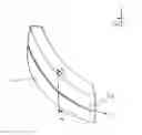
FIG. 1 shows in a perspective view a section of a outer bearing ring of a roller bearing, on which a glass fiber is fixed and
FIG. 2 shows the cross section A-A according to FIG. 1.
DETAILED DESCRIPTION OF THE INVENTION
In FIG. 1 a machine arrangement 1 being an outer bearing ring of a roller bearing is shown. The bearing ring 1 has an outer spherical surface which is to be monitored with respect to strains which act in the machine part. The survey of those strains is carried out by the fiber Bragg grating (FBG) method which is known as such. Reference is made e.g. to U.S. Pat. No. 6,923,048 B2 where this technology is explained in more detail.
For doing so a glass fiber 2 is securely fixed on the spherical, i.e. cylindrical outer circumference of the bearing ring 1. The glass fiber 2 has a longitudinal direction L which extends in the circumferential direction of the bearing ring 1.
Details concerning the fixation of the glass fiber 2 at the bearing ring 1 can be seen from FIG. 2.
Here, it can be seen that the glass fiber 2 is basically the pure glass element—possibly covered only by a reflective coating to ensure proper light conduction within the glass fiber—which is then connected with the bearing ring 2 by means of glass material 3.
Thus, a material bonding is established between the glass fiber 2 and the machine part 1 to be monitored. This means, all strains in the machine part 1 are directly transferred into the glass fiber 2. Thus, the precondition is assured for a precise measurement of physical parameters of the machine part 1.
REFERENCE NUMERALS
- 1 Machine arrangement (bearing ring)
- 2 Glass fiber
- 3 Glass material
- L Longitudinal axis
Claims
1. A machine arrangement, comprising or being at least one bearing ring, wherein a glass fiber is connected with the machine arrangement,
wherein the connection between the glass fiber and the machine arrangement is established by a glass material wherein the glass material is connected by material bonding with the machine arrangement as well as with the glass fiber,
wherein the glass fiber is connected with the machine arrangement by encasing the whole circumference of the glass fiber with the glass material along at least a part of the longitudinal axis of the glass fiber.
2. The machine arrangement according to claim 1, wherein the glass fiber is encased by a reflective cover material.
3. The machine arrangement according to claim 2, wherein the reflective cover material is a second glass material, wherein the refractive index of the glass fiber is different from the refractive index of the second glass material.
4. The machine arrangement according to claim 1, wherein the material bonded connection between the glass material and the machine arrangement is established by a welding process using the glass material.
5. The machine arrangement according to claim 1, wherein the material bonded connection between the glass material and the glass fiber is established by a welding or melting process using the glass material.
6. The machine arrangement according to claim 1, wherein the glass material has at least partially a thickness measured in the direction perpendicular to the longitudinal axis of the glass fiber of at least 0.3 mm.
7. The machine arrangement according to claim 1, wherein the glass fiber is arranged on a curved surface of the machine arrangement.
8. The machine arrangement according to claim 7, wherein the curved surface of the machine arrangement is a cylindrical surface of a bearing ring.
9. The machine arrangement according to claim 1, wherein the glass material has at least partially a thickness measured in the direction perpendicular to the longitudinal axis of the glass fiber of at least 0.5 mm.
Images & Drawings included:


Sources:
- United States Patent and Trademark Office - verify current appl. status at the USPTO↗
Similar patent applications:
- » 20080236578
ANAESTHESIA MACHINE ARRANGEMENT AND A METHOD IN CONNECTION WITH AN ANAESTHESIA MACHINE ARRANGEMENT - » 20080236583
Anaesthesia machine arrangement and a method in connection with an anaesthesia machine arrangement - » 20160301281
Electric machine arrangement, motor vehicle gearbox and method for producing an electric machine arrangement - » 20230278093
Machine handling device and method for handling an electrically conductive sheet-metal workpiece and also machine arrangement for machining sheet metal - » 20100264121
Machine arrangement for machining bar-like workpieces having a device for workpiece support - » 20140103233
Hydraulic valve arrangement and hydraulic machine arrangement having a valve arrangement of this kind - » 20180118397
WRAPPING MACHINE PRINTER ARRANGEMENT AND WRAPPING MACHINE FILM CUTTER ARRANGEMENT - » 20170215632
Beverage preparation machine arranged to share capsule image and machine operation data - » 20190345694
Hydraulic control arrangement for an arrangement of mobile machines, and arrangement of mobile machines - » 20200087013
Wrapping machine printer arrangement and wrapping machine film cutter arrangement
Recent applications in this class:
- » 20250258048 2025-08-14
MULTI-AXIS FIBER BRAGG GRATING SENSORS AND SYSTEMS - » 20250224287 2025-07-10
FIBER BRAGG GRATING FOR MEASURING INTERNAL METAL LOSS - » 20250164330 2025-05-22
PLATFORM WITH TRENCH FOR OPTICAL FIBER WITH SENSORS - » 20250164329 2025-05-22
SYSTEMS, DEVICES, AND METHODS FOR MINIATURIZATION OF FIBER BRAGG GRATING INTERROGATION FOR INTEGRATION INTO IMPLANTABLE DEVICES - » 20250137858 2025-05-01
MEASUREMENT SYSTEM COMPRISING AN OPTICAL FIBER PROVIDED WITH AT LEAST ONE BRAGG GRATING FOR MEASURING DYNAMIC DEFORMATION, AIRCRAFT AND METHOD - » 20250130125 2025-04-24
Optical Sensor System - » 20250102382 2025-03-27
SYSTEMS, DEVICES AND METHODS FOR MONITORING SUPPORT PLATFORM STRUCTURAL CONDITIONS - » 20250102381 2025-03-27
Measuring device and method for producing and using the same - » 20250060263 2025-02-20
MEASURING METHOD FOR DETECTING A MECHANICAL FORCE ACTING ON AN OBJECT USING A FIBER OPTIC SENSOR UNIT - » 20250035496 2025-01-30
OPTICAL FIBER SYSTEM TO DETERMINE AT LEAST ONE PHYSICAL PARAMETER AND METHOD TO DETERMINE AT LEAST ONE PHYSICAL PARAMETER USING AN OPTICAL FIBER SYSTEM
Recent applications for this Assignee:
- » 20250243936 2025-07-31
SEAL WITH AXIAL AIR VENTS - » 20240405632 2024-12-05
OPTIMIZED BALL BEARING AND METHOD OF DESIGNING AN OPTIMIZED BALL BEARING - » 20240384753 2024-11-21
BEARING ASSEMBLY - » 20240352971 2024-10-24
Rolling-element bearing cage, rolling-element bearing, vehicle, and method for assembling a rolling-element bearing cage - » 20240280141 2024-08-22
BEARING UNIT - » 20240271701 2024-08-15
Self-retaining lip seal - » 20240264656 2024-08-08
SENSOR AND ASSOCIATED METHOD - » 20240255321 2024-08-01
Sensor guard - » 20240200607 2024-06-20
ROLLING-ELEMENT BEARING WITH SEALS AND PURGING CHANNEL - » 20240200600 2024-06-20
Arc-shaped segment for assembling a segmented cage, cage and bearing