Securing device for golf having removable studs
US20150297968A1
2015-10-22
14/648,044
2013-11-05
✅ Patent granted
US 9,833,679 B2
2017-12-05
WO; PCT/MX2013/000132; 20131105
WO; WO2014/084703; 20140605
Nini Legesse
Edwin S. Flores | Chalker Flores LLP
2033-11-29
Abstract:
The golf shoe holder with dismountable threaded cleats prevents the supporting foot of a person from moving when attempting to hit the golf ball with a golf club. This is achieved as the holder has two holes with different diameters: the large diameter is to be held between the cleats and the golf shoe sole, by means of the threads that both parts have, and the small diameter is where it holds on to the grass by means of a tee.
Assignee:
- Roberto Serrano Cruz 1 🇲🇽 Atizapan, Mexico
Applicant:
Interested in similar patents?
Get notified when new applications in this technology area are published.
Classification:
A63B69/0057 » CPC main
Training appliances or apparatus for special sports Means for physically limiting movements of body parts
A63B69/3608 » CPC further
Training appliances or apparatus for special sports for golf Attachments on the body, e.g. for measuring, aligning, restraining
A43C15/161 » CPC further
Non-skid devices or attachments; Studs or cleats for football or like boots characterised by the attachment to the sole
A63B69/0059 » CPC further
Training appliances or apparatus for special sports; Means for physically limiting movements of body parts worn by the user
A63B69/3667 » CPC further
Training appliances or apparatus for special sports for golf Golf stance aids, e.g. means for positioning a golfer's feet
A63B2071/0694 » CPC further
Games or sports accessories not covered in groups -; Indicating or scoring devices for games or players, or for other sports activities Visual indication, e.g. Indicia
A63B69/36 IPC
Training appliances or apparatus for special sports for golf
A63B69/00 IPC
Training appliances or apparatus for special sports
A63B57/00 » CPC further
Golfing accessories
A43D999/00 » CPC further
Subject matter not provided for in other groups of this subclass
A43C15/16 IPC
Non-skid devices or attachments Studs or cleats for football or like boots
A63B57/10 » CPC further
Golfing accessories Golf tees
A63B71/06 IPC
Games or sports accessories not covered in groups - Indicating or scoring devices for games or players, or for other sports activities
A63B2208/0204 » CPC further
Characteristics or parameters related to the user or player posture Standing on the feet
Description
This invention refers to a shoe holder that specifically serves to prevent the foot that provides support from moving when attempting to hit the ball with the golf club; the supporting foot is determined as follows: when a person is right handed, it is the left foot, and when the person is left handed, it is the right foot.
INVENTION BACKGROUND
Within the field of golf, it is considered as a defect that at the time of trying to hit the golf ball with the golf club, the support foot moves, which causes instability to the body and making, in turn, that the ball that is hit goes off in a direction other than the direction desired by the golfer.
DESCRIPTION OF THE INVENTION
The following U.S. Pat. No. 5,150,903, refers to (a training device for fastening the bottom of the heel of a golf shoe with the device comprising an opened plate, which is secured to the bottom of the heel by removing the cleats in the heel, placing the plate against the bottom of the heel and reinserting the cleats in the heel after penetrating the apertures in the plate. The plate is provided with a tab extending laterally there from over a portion of the periphery of the heel of the shoe. A spike is secured to the tab to extend laterally of the bottom of the heel for penetrating the ground to hold the leading foot of a golfer in place during a practice stance.
This patent does not divulge an aid for the golfer to hold the golf shoe sole, to the golfer's foot.
The previous document closest to my proposal does not divulge a device similar to a golf shoe holder with dismountable cleats.
To supplement the description being made and with the purpose of aiding in better understanding the invention characteristics, attached to this description as an integral part hereof, are the drawings and photos, where the following is shown, without limitation:
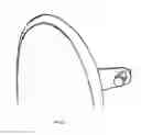
FIG. 1.—It shows a perspective of the golf shoe holder.
FIG. 1A.—It shows a horizontal front view of the golf shoe holder from the thinnest side.
FIG. 1B.—It shows a horizontal front view of the golf shoe holder from the widest side opposite the side shown in FIG. 1A.
FIG. 1C.—It shows a horizontal side view of the golf shoe holder.
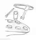
FIG. 2A.—It shows all of the pieces required for installing the golf shoe holder with dismountable cleats.
FIG. 2B.—It shows how the winding key (5) is inserted in the cleat (7) to dismount the cleat.
FIG. 2C.—It shows how the golf shoe holder with dismountable cleats is installed (1) in the large hole (2) between the shoe sole (6) and the cleat (7).
FIG. 2D.—It shows how the cleat is tightened with the winding key (5).
FIG. 2E.—It shows how the golf shoe holder with dismountable cleats (1) is fixed to the shoe sole (6).
FIG. 2F.—It shows how the tee (4) is inserted into the smaller hole (3) of the golf shoe holder with dismountable cleats (1).
FIG. 2G.—It shows how the tee (4) is totally introduced into the golf shoe holder with dismountable cleats (1) and this shall prevent the supporting foot from moving when attempting to hit the golf ball with the golf club.
| REFERENCE LIST |
| Number | Corresponds to: |
| 1 | Shoe holder with dismountable cleats |
| 2 | Large diameter hole |
| 3 | Small diameter hole |
| 4 | Tee |
| 5 | Winding key |
| 6 | Shoe sole |
| 7 | Cleats |
When looking at these figures, it may be observed how the golf shoe holder (1) with dismountable cleats (7) is structured, based on a single body part, elongated and thin, in a truncated cone (trapezoidal) form, elongated at the ends and rounded at said ends, with two holes: one with a large diameter (2) and one with a smaller diameter (3). The large diameter hole (2) is located at the widest end of the elongated part and the other hole, with a smaller diameter (3) is located far from the large hole (2) and close to the narrowest end of the part (1). They are used as follows: the large diameter (2) of the part (1) is to be placed within the cleats (7) and the shoe sole (6), by means of the threads (not shown) that both parts have and the smaller diameter hole (3) is where it is fastened to the grass by means of a tee (4).
Thus, the invention is focused on the fact that the supporting foot of a golfer does not move at the time of attempting to hit the golf ball with the golf clubs, as the golf shoe holder shall prevent this from happening.
To install the holder, firstly, the cleat (7) of the shoe is dismounted from the shoe sole (6) with the winding key (5) as shown in FIG. 2B. Then, the holder (1) is placed on the shoe sole (6) and the cleat (7) is put in place again, as shown in FIG. 2C and it is tightened with the winding key (5) as shown in FIG. 2D. Thus, it is placed and held to the shoe sole (6) as shown in FIG. 2E. FIG. 2F shows how the tee (4) is placed through the smaller hole (3) of the shoe holder (1) and, lastly, FIG. 2G shows how the tee (4) is dug into the ground, thus preventing the movement of the golf shoe.
Claims
1-5. (canceled)
6. A shoe affixer comprising:
a flat body having a first end and a second end;
a first hole in the body about the first end adapted to be installed between a cleat and a shoe sole; and
a second hole in the body about the second end adapted to hold a golf tee.
7. The shoe affixer of claim 6, wherein the affixer has an oblong shape, a trapezoidal, a rectangular, oval, ellipse, triangular, diamond, rhombus or parallelogram form.
8. The shoe affixer of claim 6, wherein the first end and the second end are rounded.
9. The shoe affixer of claim 6, wherein the affixer is adapted for being installed on either a right shoe or a left shoe.
10. The shoe affixer of claim 6, wherein the affixer is adapted for being installed on at least two cleats of a shoe.
11. The shoe affixer of claim 6, wherein the affixer is adapted for being installed on the cleat on a left side of a right shoe, a right side of a left shoe, a right side of a right shoe, or a left side of a left shoe.
12. The shoe affixer of claim 6, wherein the affixer is adapted for being installed on the cleat below the toe box of the shoe.
13. The shoe affixer of claim 6, wherein a portion of the affixer that is exposed after being secured to a shoe is decorated with decals, designs, advertising legends, instructions, or labels.
14. The shoe affixer of claim 6, wherein the affixer is made of materials that are resistant to the minimum traction required for their use.
15. A method of affixing a shoe to the ground comprising:
obtaining a shoe affixer comprising:
a flat body having a first end and a second end;
a first hole in the body about the first end adapted to be installed between a cleat and a shoe sole; and
a second hole in the body about the second end adapted to hold a golf tee;
securing the golf shoe affixer to the golf shoe by positioning the first hole of the shoe affixer between the cleats and the shoe sole; and
securing the shoe affixer to the ground by pinning a golf tee through the second hole of the affixer into the ground.
16. The method of claim 15, wherein the shoe affixer has an oblong shape, a trapezoidal, a rectangular, oval, ellipse, triangular, diamond, rhombus or parallelogram form.
17. The method of claim 15, wherein the first end and the second end of the shoe affixer are rounded.
18. The method of claim 15, wherein the shoe affixer is adapted for being secured on either a right shoe or a left shoe.
19. The method of claim 15, wherein the shoe affixer is adapted for being installed on at least two cleats of a shoe.
20. The method of claim 15, wherein the shoe affixer is adapted for being installed on the cleat on a left side of a right shoe, a right side of a left shoe, a right side of a right shoe, or a left side of a left shoe.
21. The method of claim 15, wherein the shoe affixer is adapted for being installed on the cleat below the toe box of the shoe.
22. The method of claim 15, wherein a portion of the shoe affixer that is exposed after being secured to a shoe is decorated with decals, designs, advertising legends, instructions, or labels.
23. The method of claim 15, wherein positioning the first hole of the shoe affixer between the cleats and the shoe sole further comprises dismounting the cleat from the shoe sole, placing the shoe affixer onto the shoe sole, remounting the cleat to the shoe sole over the first hole of the shoe affixer.
24. The method of claim 23, wherein the cleat is dismounted and remounted to the shoe sole with a winding key.
Images & Drawings included:

Sources:
- United States Patent and Trademark Office - verify current appl. status at the USPTO↗
Recent applications in this class:
- » 20230241475 2023-08-03
SWING PATH TRAINING APPARATUS - » 20220339515 2022-10-27
GOLF SWING TRAINING APPARATUS - » 20210197053 2021-07-01
Swing training assembly for swing sports including golf, baseball, tennis or hockey - » 20210197052 2021-07-01
Swing training assembly for swing sports including golf, baseball, tennis or hockey - » 20210197051 2021-07-01
Swing training assembly for swing sports including golf, baseball, tennis or hockey - » 20200384330 2020-12-10
Head alignment golf training aid - » 20200222779 2020-07-16
Swing training assembly for swing sports including golf, baseball, tennis or hockey - » 20190001208 2019-01-03
GOLF TRAINING AID - » 20170007899 2017-01-12
Golf swing training device - » 20160375335 2016-12-29
Golf putting training aid