Stemmed drinking receptacle holder
US20150305534A1
2015-10-29
14/632,934
2015-02-26
✅ Patent granted
US 9,788,673 B2
2017-10-17
-
-
Ingrid M Weinhold
David A. Gottardo, Attorney at Law
2035-02-26
Abstract:
This invention relates generally to a stemmed drinking receptacle holder, and more particularly to a holder utilizing a bore and channel configuration to prevent the receptacle from being dislodged therefrom. In one embodiment, the holder comprises a bracket defining a through bore configured to encircle a stem of the stemmed drinking receptacle, a channel defined in the bracket and connecting the through bore with an outer edge of the bracket, and a clamp adjustably connected to the bracket.
Applicant:
Interested in similar patents?
Get notified when new applications in this technology area are published.
Classification:
F16M13/022 » CPC further
Other supports for positioning apparatus or articles ; Means for steadying hand-held apparatus or articles for supporting on, or attaching to, an object, e.g. tree, gate, window-frame, cycle repositionable
F16M13/02 IPC
Other supports for positioning apparatus or articles ; Means for steadying hand-held apparatus or articles for supporting on, or attaching to, an object, e.g. tree, gate, window-frame, cycle
A47G23/0225 » CPC main
Other table equipment; Glass or bottle holders for drinking-glasses, plastic cups, or the like for one glass or cup attachable to a plate, table, or the like
A47G23/02 IPC
Other table equipment Glass or bottle holders
F16B2/10 » CPC further
Friction-grip releasable fastenings; Clamps, i.e. with gripping action effected by positive means other than the inherent resistance to deformation of the material of the fastening external, i.e. with contracting action using pivoting jaws
Description
CROSS REFERENCE TO RELATED APPLICATIONS
This application claims priority to U.S. Provisional Application Ser. No. 61/945,531 filed on Feb. 27, 2014.
TECHNICAL FIELD OF THE INVENTION
This invention relates generally to a stemmed drinking receptacle holder, and more particularly to a holder utilizing a bore and channel configuration to prevent the receptacle from being dislodged therefrom.
BACKGROUND OF THE INVENTION
At times, such as during picnics or other outings where table top surfaces may be unavailable, setting down a wine glass or other stemmed drinking receptacle may be difficult due to a risk of spilling the receptacle's contents. For example, if sitting in a lawn chair at an outdoor concert, one would typically have to constantly hold the wine glass in one's hand because no adequate table surface or other flat surface is available on which to place the glass.
While prior art drinking receptacle holders exist, such prior art holders are fraught with disadvantages. For example, numerous prior art drinking receptacle holders support the drinking receptacle at its base. However, because stemmed drinking receptacles tend to be “top heavy,” such base-supporting holders are ill-suited for supporting a stemmed drinking receptacle without a risk or tipping. While base-supporting drinking receptacles may also include one or more supports for supporting the bowl of a stemmed drinking receptacle, such holders tend to be cumbersome to use and transport.
Thus, what is needed is a stemmed drinking receptacle holder that supports the drinking receptacle at its bowl. The holder should secure the receptacle therein to prevent it from being dislodged from the holder, and be removably securable to other objects. The holder should also be easy to use and transport. The present invention solves the forgoing problems and provides other advantages as well.
SUMMARY OF THE INVENTION
This invention relates generally to a stemmed drinking receptacle holder, and more particularly to a holder utilizing a bore and channel configuration to prevent the receptacle from being dislodged therefrom. In one embodiment, the holder comprises a bracket defining a through bore configured to encircle a stem of the stemmed drinking receptacle, a channel defined in the bracket and connecting the through bore with an outer edge of the bracket, and a clamp adjustably connected to the bracket. The channel preferably defines a bore opening where the channel meets the bore and an edge opening where the channel meets the outer edge, with the bore opening preferably oriented about perpendicular to the edge opening. The bracket preferably defines at least side outer edges, with the edge opening defined in one of the side outer edges. The through bore defines a circumferal edge, with the bore opening preferably defined in a forward portion of the circumferal edge. In other embodiments, the bore of the bracket defines an angled inner wall configured to seat the bowl of the stemmed drinking receptacle.
The bracket preferably defines forward and rearward edges wherein the forward, rearward and side edges of the bracket define a rectangle, oval or other shape. The adjustable connection between the clamp and handle preferably comprises a frictional and rotational connection that facilitates a folding of the holder such that the bracket is positioned about adjacent to the clamp to optimize the holder's portability.
BRIEF DESCRIPTION OF THE DRAWINGS
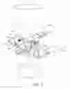
FIG. 1 illustrates one embodiment of the stemmed drinking receptacle holder holding a stemmed drinking receptacle;
FIG. 2 illustrates the stemmed drinking receptacle holder of FIG. 1;
FIG. 3 illustrates an alternate embodiment of the bracket of the stemmed drinking receptacle holder of FIGS. 1 and 2; and
FIG. 4 is a side elevation view of the stemmed drinking receptacle holder of FIGS. 1 and 2.
DESCRIPTION OF THE EMBODIMENTS
This invention relates generally to a stemmed drinking receptacle holder, and more particularly to a holder utilizing a bore and channel configuration to prevent the receptacle from being dislodged therefrom. In one embodiment of the invention, illustrated in FIGS. 1, 2 and 4, the stemmed drinking receptacle holder 5 comprises a bracket 10 defining a through bore 15 configured to encircle the stem 20 of a stemmed drinking receptacle 25 such that the bracket supports the drinking receptacle's bowl 30. The bracket 10, preferably elongated, preferably comprises a piece of rigid sheet-form material defining forward 35, rearward 40 and side outer edges 45 and 50. Of course, it is understood that non-sheet-form material could be utilized as well.
In a preferred embodiment, the forward, rearward and side edges of the bracket define a rectangle having a length of between about 4.0 in. and about 7.0 in., preferably between about 5.0 in. and about 6.0 in., and optimally about 5.5 in.; and a width of between about 1.0 in. and about 2.0 in., preferably between about 1.25 in. and about 1.5 in., and optimally about 1.25 in. The bracket has a thickness of between about 0.125 in. and about 0.75 in., preferably between about 0.25 in. and about 0.5 in., and optimally about 0.25 in, or 0.5 in. In other embodiments, the forward, rearward and side edges of the bracket define an oval or other geometrical shape as well.
The rigid sheet-form material preferably comprises translucent or non-translucent polycarbonate (i.e., Lexan®), polymethyl methacrylate (i.e., Plexiglas®) or other thermoplast or plastic materials understood in the art as having rigid properties. FIGS. 1-4 thus illustrate a bracket 10 comprising translucent polycarbonate or polymethyl methacrylate. However, in other embodiments, the bracket 10 is comprised of steel, aluminum or other metals, or of wood. A channel 55, having a width exceeding that of the drinking receptacle's stern 20, connects the through bore 15 with a side outer edge (45 or 50) of the bracket 10, with the channel defining a bore opening 60 where the channel meets the bore and an edge opening 65 where the channel meets and is coterminous with the bracket's outer edge.
The channel 55 preferably defines a pair of arcuate inner edges 56 and 58. However, in other embodiments (not illustrated) of the channel 55, the inner edges 56 and 58 are straight. The channel 55 has a length of between about 0.5 in. and about 2.0 in., preferably between about 1.0 in. and about 1.5 in., and optimally about 1.25 in. In a preferred embodiment of the invention, the bore opening 60 defined by the channel has a chordal width that is less than the diameter of the through bore 15. A clamp 70 is adjustably connected to the bracket 10 such that the holder 5 is removably securable to other objects (i.e., object 103).
Referring again to FIG. 2, the bore opening 60 is preferably oriented about perpendicular to the edge opening 65. The edge opening 65 is preferably defined in one of the bracket's side outer edges 45 or 50 while the bore opening 60 is preferably defined in a forward portion 75 of a circumferal edge 80 defined by the through bore 15. However, it is understood that the bore opening could be defined in a rearward portion 85 of the through bore's circumferal edge 80. It is further understood that the edge opening 65 could be defined in the forward 35 or rearward 40 edge of the bracket 10, with the bore edge 60 defined in a side portion 90 of the through bore's circumferal edge 80 as well.
The foregoing configuration better prevents the receptacle from falling from the holder than in a configuration where the channel joins the bore at an opening that is parallel with the opening where the channel joins the edge (i.e., a straight channel connecting the side edge of the bore with the side edge of the holding portion). In the latter configuration, a sideways bump of the glass could more easily dislodge the glass from the holder than in the former configuration.
In other embodiments of the invention, as illustrated in FIG. 3, the through bore 15 of the bracket 10 defines a tapered or angled inner wall 95 such that the wall better conforms to an angle of the bowl 30 of the stemmed drinking receptacle 25 (FIG. 1). The angle of the bore's wall is between about 15 degrees and about 90 degrees from the horizontal, more preferably between about 30 degrees and about 60 degrees from the horizontal, and optimally about 45 degrees from the horizontal.
Referring again to FIGS. 1, 2 and also to FIG. 4, a common spring clamp 70 or spring-biased “squeeze” clamp is rotatably connected to the bracket 10, preferably connecting a handle 100 of the spring clamp to the bracket at a location rearward of the bore 15 and channel 55. The rotatable connection is frictionally adjustable to allow the bracket 10 to be frictionally and rotationally positioned 360 degrees in relation to the clamp 70 to facilitate a positioning of the bracket regardless of the location of the clamp when clamped to another object 103, (i.e., the arm-rest of a lawn chair). The rotatable connection also facilitates a “folding” of the holder such that the bracket is positioned about adjacent to the clamp's jaw to optimize the holder's portability.
A coaxial connector bore 105 (FIGS. 3 and 4) is thus defined in both the clamp 70 and bracket 10 such that a common screw 110 is inserted there-through and secured with a wing-nut 115. The wing-nut 115 is rotated onto the screw 110 to a desired tightness to create friction between the bracket 10 and clamp 70 to facilitate the frictional rotation between the two. While a screw and wing-nut is preferably utilized to frictionally and rotationally connect the bracket and clamp to one another, any other connecting means understood in the art (i.e., nut/bolt; or rivet, etc.) may be utilized as well. It is thus understood that the countersink 120 (FIGS. 3 and 4) defined within the bracket 10 at the top of bore 105 could have a different shape (i.e., other than angled to conform to the head of screw 110), or be eliminated altogether. Also, any other clamping means understood in the art (i.e., a C-clamp) may be utilized in place of the disclosed spring clamp as well. Furthermore, while a frictional and rotational connection is utilized between the clamp and bracket in the preferred embodiment of the invention, it is understood that the bracket and clamp may be fixably attached to one another as well.
While this foregoing description and accompanying drawings are illustrative of the present invention, other variations in structure and method are possible without departing from the invention's spirit and scope.
Claims
We claim:1. A holder for a stemmed drinking receptacle comprising:
a bracket defining a through bore configured to encircle a stern of the stemmed drinking receptacle;
a channel defined in the bracket and connecting the through bore with an outer edge of the bracket, the channel defining a bore opening where the channel meets the bore and an edge opening where the channel meets the outer edge, the bore opening oriented about perpendicular to the edge opening; and
a clamp adjustably connected to the bracket.
2. The holder of claim 1 wherein the bracket defines at least side outer edges, said edge opening defined in one of the side outer edges.
3. The holder of claim 2 wherein the through bore defines a circumferal edge, said bore opening defined in a forward portion of the circumferal edge.
4. The holder of claim 1 wherein the adjustable connection comprises a frictional and rotational connection.
5. The holder of claim 1 wherein the clamp comprises a spring clamp.
6. The holder of claim 5 wherein adjustable connection of the clamp to the bracket is located on a handle of the spring clamp and rearward of the bore and channel on the bracket.
7. The holder of claim 4 wherein the adjustable connection comprises a screw and wing nut.
8. The holder of claim 3 wherein the bracket also defines forward and rearward edges, the forward, rearward and side outer edges of the bracket defining a rectangle.
9. The holder of claim 8 wherein the rectangle defines a length of between about 4.0 in. and about 7.0 in and a width of between about 1.0 in. and about 2.0 in.
10. The holder of claim 8 wherein the rectangle defines a length of between about 5.0 in. and about 6.0 in and a width of between about 1.25 in. and about 1.5 in.
11. The holder of claim 8 wherein the rectangle defines a length of about 5.5 in and a width of between about 1.25 in.
12. The holder of claim 3 wherein the bracket has a thickness of between about 0.125 in. and about 0.75 in.
13. The holder of claim 3 wherein the bracket has a thickness of between about 0.25 in. and about 0.5 in.
14. The holder of claim 3 wherein the bracket has a thickness of about 0.25 in.
15. The holder of claim 3 wherein the bracket has a thickness of about 0.5 in.
16. The holder of claim 3 wherein the bore of the bracket defines an angled inner wall.
17. The holder of claim 16 wherein the angled inner wall is between about 15 degrees and about 90 degrees from the horizontal.
18. The holder of claim 16 wherein the angled inner wall is between about 30 degrees and about 60 degrees from the horizontal.
19. The holder of claim 16 wherein the angled inner wall is about 45 degree from the horizontal.
20. The holder of claim 3 wherein the adjustable connection between the clamp and bracket facilitates a folding of the holder such that the bracket is positioned about adjacent to the clamp to optimize the holder's portability.
Images & Drawings included:


Sources:
- United States Patent and Trademark Office - verify current appl. status at the USPTO↗
Recent applications in this class:
- » 20250268407 2025-08-28
MAGNETIC CONNECTION APPARATUS - » 20250248551 2025-08-07
BEVERAGE CADDY - » 20250120528 2025-04-17
HEAVY DUTY DETACHABLE BEVERAGE AND PHONE HOLDER AND ASSOCIATED SYSTEMS AND METHODS - » 20250009156 2025-01-09
Separable Object Holder - » 20240260774 2024-08-08
BEVERAGE CADDY - » 20240245244 2024-07-25
Self-Righting Hydration Cup Holder - » 20240008667 2024-01-11
Magnetic connection apparatus - » 20240000255 2024-01-04
Mounting Apparatus for Portable Devices - » 20230180953 2023-06-15
Cup holder mount for exercise machine - » 20230157468 2023-05-25
CUP HOLDER