Deburring brush
US20150306740A1
2015-10-29
14/675,869
2015-04-01
✅ Patent granted
US 9,839,992 B2
2017-12-12
-
-
Joseph J Hail | Joel Crandall
AKC Patents, LLC | Aliki K. Collins
2035-04-01
Abstract:
The present invention discloses a deburring brush, comprising a pressing plate, jacking posts, copper sleeves, gaskets, guide posts, springs and bristle units. When the bristle units need replacement, it only needs to place the deburring brush on the ground and then press down edges of the front side of a top plate, so that all the bristle units will fall off against the suction force of strong magnets under the action of each jacking post. According to the present invention, it avoids being time consuming and labor intensive due to removing the bristle units one by one by using a screw driver or other similar devices while replacing the bristle units, and at the same time the replacing speed of bristles is greatly increased.
Inventors:
- Yongning WANG 30 🇨🇳 Qinhuangdao, China
- Zhihua ZHU 63 🇨🇳 Qinhuangdao, China
- Changhai LI 55 🇨🇳 Qinhuangdao, China
- Bowen XUE 111 🇨🇳 Qinhuangdao, China
- Jiandong GUO 131 🇨🇳 Qinhuangdao, China
- Jiandong Guo 1 🇨🇳 Qinhuangadao, China
- Yongning Wang 1 🇨🇳 Qinhuangado, China
Assignee:
- KSM CASTINGS QINHUANGDAO CO., LTD. 1 🇨🇳 Qinhuangdao, China
- KSM CASTINGS QINHUANGDAO Co., LTD. 1 🇨🇳 Qinhuangdao, Hebei Province, China
Applicant:
Interested in similar patents?
Get notified when new applications in this technology area are published.
Classification:
A46B5/0095 » CPC further
Brush bodies; Handles integral with brushware Removable or interchangeable brush heads
A46B9/026 » CPC further
Arrangements of the bristles in the brush body; Position or arrangement of bristles in relation to surface of the brush body, e.g. inclined, in rows, in groups where the surface of the brush body or carrier is not in one plane, e.g. not flat
A46B2200/3086 » CPC further
Brushes characterized by their functions, uses or applications; Brushes for cleaning or polishing Brushes for polishing
A46B2200/3093 » CPC further
Brushes characterized by their functions, uses or applications; Brushes for cleaning or polishing Brush with abrasive properties, e.g. wire bristles
B24D13/10 » CPC main
Wheels having flexibly-acting working parts, e.g. buffing wheels; Mountings therefor acting by their periphery comprising assemblies of brushes
A46B5/00 IPC
Brush bodies; Handles integral with brushware
B24B9/04 » CPC further
Machines or devices designed for grinding edges or bevels on work or for removing burrs; Accessories therefor characterised by a special design with respect to properties of materials specific to articles to be ground of metal, e.g. skate blades
A46B7/04 » CPC further
Bristle carriers arranged in the brush body interchangeably removable bristle carriers
A46B9/02 IPC
Arrangements of the bristles in the brush body Position or arrangement of bristles in relation to surface of the brush body, e.g. inclined, in rows, in groups
Description
TECHNICAL FIELD
The present invention relates to a surface treatment device, more particularly to a metal surface treatment device.
BACKGROUND ART
During manufacturing process of aluminum alloy wheels, deburring cost accounts for a very large part of the overall cost due to huge consumption of deburring brushes. More and more enterprises have begun exploring and developing a variety of novel deburring brushes to reduce the deburring cost. A deburring brush with replaceable bristles is a future development trend of wheel deburring brushes due to its flexibility, its chassis part being reusable, thus greatly reducing the cost. However, how to make it convenient to disassemble the shortened bristles while reducing the cost is a new technical problem we are faced with.
Invention Contents:
An object of the present invention is providing a wheel deburring brush with conveniently replaceable bristles.
To achieve the above object, the present invention adopts the following technical solution: a deburring brush comprises a pressing plate, jacking posts, copper sleeves, gaskets, guide posts, springs, a bottom plate, magnets, a top plate and bristle units. The magnet is fixed between the bottom plate and the top plate, and the magnets grip the bristle units, thus forming a body of the deburring brush.
The guide posts are fixed below the bottom plate, and the copper sleeves cooperating with the guide posts are embedded on the pressing plate; the pressing plate, above which are mounted the jacking posts, is fixed between the springs and the gaskets at the ends of the guide posts; and the top ends of the jacking posts pass through holes of the bottom plate and the magnets, and are in contact with the bottoms of the bristle units.
When the bristle units need replacement, it only needs to place the deburring brush on the ground and then press down edges of the front side of the top plate, so that all the bristle units will fall off against the suction force of the strong magnets under the action of each jacking post.
According to the present invention, it avoids being time consuming and labor intensive due to removing the bristle units one by one by using a screw driver or other similar devices while replacing the bristle units, and at the same time the replacing speed of bristles is greatly increased.
DESCRIPTION OF DRAWINGS
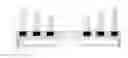
FIG. 1 is a front view of an improved displaceable wheel deburring brush according to the present invention.
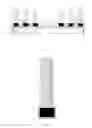
FIG. 2 is a front view of a bristle unit of an improved displaceable wheel deburring brush according to the present invention.
In the figures, 1—pressing plate, 2—jacking post, 3—copper sleeve, 4—gasket, 5—guide post, 6—spring, 7—bottom plate, 8—magnet, 9—top plate, 10—bristle unit.
DETAILED DESCRIPTION
Details and operation of the specific device provided by the present invention will be described below in conjunction with the accompanying drawings.
The deburring brush comprises a pressing plate 1, jacking posts 2, copper sleeves 3, gaskets 4, guide posts 5, springs 6, a bottom plate 7, magnets 8, a top plate 9 and bristle units 10. The magnets 8 are fixed between the bottom plate 7 and the top plate 9, and the magnets 8 grip the bristle units 10, thus forming a body of the deburring brush.
The guide posts 5 are fixed below the bottom plate 7, and the copper sleeves 3 cooperating with the guide posts 5 are embedded on the pressing plate 1; the pressing plate 1, above which are mounted the jacking posts 2, is fixed between the springs 6 and the gaskets 4 at the ends of the guide posts 5; and the top ends of the jacking posts 2 pass through holes of the bottom plate 7 and the magnets 8, and are in contact with the bottoms of the bristle units 10.
During operation, when the bristle units 10 need replacement, it only needs to place the deburring brush on the ground and then press down edges of the front side of the top plate 9, so that all the bristle units 10 will fall off against the suction force of the magnets 8 under the action of each jacking post 2.
Claims
1. A deburring brush, comprising a pressing plate (1), jacking posts (2), copper sleeves (3), gaskets (4), guide posts (5), springs (6), a bottom plate (7), magnets (8), a top plate (9) and bristle units (10), characterized in that the magnets (8) are fixed between the bottom plate (7) and the top plate (9), and the magnets (8) grip the bristle units (10), thus forming a body of the deburring brush; the guide posts (5) are fixed below the bottom plate (7), and the copper sleeves (3) cooperating with the guide posts (5) are embedded on the pressing plate (1); the pressing plate (1), above which are mounted the jacking posts (2), is fixed between the springs (6) and the gaskets (4) at the ends of the guide posts (5); and the top ends of the jacking posts (2) pass through holes of the bottom plate (7) and the magnets (8), and are in contact with the bottoms of the bristle units (10).
Images & Drawings included:
Sources:
- United States Patent and Trademark Office - verify current appl. status at the USPTO↗
Similar patent applications:
- » 20130225048
Brush-type deburring machine - » 20130260652
Brush-type deburring machine - » 20140242892
Rotary abrasive brush for deburring and method of manufacturing - » 20160001419
Brush-type deburring machine for multiple cutting with individual deburring
Recent applications in this class:
- » 20240238940 2024-07-18
DEBURRING MECHANISM AND DEBURRING ASSEMBLY - » 20200198097 2020-06-25
Rotary brush - » 20200139514 2020-05-07
Double-stringer rotary brush - » 20190047122 2019-02-14
Roll shaft for brush roll and brush roll - » 20170304997 2017-10-26
Polishing brush - » 20160016293 2016-01-21
LINEAR GRINDING MEMBER, BRUSH-LIKE GRINDING STONE, AND METHOD FOR MANUFACTURING LINEAR GRINDING MEMBER - » 20140106651 2014-04-17
Grinding Head - » 20120100333 2012-04-26
RUBBING CLOTH FOR RUBBING PROCESS OF ALIGNMENT FILM - » 20120071071 2012-03-22
Abrasive impregnated brush - » 20120071069 2012-03-22
Surface treatment device