COMBINATION FIN AND HEAT PIPE ASSEMBLY
US20150308749A1
2015-10-29
14/446,101
2014-07-29
Abstract:
A combination fin and heat pipe assembly includes a heat pipe, and a plurality of radiation fins each including a fin plate, a mounting through hole in the fin plate that receives the heat pipe, an annular flange extending from one side of the fin plate around the mounting through hole and two opposing arched slots each cut through a part of the fin plate adjacent to a peripheral wall of the annular flange to partially separate the annular flange from the respective fin plate. The annular flange has the peripheral wall deformed on two opposite sides corresponding to the arched slots and forced into tight engagement with the periphery of the heat pipe.
Interested in similar patents?
Get notified when new applications in this technology area are published.
Classification:
F28D15/02 » CPC main
Heat-exchange apparatus with the intermediate heat-transfer medium in closed tubes passing into or through the conduit walls ; Heat-exchange apparatus employing intermediate heat-transfer medium or bodies in which the medium condenses and evaporates, e.g. heat pipes
Description
BACKGROUND OF THE INVENTION
(a) Field of the Invention
The present invention relates to heat sink technology, and more particularly to a combination fin and heat pipe assembly, which comprises a heat pipe and a plurality of radiation fins press-fitted onto the heat pipe.
(b) Description of the Prior Art
In conventional heat sink designs, radiation fins and heat pipes are commonly bonded together by welding. However, welding operation is not in line with environmental protection, and its process is cumbersome and can produce a thermal resistance phenomenon. An improvement in this regard is necessary.
Taiwan Patent No. 1270339 discloses a method for forming heat-dissipating fins by squeeze-shaping: providing a plurality of heat-dissipating fins and at least one heat conduit; forming at least a circular protrusive wall with through holes on the surface of each heat-dissipating fins or forming through holes with circular protrusive walls of axial/radial dissected slot as well as buckling pieces disposed at two lateral sides; arranging the plurality of heat-dissipating fins by way of the buckling pieces to form a spaced-and-aligned fin set; disposing the heat conduit inside through holes of the heat-dissipating fins; carrying out the squeeze-shaping process, that is, by way of a processing tool with a plurality of molding pieces and a pressure-imposing technique, imposing a strong pressure on the surface of the circular protrusive wall of the heat-dissipating fins so as to generate deformation and squeeze, making the heat-dissipating fins and the heat conduit into an integrated object; and completing the fabrication of the heat-dissipating device. However, because this design simply generates deformation on one side, it cannot achieve a high level of connection tightness in a balanced manner.
In the above-mentioned prior art process of imposing a strong pressure on the surface of the circular protrusive wall of the heat-dissipating fins so as to generate deformation and squeeze, making the heat-dissipating fins and the heat conduit into an integrated object, it is difficult to control the amount of deformation of the circular protrusive walls of the heat-dissipating fins and the at least one heat conduit. The at least one heat conduit can be excessively compressed, causing damage or destruction of the internal capillary structure of the at least one heat conduit. If the amount of deformation of the circular protrusive walls of the heat-dissipating fins is smaller than the amount of deformation of the at least one heat conduit, the circular protrusive walls of the heat-dissipating fins will not be fully kept in contact with the at least one heat conduit, and a clearance will be generated between the circular protrusive walls of the heat-dissipating fins and the at least one heat conduit. Thus, it cannot achieve a tight connection effect.
SUMMARY OF THE INVENTION
The present invention has been accomplished under the circumstances in view. It is therefore the main object of the present invention to provide a combination fin and heat pipe assembly, which comprises a plurality of radiation fins and a heat pipe. Each radiation fin comprises a fin plate, a mounting through hole in the fin plate, an annular flange extending from one side of the fin plate around the mounting through hole, and two opposing arched slots each cut through a part of the fin plate immediately adjacent to a peripheral wall of the annular flange to partially separate the annular flange from the respective fin plate. The heat pipe is inserted through the mounting through hole of each radiation fin, and then the peripheral wall of the annular flange of each radiation fin and the heat pipe are partially deformed and forced into tight engagement with each other.
Preferably, the peripheral wall of the annular flange of each radiation fin around the mounting through hole and the periphery of the heat pipe are deformed on two opposite sides, keeping the peripheral wall of the annular flange of each radiation fin and the periphery of the heat pipe in tight engagement with each other on two opposite sides in a balanced manner.
In one embodiment of the present invention, the peripheral wall of the annular flange of each radiation fin around the mounting through hole and the periphery of the heat pipe are flattened on two opposite sides, keeping the peripheral wall of the annular flange of each radiation fin and the periphery of the heat pipe in tight engagement with each other, achieving a tight fit effect of engagement on two opposite sides in a balanced manner.
In another embodiment of the present invention, the peripheral wall of the annular flange of each radiation fin around the mounting through hole and the periphery of the heat pipe are deformed and inwardly curved on two opposite sides, keeping the peripheral wall of the annular flange of each radiation fin and the periphery of the heat pipe in tight engagement with each other, achieving a tight fit effect of engagement on two opposite sides in a balanced manner.
BRIEF DESCRIPTION OF THE DRAWINGS
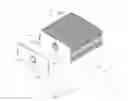
FIG. 1 is an exploded view of a combination fin and heat pipe assembly in accordance with a first embodiment of the present invention.
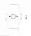
FIG. 2 is a perspective assembly view of the combination fin and heat pipe assembly in accordance with the first embodiment of the present invention before deformation of the peripheral walls of the annular flanges of the radiation fins.
FIG. 3 is a front sectional view of the present invention, illustrating the heat pipe inserted through the mounting through holes of the radiation fins before deformation of the peripheral walls of the annular flanges of the radiation fins.
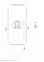
FIG. 4 corresponds to FIG. 2, illustrating two opposite sides of the peripheral wall of the annular flange of each radiation fin having been flattened.
FIG. 5 corresponds to FIG. 3, illustrating two opposite sides of the peripheral wall of the annular flange of each radiation fin having been flattened.
FIG. 6 is similar to FIG. 4, illustrating two opposite sides of the peripheral wall of the annular flange of each radiation fin having been deformed and inwardly curved.
FIG. 7 is a sectional view of FIG. 6.
FIG. 8 is a sectional view of another alternate form of the present invention, illustrating radiation fins mounted on a flat oval heat pipe.
FIG. 9 corresponds to FIG. 8, illustrating two opposite sides of the peripheral wall of the annular flange of each radiation fin having been deformed and inwardly curved.
DETAILED DESCRIPTION OF THE PREFERRED EMBODIMENTS
Referring to FIGS. 1-5, a combination fin and heat pipe assembly in accordance with the present invention is shown. As illustrated, the combination fin and heat pipe assembly comprises a plurality of radiation fins 1 and a heat pipe 2.
The radiation fins 1 are arranged in parallel, each comprising a fin plate 10, a mounting through hole 11 in the fin plate 10, an annular flange 111 extending from one side of the fin plate 10 around the mounting through hole 11, and two opposing arched slots 12 each cut through a part of the fin plate 10 immediately adjacent to a peripheral wall 111a of the annular flange 111 to partially separate the annular flange 111 from the respective fin plate 10.
The heat pipe 2 is inserted through the mounting through hole 11 of each of the radiation fins 1.
After insertion of the heat pipe 2 through the mounting through holes 11 of the radiation fins 1 (see FIG. 2 and FIG. 3), a stamping technique is employed to deform two opposite sides of the peripheral wall 111a of the annular flange 111 (see FIG. 4 and FIG. 5), forcing two opposite sides of the peripheral wall 111a of the annular flange 111 corresponding to the two arched slots 12 of the radiation fin 1 into tight friction engagement with the periphery of the heat pipe 2. Because the arched slots 12 partially separate the annular flange 111 from the respective fin plate 10, the arched slots 12 allow the two opposite sides of the peripheral wall 111a to be easily deformed.
According to the present invention, two opposite sides of the peripheral wall 111a of the annular flange 111 of each radiation fin 1 are symmetrically and equally deformed and forced into friction engagement with the periphery of the heat pipe 2, assuring a high level of connection tightness between the peripheral wall 111a and the heat pipe 2 without excessively compressing the pipe body of the heat pipe 2 or causing any clearance between the peripheral wall 111a and the heat pipe 2.
In the aforesaid embodiment, two opposite sides of the peripheral wall 111a of the annular flange 111 of the radiation fin 1 around the mounting through hole 11 are symmetrically and equally flattened, achieving a tight fit effect of engagement on two opposite sides in a balanced manner.
In the aforesaid embodiment, two opposite sides of the peripheral wall 111a of the annular flange 111 of each radiation fin 1 around the mounting through hole 11 are flattened and forced into tight engagement with the periphery of the heat pipe 2. However, the invention is not limited to this design. In an alternate form of the present invention, as shown in FIG. 6 and FIG. 7, the peripheral wall 111a of the annular flange 111 of each radiation fin 1 around the mounting through hole 11 and the periphery of the heat pipe 2 are deformed and inwardly curved on two opposite sides, keeping the peripheral wall 111a of the annular flange 111 of each radiation fin 1 and the periphery of the heat pipe 2 in tight engagement with each other on two opposite sides in a balanced manner.
Conventional heat pipes have different sizes and different shapes. The invention is applicable to round heat pipes as well as flat oval heat pipes. As illustrated in FIG. 8, two opposite sides of the peripheral wall 111a of the annular flange 111 of the radiation fin 1 around the mounting through hole 11 are symmetrically and equally flattened and forced into tight engagement with two opposite flat surfaces of the flat oval heat pipe 2 on two opposite sides in a balanced manner.
In still another alternate form of the present invention, as shown in FIG. 9, the peripheral wall 111a of the annular flange 111 of each radiation fin 1 around the mounting through hole 11 and the periphery of the flat oval heat pipe 2 are deformed and inwardly curved on two opposite sides, keeping the peripheral wall 111a of the annular flange 111 of each radiation fin 1 and the periphery of the heat pipe 2 in tight engagement with each other on two opposite sides in a balanced manner.
The technical feature of the combination fin and heat pipe assembly of the present invention is unique and quite different from conventional designs. By stamping a part of each radiation fin and the heat pipe on two opposite sides, the peripheral wall of each radiation fin around the mounting through hole and the heat pipe are equally deformed in a balanced manner, assuring a high level of connection tightness and stability without excessively deforming the heat pipe.
Although particular embodiments of the invention have been described in detail for purposes of illustration, various modifications and enhancements may be made without departing from the spirit and scope of the invention. Accordingly, the invention is not to be limited except as by the appended claims.
Claims
What is claimed is:1. A combination fin and heat pipe assembly, comprising:
a heat pipe; and
a plurality of radiation fins mounted on said heat pipe arranged in parallel, each said radiation fin comprising a fin plate, a mounting through hole in said fin plate for receiving said heat pipe, an annular flange extending from one side of said fin plate around said mounting through hole, and two opposing arched slots each cut through a part of said fin plate immediately adjacent to a peripheral wall of said annular flange to partially separate said annular flange from said fin plate, wherein the peripheral wall of said annular flange is partially deformed and forced into tight engagement with the periphery of said heat pipe.
2. The combination fin and heat pipe assembly as claimed in claim 1, wherein the peripheral wall of said annular flange of each said radiation fin around said mounting through hole and the periphery of said heat pipe are symmetrically and equally deformed on two opposite sides and forced into tight engagement with each other.
3. The combination fin and heat pipe assembly as claimed in claim 1, wherein the peripheral wall of said annular flange of each said radiation fin around said mounting through hole and the periphery of said heat pipe are flattened on two opposite sides and forced into tight engagement with each other.
4. The combination fin and heat pipe assembly as claimed in claim 1, wherein the peripheral wall of said annular flange of each said radiation fin around said mounting through hole and the periphery of said heat pipe are inwardly curved on two opposite sides and forced into tight engagement with each other.
5. The combination fin and heat pipe assembly as claimed in claim 1, wherein said heat pipe is a round pipe.
6. The combination fin and heat pipe assembly as claimed in claim 1, wherein said heat pipe is a flat oval pipe.
Images & Drawings included:


Sources:
- United States Patent and Trademark Office - verify current appl. status at the USPTO↗
Similar patent applications:
Recent applications in this class:
- » 20250164193 2025-05-22
HEAT TRANSFER APPARATUS AND METHOD - » 20250123058 2025-04-17
MULTILAYER HIGH ASPECT RATIO MICROCHANNEL DEVICE - » 20240344772 2024-10-17
HEAT SINK APPARATUS - » 20240125558 2024-04-18
HEAT EXCHANGER - » 20240077259 2024-03-07
HEAT PIPES AND VAPOR CHAMBERS MANUFACTURED USING A VACUUM PROCESS - » 20230106794 2023-04-06
Heat sink - » 20220260319 2022-08-18
THERMOELECTRIC POWER GENERATION SYSTEM - » 20220214115 2022-07-07
Vapor chamber - » 20210318072 2021-10-14
Cooling device with superimposed fin groups - » 20210285728 2021-09-16
Immersion cooling system