Jewelry clasp
US20150337880A1
2015-11-26
14/568,352
2014-12-12
✅ Patent granted
US 9,599,133 B2
2017-03-21
-
-
Jack W Lavinder
2034-12-12
Abstract:
A jewelry clasp comprises a male member having prong. A distal groove of the prong is configured to glide into a bore slot of a female member. A barrier wall within the bore slot is configured to stop the prong. One or more safety pegs are configured to retract a spring held in place by a housing beam peg and support beam peg as the prong glides into the bore slot.
Inventors:
- Cheryl Yvonne Gordon 1 🇺🇸 Long Beach, CA, United States
- Edgar Jamkochian 1 🇺🇸 Los Angeles, CA, United States
Assignee:
- Mediclasp, LLC 1 🇺🇸 Long Beach, CA, United States
Applicant:
Interested in similar patents?
Get notified when new applications in this technology area are published.
Classification:
F16B2/02 » CPC main
Friction-grip releasable fastenings Clamps, i.e. with gripping action effected by positive means other than the inherent resistance to deformation of the material of the fastening
A44C5/2085 » CPC further
Bracelets; Wrist-watch straps; Fastenings for bracelets or wrist-watch straps; Fasteners for straps, chains or the like for open straps, chains or the like with the two ends sliding transversally to the main plane of the strap or chain
A44C5/20 IPC
Bracelets; Wrist-watch straps; Fastenings for bracelets or wrist-watch straps; Fasteners for straps, chains or the like for open straps, chains or the like
Y10T24/45257 » CPC further
Buckles, buttons, clasps, etc.; Separable-fastener or required component thereof [e.g., projection and cavity to complete interlock] including member having distinct formations and mating member selectively interlocking therewith; Resilient element [e.g., with spring] Snap with cavity
Description
RELATED APPLICATION INFORMATION
This Application claims priority from U.S. Provisional Application Ser. No. 61/963,690, entitled “Medi-Clasp”, and filed on Dec. 12, 2013.
FIELD OF THE INVENTION
This invention generally relates to a jewelry clasp. More specifically, the present invention relates to a jewelry clasp having a male member prong with an attached facing wall with a distal groove of the prong that glides into the female member bore slot with a barrier wall to stop the prong.
SUMMARY OF THE INVENTION
In order to solve the problems and shortcomings of the prior art, according to one preferred embodiment, a jewelry clasp, comprises: a male member having prong; distal groove of the prong configured to glide into a bore slot of a female member a barrier wall within the bore slot configured to stop the prong; and one or more safety pegs configured to retracted a spring held in place by a housing beam peg and support beam peg as the prong glides into the bore slot.
BRIEF DESCRIPTION OF THE DRAWINGS
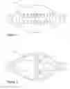
FIG. 1 is a top elevational view of the jewelry clasp according to one embodiment;
FIG. 2 is a bottom elevational view of the jewelry clasp according to the embodiment of FIG. 1; and
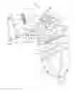
FIG. 3 is a diagrammatic bottom-left perspective exploded view of the jewelry clasp according to the embodiments of FIGS. 1 and 2.
DETAILED DESCRIPTION OF THE PREFERRED EMBODIMENTS
For the purpose of illustrating the invention, there is shown in the accompanying drawings several embodiments of the invention. However, it should be understood by those of ordinary skill in the art that the invention is not limited to the precise arrangements and instrumentalities shown therein and described below.
The jewelry clasp is disclosed in accordance with preferred embodiments of the present invention and is illustrated in FIGS. 1-3 wherein like reference numerals are used throughout to designate like elements.
With reference to FIG. 1, a top elevational view of a jewelry clasp 100 according to one embodiment is shown.
With reference to FIG. 2, a bottom elevational view of the jewelry clasp 100 according to the embodiment of FIG. 1 is shown.
With reference to FIG. 3, an exploded bottom-left perspective view of the jewelry clasp 100 according to one embodiment is shown. A male member (1) prong (2), having a base (7) and sidewalls (6), may be ¾ the length of its attached facing wall (24). A primary sliding groove (16) of the prong (2) may glide into a bore slot (4) of a female member (3), the female member (3) having a base (8), a support beam (12) and sidewalls (15). In one embodiment, the bore slot may be ¾ the length of its attached facing wall (25) with a barrier wall (26) to stop the prong (2). As the prong (2) glides along the tracking grooves (17A), (17B) and (17C) it may cause the housing beam (19) safety pegs (21A and 21B) to retract the spring (18) that may be held in place by housing beam peg (20) and the support beam peg (13). The cross beam (11) has two blinded adjacent openings that may be in an alignment with the housing beam safety pegs (21A and 21B).
In one embodiment, once the prong (2) is inserted into the bore slot (4) completely, spring (18) releases and the housing beam (19) rests between the crossbeam (11) alignment notches (10A and 10B) to maintain smooth traction and retraction of the spring (18). The spring cradle (14) escorts and prevents buckling of the spring (18). The cover plate (22) connecting holes (23A), (23B) and (23C) fits over the female member (3) stationary pegs (9A, 9B and 9C) to conceal the inner components. The housing beam (19) safety pegs (21A and 21B) lock into place with the tracking grooves (17B and 17C) on the prong (2). The two-part clasp male member (1) and female member (3) mechanism may be interlocked in place for a lateral engagement. While groove (16) may be the primary gliding groove, groove (17A) may be a secondary gliding groove to steer the prong through the bore and tracking grooves (17B and 17C) to lock into the safety pegs (21A and 21B).
The clasp 100 is thus configured for a chain or cord to be attached to the loops (5A and 5B) to create a necklace, bracelet or anklet
The various embodiments described above are provided by way of illustration only and should not be construed to limit the invention. Those skilled in the art will readily recognize various modifications and changes that may be made to the claimed invention without following the example embodiments and applications illustrated and described herein, and without departing from the true spirit and scope of the claimed invention, which is set forth in the following claims.
Claims
What is claimed is:1. A jewelry clasp, comprising:
a male member having prong;
distal groove of the prong configured to glide into a bore slot of a female member a barrier wall within the bore slot configured to stop the prong; and
one or more safety pegs configured to retracted a spring held in place by a housing beam peg and support beam peg as the prong glides into the bore slot.
2. The jewelry clasp of claim 1, further comprising a hosing beam that rests between crossbeam alignment notches to maintain smooth traction and retraction of the spring.
3. The jewelry clasp of claim 1, further comprising a cover plate that fits over the female member.
4. The jewelry clasp of claim 1 further comprising a housing beam comprising tracking grooves for the prong.
Images & Drawings included:

Sources:
- United States Patent and Trademark Office - verify current appl. status at the USPTO↗
Similar patent applications:
- » 20170354212
JEWELRY CLASP HAVING TWO FASTENING PARTS AND USE OF SAID JEWELRY CLASP, BRACELET, AND KIT - » 20060123845
Magnetic jewelry clasp and article of jewelry - » 20070240452
Magnetic jewelry clasp and article of jewelry - » 20080060172
Magnetic jewelry clasp that is attachable and detachable to existing jewelry by the user - » 13285950
Jewelry clasp - » 10779433
Magnetic jewelry clasp - » 15958060
Jewelry clasp - » 14271583
Jewelry clasp - » 10443486
Apparatus for fastening jewelry clasps - » 14186053
Jewelry clasp
Recent applications in this class:
- » 20250283492 2025-09-11
JOINT STRUCTURE - » 20250223983 2025-07-10
SYSTEM, METHOD, AND APPARATUS FOR CLAMPING - » 20250198434 2025-06-19
LATCH MECHANISM FOR A PROTECTIVE CASE - » 20250012304 2025-01-09
SYSTEM, METHOD, AND APPARATUS FOR CLAMPING - » 20240401620 2024-12-05
Quick Detach Shooting Stick - » 20240401619 2024-12-05
MAGNETIC CLIPS - » 20240392816 2024-11-28
JOINT STRUCTURE - » 20240125340 2024-04-18
LOCKING ASSEMBLY - » 20230383775 2023-11-30
Joint structure - » 20230383774 2023-11-30
System, method, and apparatus for clamping