Fuel tank mounted refueling device
US20150343896A1
2015-12-03
14/720,060
2015-05-22
✅ Patent granted
US 9,764,637 B2
2017-09-19
-
-
Andrew Perreault
Clifford H. Kraft
2035-06-30
Abstract:
A refueling device that when mounted to a marine fuel tank facilitates refueling and minimizes the propensity for both spit-back and well back while simultaneously allowing a free flowing open pathway through which vapors generated by the refueling event may pass unencumbered.
Inventors:
- Marvin Peplow 10 🇺🇸 Bartlett, IL, United States
- Christopher Brown 10 🇺🇸 Merritt Island, FL, United States
Assignee:
- Bluskies International LLC 4 🇺🇸 Bartlett, IL, United States
- BlueSkies International, LLC 1 🇺🇸 Nashville, TN, United States
Applicant:
Interested in similar patents?
Get notified when new applications in this technology area are published.
Classification:
B60K15/0406 » CPC main
Arrangement in connection with fuel supply of combustion engines or other fuel consuming energy converters, e.g. fuel cells ; Mounting or construction of fuel tanks; Fuel tanks; Tank inlets Filler caps for fuel tanks
B60K15/03177 » CPC further
Arrangement in connection with fuel supply of combustion engines or other fuel consuming energy converters, e.g. fuel cells ; Mounting or construction of fuel tanks; Fuel tanks made of non-metallic material, e.g. plastics, or of a combination of non-metallic and metallic material
B60K2015/03032 » CPC further
Arrangement in connection with fuel supply of combustion engines or other fuel consuming energy converters, e.g. fuel cells ; Mounting or construction of fuel tanks; Fuel tanks Manufacturing of fuel tanks
B60K2015/03263 » CPC further
Arrangement in connection with fuel supply of combustion engines or other fuel consuming energy converters, e.g. fuel cells ; Mounting or construction of fuel tanks; Fuel tanks characterised by special valves, the mounting thereof Ball valves
B60K15/03 IPC
Arrangement in connection with fuel supply of combustion engines or other fuel consuming energy converters, e.g. fuel cells ; Mounting or construction of fuel tanks Fuel tanks
B60K2015/03493 » CPC further
Arrangement in connection with fuel supply of combustion engines or other fuel consuming energy converters, e.g. fuel cells ; Mounting or construction of fuel tanks; Fuel tanks characterised by the materials the tank or parts thereof are essentially made from made of plastics
B60K2015/03538 » CPC further
Arrangement in connection with fuel supply of combustion engines or other fuel consuming energy converters, e.g. fuel cells ; Mounting or construction of fuel tanks; Fuel tanks characterised by venting means; Arrangements of the venting tube the venting tube being connected with the filler tube
B60K2015/03552 » CPC further
Arrangement in connection with fuel supply of combustion engines or other fuel consuming energy converters, e.g. fuel cells ; Mounting or construction of fuel tanks; Fuel tanks characterised by venting means; Mounting of the venting means the venting means are integrated into the fuel filler pipe
B60K2015/0432 » CPC further
Arrangement in connection with fuel supply of combustion engines or other fuel consuming energy converters, e.g. fuel cells ; Mounting or construction of fuel tanks; Fuel tanks; Tank inlets; Filler caps for fuel tanks having a specific connection between the cap and the vehicle or tank opening
B60K2015/0458 » CPC further
Arrangement in connection with fuel supply of combustion engines or other fuel consuming energy converters, e.g. fuel cells ; Mounting or construction of fuel tanks; Fuel tanks; Tank inlets Details of the tank inlet
Y10T29/49883 » CPC further
Metal working; Method of mechanical manufacture; Assembling or joining Ribbing
B60K15/04 » CPC main
Arrangement in connection with fuel supply of combustion engines or other fuel consuming energy converters, e.g. fuel cells ; Mounting or construction of fuel tanks; Fuel tanks Tank inlets
B60K15/035 » CPC further
Arrangement in connection with fuel supply of combustion engines or other fuel consuming energy converters, e.g. fuel cells ; Mounting or construction of fuel tanks; Fuel tanks characterised by venting means
B60K15/073 » CPC further
Arrangement in connection with fuel supply of combustion engines or other fuel consuming energy converters, e.g. fuel cells ; Mounting or construction of fuel tanks; Fuel tanks Tank construction specially adapted to the vehicle
Description
This application is related to and claims priority to United States Provisional Patent Application No. 62/001,899 filed May 22, 2014. Application 62/001,899 is hereby incorporated by reference in its entirety.
BACKGROUND
1. Field of the Invention
The present invention relates generally to marine refueling and more particularly to a fuel tank mounted refueling device.
2. Description of the Problem
The US EPA has introduced refueling protocols for marine pleasure vessels (boats) into the Code of Federal Regulations Chapter 40 Parts 1060 et seq. namely and specifically that an operator (the person refueling) can reasonably expect not to experience a Spitback or well-back event. Such an event leads to fuel spillage and creates the danger of fire and bodily harm.
SUMMARY OF THE INVENTION
The present invention is a refueling device that when mounted to a marine fuel tank facilitates refueling and minimizes the propensity for both spit-back and well back while simultaneously allowing a free flowing open pathway through which vapors generated by the refueling event may pass unencumbered.
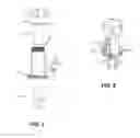
DESCRIPTION OF THE FIGURES
Attention is now directed to several drawings the illustrate features of the present invention.
FIG. 1 shows an embodiment of the present invention in exploded view.
FIG. 2 shows the embodiment of FIG. 1 assembled.
Several illustrations have been provided to aid in understanding the present invention. The scope of the present invention is not limited to what is shown in the figures.
DESCRIPTION OF THE PREFERRED EMBODIMENTS
The present invention is a refueling device that when mounted to a marine fuel tank facilitates refueling and minimizes the propensity for both spit-back and well back while simultaneously allowing a free flowing open pathway through which vapors generated by the refueling event may pass unencumbered.
The device consists of two parts that can be made from metal or composite materials and has several features that have specific functions during the refueling event.
The first part of the device is an exterior body 1 of the spout. The body is designed with a flange 12 as to enable attachment to a fuel tank exterior surface using fasteners. The exterior body 1 of the spout has a thread 8 or tabs at the uppermost part to which a fuel cap 3 can be fastened for sealing purposes. The exterior body of the spout has sufficient mass to enable the attachment of hose barb fittings 5, 6 for the purpose of conveying refueling or venting fuel vapors.
The second part of the device is an interior sleeve 2 of the spout. The interior sleeve of the spout crates a chamber through which refueling or venting fuel vapors may be conveyed separated from the fuel tank interior for the purpose of escape during refueling or venting. The interior sleeve 2 of the spout mates to the interior diameter of the exterior body 1 of the spout and has an internal diameter that takes a typical refueling nozzle by a clearance dimension of greater than approximately 1/32″ and smaller than approximately ¼″ of the total nozzle exterior diameter. This small clearance creates a physical barrier to minimize raw fuel splash commonly known as spit-back or well back. The interior sleeve 2 of the spout has an upper flange 9 that contains smaller holes 10 that in total make up the same area as approximately a ⅝″ diameter hole. The flange holes 10 provide an unencumbered escape path from the chamber created by the mating together of the exterior body of the spout and the interior sleeve of the spout, for fuel vapors generated during the refueling event or normal tank venting.
The lower part of the device is a ball valve with a housing 4 and a ball 7 that prevents any backflow. The present invention includes the following features:
A chambered mountable marine fuel tank refueling spout device
A spit-back and well-back barrier method
A pathway for refueling vapors
A pathway for venting vapors
Several descriptions and illustrations have been presented to aid in understanding the present invention. One with skill in the art will realize that numerous changes and variations may be made without departing from the spirit of the invention. Each of these changes and variations is within the scope of the present invention.
Claims
We claim:1. A fuel tank mounted refueling device comprising:
a cylindrical body having a lower flange adapted to allow direct attachment of the body to a marine tank, the body having an upper threaded portion configured to receive and secure a fuel cap;
a sleeve of smaller diameter than the body adapted to be inserted into the body, the sleeve having an upper flange with a plurality of vent holes;
said sleeve having an inner diameter of greater than 1/32 but less than ¼ inch the diameter of a standard refueling nozzle.
2. The fuel tank mounted refueling device of claim 1 wherein said plurality of holes has a total area of ⅝ inch.
3. The fuel tank mounted refueling device of claim 1 further comprising a lower section attachable to the body that includes a housing with a ball valve.
4. The fuel tank mounted refueling device of claim 1 further comprising a lower and upper hose nipple.
5. The fuel tank mounted refueling device of claim 1 wherein the body and sleeve are molded plastic.
6. The fuel tank mounted refueling device of claim 2 further comprising a lower section attachable to the body that includes a housing with a ball valve.
7. The fuel tank mounted refueling device of claim 6 further comprising a lower and upper hose nipple.
8. The fuel tank mounted refueling device of claim 7 wherein the body and sleeve are molded plastic.
9. A fuel tank mounted refueling device comprising, in combination:
an outer filling body attachable to a fuel tank outer surface;
a removable sleeve insertable into the outer filling body having an inner diameter not greater than ¼ inch larger than a standard refueling nozzle;
a plurality of holes in an upper region of the sleeve having a total area of approximately ⅝ inch.
10. The fuel tank mounted refueling device of claim 9 further comprising a a lower section attachable to the outer filling body that includes a housing with a ball valve.
11. A method of providing a fuel tank mounted refueling device comprising:
providing a cylindrical body having a lower flange adapted to allow direct attachment of the body to a marine tank, the body having an upper threaded portion configured to receive and secure a fuel cap;
providing a sleeve of smaller diameter than the body adapted to be inserted into the body, the sleeve having an upper flange with a plurality of vent holes, said sleeve having an inner diameter of greater than 1/32 but less than ¼ inch the diameter of a standard refueling nozzle.
12. The method of claim 11 wherein said plurality of holes has a total area of ⅝ inch.
13. The method of claim 11 further comprising providing a lower section attachable to the body that includes a housing with a ball valve.
14. The method of claim 11 further comprising providing a lower and upper hose nipple.
15. The method of claim 11 wherein the body and sleeve are molded plastic.
Images & Drawings included:

Sources:
- United States Patent and Trademark Office - verify current appl. status at the USPTO↗
Recent applications in this class:
- » 20230347731 2023-11-02
Fuel type identifying gas cap - » 20230339310 2023-10-26
Closing system for vehicle supply system - » 20230173913 2023-06-08
Method and system for determining the closure status of a fuel tank closure - » 20230135107 2023-05-04
Fuel cap for vehicle having locking structure generating sound interval - » 20230128430 2023-04-27
Fuel cap - » 20230087162 2023-03-23
Driving device for energy replenishment port visor member - » 20220402356 2022-12-22
System for controlling vehicle - » 20220227223 2022-07-21
Fully-integrated, fluid flow-control module designed for installation within an ISO filler neck of a top-fill def tank - » 20220227222 2022-07-21
Fuel filler cap - » 20220219527 2022-07-14
Fuel filler pipe
Recent applications for this Assignee:
- » 20110308662 2011-12-22
Marine fuel tank ullage system - » 20110088648 2011-04-21
Rigid primer bulb pump - » 20110083629 2011-04-14
Rigid primer bulb pump