Forward putting golf putter
US20150375063A1
2015-12-31
13/694,397
2012-11-29
Abstract:
A golf putter is constructed with a relatively large diameter putter shaft and a heavy putter head. Said putter shaft has two gripping areas with thin tape and a ball retriever attaches at the end. Said golf putter head consists of a semi-circular body with a flat sole and a central sole runner. A large head neck seats on slight left of the center of gravity of said putter head. Two symmetrical wing stabilizers also locate on top of said putter head. A letter “T” is marked on the top of said putter head for aiming purpose. Said putter shaft diverges from the vertical line by at least 25 degrees. This golf putter is used in a unique forward putting way with side-saddle manner. A high degree of hole-in can be achieved.
Assignee:
- KUNG CHI YANG 1 🇨🇦 Surrey, Canada
Interested in similar patents?
Get notified when new applications in this technology area are published.
Classification:
A63B53/007 » CPC main
Golf clubs Putters
A63B53/0487 » CPC further
Golf clubs; Heads for putters
A63B53/00 IPC
Golf clubs
A63B53/04 IPC
Golf clubs Heads
Description
BACKGROUND OF THE INVENTION
1. Field of the Prior Art
The present invention relates to a golf putter and a putting method which is different from the conventional putter head configuration and the two-hands sideway putting method in the game of golf.
2. Description of the Prior Art
A conventional golf putter consists of an elongated slope face of the putter head or a semi-circular or fork type sole body attaches to one end of a small diameter of putter shaft. When a golfer putts a golf ball on the green, he stands sideway with two hands holding the putter. A golfer strikes a ball from the right (left) side of his body to the left (right) side of his body for a right-handed (left-handed) putt towards the hole. This method of putting encounters many problems. These problems cannot be easily corrected due to the nature of putting and putter head configuration. These problems include: a) incorrect depth judgement by using a single eye (lazed eye) sighting which is lacking in three dimensional judgement, b) pulling/pushing problems due to a curvature swing, c) a long suspension point from the spinal bone of a golfer to the putter head which causes a less control and low accuracy, d) less pendulous movement, e) a small forgiven putting area due to the way of curvature swing, f) an unstable swing due to due to a small shaft diameter, a small head neck connected area, and a relatively light weight of putter head, g) unsteady gripping hand due to a rubber material in nature, h) co-ordination problem due to unequal size hand muscles which controlled by two different part of human brain, and i) lack of three dimensional control during the swing due to six points of body-hand-putter connection system. (Appendix I List of Prior Art Cited by Applicant)
My previous invention which was filed on Jul. 10, 1998 (Des 431,850) corrected some of problems as mentioned as on the previous paragraph and improved the game of golf putting. However, some of shortcomings and problems of previous invention still exited. These shortcomings included a) the elongated shape of putter head is unstable during backwards swing, b) the head neck location is too close to the head putting face, c) a small diameter of putter shaft produces an unstable swing, d) the degree of divergence of putter shaft from the vertical is too small to strike the ball, e) the head-neck and putter head body connection is too much of abrupt transition, f) a small diameter of head neck is too small to hold steadily which causes a twisting motion during swing, g) a thick rubber made gripping area cannot be held firmly, h) the weight of putting head is too light to swing steadily, i) lack of putting aiming line at the top of putter head, j) lack of guide line to indicate the position of ball lie, k) lack of ball retriever, l) no neck ridge is allow by the new rule, and l) no neck recess is allow by the new rule. The differences of Yang's old designed golf putter and the present invention are summarized on the Table 1. This present invention is followed by the new requirement of golf club which is stated in the “Rule of Golf” (USGA 2012).
A new feature of said golf putter is added. A golf ball retriever is attached at the end of the putter shaft. Said ball retriever can also be replaced with a flat end adoptor with the player's choice.
Said golf putter is used in a side-saddle putting manner with two separated gripping hand on a jumbo gripping area. For a right-handed golfer, the left hand holds the upper grip area and functions as a suspension point for a pendular swing, while the right hand holds the lower gripping area and function as a striking hand. The left foot is placed at the base line as that of said golf head lie. The right foot is at one-foot behind the base line at the middle of base line between the left foot and said putter head. This putting posture forms a letter of “T”. This foot stance provides a steady standing posture and create an adequate room for the backwards swing motion which is needed for a long distance putting. While prepare for striking, the putter head places right behind the golf ball lie. The putter head neck is perpendicular to the sole of putter head and forms a letter of “T” to the ground. While striking, the right eye of the golfer is right on the top of the golf ball. The letter of “T” mark on the top of said putter head aim the target putting line. The right hand grips the lower gripping area and do a proper backwards swing before striking the ball forward. The whole unit of said golf
| TABLE 1 |
| The differences of Yang's old golf putter and the |
| present invention |
| PRESENT | |||
| FEATURES | OLD PUTTER | INVENTION | |
| a. Shape of putter | elongated | semi-circular | |
| b. head necks location | center front | left of gravity | |
| center of head | |||
| c. diameter of putter shaft | <30 mm | >38 mm | |
| d. degree of divergence | >10 | >25 | |
| e. head neck-head body | absence | present | |
| extended connection | |||
| f. diameter of head neck | <20 mm | >25 mm | |
| g. two gripping areas | thick rubber | thin-tape | |
| h. putter head weight | <750 g | >750 g | |
| i. “T” letter on the top | absence | present | |
| of putter head | |||
| j. lines for ball location | absence | present | |
| k. ball retriever | absence | present | |
| l. neck ridge | present | absence | |
| m. neck recess on neck ridge | present | absence | |
putter and two gripping hands move forward together towards the target hole. This forward motion starts at the moment of said putter head struck the ball. This forward putting motion with two eyes sighting ensure the putt will be on a straight line to the hole. This putter putting involved these three “T” letter setting as shown in Appendix IL The present invented golf putter is also called a 3-T putter. By using this present invention, a high percentage of hole-in rate and a high degree of consistency of golf putting can be achieved.
SUMMARY OF THE INVENTION
The present invented golf putter is designed to be used in a forward putting with two eyes sighting in a side-saddle manner.
Said invented golf putter is characterized with a large golf shaft and with a heavy putter head. The shaft has two large gripping areas. Said golf putter consists of a heavy semi-circular sole body with a flat sole and a central sole runner. Said golf shaft has two separated large gripping areas with a thin layer of tape on it. One end of said putter head shaft connects to the neck of putter head which locates at left side of the middle line of the center of gravity of the putter head. The other end of said putter shaft attachs with a ball retriever for an easy ball retrieving after ball-in.
The diameter of said putter shaft with a relatively large diameter of head neck provide a firm and twisting-free swing movement. The projection of the straight part of the shaft on to the vertical plane through the toe and heel of said putter head diverges from the vertical by at least 25 degrees which is required by the golf association. Two wing stabilizers are located at the top of semi-circular sole body head. These stabilizers improves the stability of forward and backwards of striking motion.
The flat striking of said putter head is perpendicular to the ground at the address position. Two lines of ball location indicator locate at the middle of the top of said putter head. A connecting area which is larger than the diameter of the head neck between the putter head neck and the top of said putter head is constructed. This enlarged connecting area improve the stability of forward and backwards swings.
A first letter “T” is marked on the top of semi-circular sole body for aiming the putting line. During putting setting, the head neck to the semi-circular sole forming a second “T” letter to the ground, while a putting stand posture between the two feet and ball location forms a third “T” letter to the putting line. This putting setting provide a big room for a backwards swing, especially for a long distance putting. As a result, a high percentage of hole-in and a high degree of game joy due to two eyes sighting can be achieved. Because of 3 “T” letters involving in putter club construction and putting stand posture, this new invention is also called “The 3 T Putter”.
NOVELTY OF INVENTION
The novelty of said invention and putting method can be summarized as below:
- 1. The weight of said putter head is no less than 750 g which is twice of the weight of conventional putter head. This heavy golf putter head gives players a steady backwards and forward swings.
- 2. An off-center head neck connection to the top of semi-circular sole body creates a balance swing motion due to the divergence of said putter shaft from the vertical plane.
- 3. A large diameter of putter shaft and a firm gripping of right hand on the large gripping area with a thin tape rapping provide a steady and much controllable swing. In a conventional two-hand sideways putting due to its small diameter of golf shaft, a torque problem of swing is commonly encountered.
- 4. The degree of said golf shaft divergence is set at 25 degrees when the putter is in its address position. This large degree of divergence provides a proper address position for golfs left hand to hold the top of the putter shaft gripping area.
- 5. A large diameter of head neck and neck-head and neck-head body connection area create a strong one-piece unit of said golf putter. This one-piece unit feeling enhance greatly a high degree of putting consistence and accuracy.
- 6. An unique design of 3 “T” aiming setting for said golf putter provides a high degree of putting consistency and a high percentage of hole-in rate.
- 7. Two lines of ball lying position indicator ensure the striking right at the sweet sport of said putter head.
- 8. An ball retriever system attaches at the end of said golf shaft of putter increase especially those of senior golf player, pleasure of golf game.
BRIEF DESCRIPTION OF THE DRAWINGS
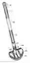
FIG. 1 is a top perspective 3-D general view of a golf putter;
FIG. 2 is a rear elevational view thereof;
FIG. 3 is a front elevational view thereof;
FIG. 4 is a top plan view thereof;
FIG. 5 is a bottom plan view thereof;
FIG. 6 is a right side elevational view of FIG. 1;
FIG. 7 is a left side elevational view of FIG. 1;
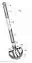
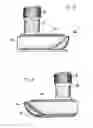
FIG. 8 is an enlarged top perspective view of a second embodiment of said golf putter as disclosed in FIG. 1, The shaft shown fragmented for ease of illustrations;
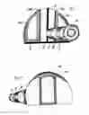
FIG. 9 is a rear elevational view of FIG. 8;
FIG. 10 is a front elevational view of FIG. 8;
FIG. 11 is a top plan view of FIG. 8;
FIG. 12 is a bottom plan view of FIG. 8;
FIG. 13 is a left side elevational view of FIG. 8; and
FIG. 14 is a right side elevational view of FIG. 8.
FIGS. 8, 9, 10, 13 and 14 disclose the shaft broken away due to indeterminate length.
REFERENCE NUMBERS IN DRAWINGS
- 4 golf ball retriever
- 6 grip
- 8 putter shaft
- 10 head neck
- 12 connecting area between head neck to the top putter head
- 14R wing stabilizer (right)
- 14L wing stabilizer (left)
- 16 putter head face
- 18 “T” marker on the top of head face area
- 20 “T” marker in the middle of the top of putter head
- 22 sole runner
- 24R indicator line for the right side of ball lying location
- 24L indicator line for the left side of ball lying location
- 26 semi-circular sole body putter head
DETAILED DESCRIPTION OF THE INVENTION
FIG. 1 illustrates a to perspective 3-D general view of invented golf putter. It is constructed with a putter shaft 8 marking with two separated jumbo gripping areas 6 and a putter head with semi-circular in shape 26 which has two wing stabilizers 14R and 14L on it. A golf ball retriever 4 is attached at the top end of said putter shaft 8. Said putter shaft 8 diverges at the divergence point 125 mm distance or less from the bottom of sole runner 22 at least 25 degrees of divergence from the vertical plane. FIGS. 2 and 3 illustrate a rear and a front elevational view of said invented golf putter. FIGS. 4 and 5 illustrate a top and a bottom plan view of said invented golf putter. FIGS. 6 and 7 is a right side and a left side elevational view of said invented golf putter.
FIG. 8 is an enlarged top perspective view of a second embodiment of said golf putter as disclosed in FIG. 1, the shaft shown fragmented for ease of illustrations. A ball retriever is attached at the top end of said shaft for easy ball retrieving after ball hole-in. The diameter of said ball retriever hole is equal or less than the diameter of the golf ball. Two opposite U shape notches are located at the rim of said ball retriever. The depth of ball retriever hole is greater than half of the diameter of golf ball. The thickness of the rim of said ball retriever is equal to or less than 5 mm. Two U notches provide an easy removal of the golf ball.
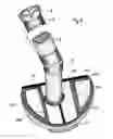
A large diameter of said putter shaft 8 has two separated jumbo gripping areas 6 with a thin layer of tape for a firm gripping. The projection of the straight part of the shaft on to the vertical plane through the toe and heel diverges from the vertical by at least 25 degrees which is required by the golf association around the world. The diameter of the putter shaft 8 is no less than 38 mm. This large putter shaft 8 is connected to a semi-circular sole body 26 which is heavier than 750 g through a relatively large putter head neck 10. Said putter head neck is no less than 28 mm in diameter. This large putter shaft 8 and said putter neck head 10 provide a firm and a twisting-free swing movement. This steady movement is enhanced by a connecting area 12 between said putter head neck 10 to the top of putter head.
Two wing stabilizers 14R 14L are located at the top of said semi-circular sole body 26. These wing stabilizer ensures the stabilization of forward and backwards swing movement during the ball striking. A sole runner 22 is located at the bottom of center of said semi-circular sole body 26. This sole runner 22 ensures the lowest of the center of gravity of semi-circular sole body 26. Said sole runner is also function to reduce the chance of ground choking during ball striking.
The flat striking of said putter head face 16 is perpendicular to the ground at the address position. Two lines 24R 24L of ball lie location indicator of golf ball on the top of said putter head are marked. For a high degree of hole-in rate, three “T” letters putting set-up is designed for this present invention. The first “T” letter marker is located at the top of putter head face area 18 and the middle of the top of said semi-circular sole body putter head 26. The second “T” letter is established between the head neck to said semi-circular sole which is perpendicular to the ground. The third “T” letter is formed for a player's putting posture among the left foot toe, right foot toe and the ball lie location. The left foot toe of player places at the left corner of “T” letter, while the golf ball lies at right corner of “T” letter forming a base line. The right foot toe of player places at middle of “T” letter around 14 inches behind the base line. This putting posture provides a big room for long distance putting.
This new invention is only used for two eyes sighting with a forward arm movement putting method. Two eyes sighting creates a three dimensional feeling which is important for a distance reading. One hand putting reduces the coordination problem of right side brain and left side brain communication. By using this new invention, a high degree of hole-in rate and high degree of game joy can be achieved.
FIG. 1 is a top perspective 3-D general view of a golf putter;
FIG. 2 is a rear elevational view thereof;
FIG. 3 is a front elevational view thereof;
FIG. 4 is a top plan view thereof;
FIG. 5 is a bottom plan view thereof;
FIG. 6 is a right side elevational view of FIG. 1;
FIG. 7 is a left side elevational view of FIG. 1;
FIG. 8 is an enlarged top perspective view of a second embodiment of said golf putter as disclosed in FIG. 1, The shaft shown fragmented for ease of illustrations;
FIG. 9 is a rear elevational view of FIG. 8;
FIG. 10 is a front elevational view of FIG. 8;
FIG. 11 is a top plan view of FIG. 8;
FIG. 12 is a bottom plan view of FIG. 8;
FIG. 13 is a left side elevational view of FIG. 8; and
FIG. 14 is a right side elevational view of FIG. 8.
FIGS. 8, 9, 10, 13 and 14 disclose the shaft broken away due to indeterminate length.
I claim: the golf putter design for a golf game as shown
Claims
I claim:1. The ornamental design for a forward putting golf putter, as shown and described:
Description
FIG. 1 is a top perspective 3-D general view of a golf putter;
FIG. 2 is a rear elevational view thereof;
FIG. 3 is a front elevational view thereof;
FIG. 4 is a top plan view thereof;
FIG. 5 is a bottom plan view thereof;
FIG. 6 is a right side elevational view of FIG. 1;
FIG. 7 is a left side elevational view of FIG. 1;
FIG. 8 is an enlarged top perspective view of a second embodiment of said golf putter as disclosed in FIG. 1, The shaft shown fragmented for ease of illustrations;
FIG. 9 is a rear elevational view of FIG. 8;
FIG. 10 is a front elevational view of FIG. 8;
FIG. 11 is a top plan view of FIG. 8;
FIG. 12 is a bottom plan view of FIG. 8;
FIG. 13 is a left side elevational view of FIG. 8; and
FIG. 14 is a right side elevational view of FIG. 8.
FIGS. 8, 9, 10, 13 and 14 disclose the shaft broken away due to indeterminate length.
Images & Drawings included:


Sources:
- United States Patent and Trademark Office - verify current appl. status at the USPTO↗
Recent applications in this class:
- » 20250161764 2025-05-22
Golf Putter - » 20250121260 2025-04-17
ADJUSTABLE LENGTH PUTTER - » 20250121259 2025-04-17
ADJUSTABLE LENGTH PUTTER - » 20250108269 2025-04-03
GOLF PUTTER - » 20250099819 2025-03-27
GOLF PUTTER - » 20250032863 2025-01-30
Golf Club With Off-Axis Grip - » 20250018253 2025-01-16
PUTTER - » 20250018252 2025-01-16
Putter - » 20240123294 2024-04-18
PUTTER, PUTTING STROKE-SELECTION SYSTEM, AND METHOD - » 20240082650 2024-03-14
PUTTER ASSEMBLY HAVING AN IMAGE SENSOR AND DISPLAY ASSOCIATED THEREWITH