Quake plug
US20150380190A1
2015-12-31
14/316,924
2014-06-27
✅ Patent granted
US 9,269,516 B2
2016-02-23
-
-
Michael Zarroli
2034-09-16
Abstract:
An original apparatus that will react and shut off a main fluid source during a severe earthquake. A steel ball is held at an elevated position by a secured magnet within the housing. It is a preferred embodiment that all materials, for the exception of the steel ball are made of a non-magnetic substance, so that no internal parts interfere with the operation of the apparatus. In the event of a severe earthquake, the seismic vibrations will cause the steel ball to shake and break away from the magnet. Gravity will cause it to fall down. The steel ball will then fall onto the slide trigger. The weight of the steel ball and slide trigger will be pushed down completely and the bottom portion of the slide trigger shall make contact and engage a momentary switch. The momentary switch, in the engaged position will send direct current voltage to a normally open motorized ball valve and cause it to close. Preventing fluid to pass through said ball valve. The apparatus can be reset by manually pulling upward the lift handle towards the top cap. This will allow for the weight of the steel ball to be lifted off the momentary switch and get magnetically attached back to the magnet. Resulting in the momentary switch to disengage and the voltage will seize to power the normally open motorized ball valve, causing it to go back to its normally open state. Thus allowing the fluid to pass through the ball valve. This apparatus can be used repetitively.
Assignee:
- Steve Javir Solis 1 🇺🇸 Montclair, CA, United States
Applicant:
Interested in similar patents?
Get notified when new applications in this technology area are published.
Classification:
H01H35/14 IPC
Switches operated by change of a physical condition Switches operated by change of acceleration, e.g. by shock or vibration, inertia switch
H01H35/006 » CPC further
Switches operated by change of a physical condition Switches operated by mechanical overload condition, e.g. transmitted force or torque becoming too high
H01H35/144 » CPC main
Switches operated by change of a physical condition; Switches operated by change of acceleration, e.g. by shock or vibration, inertia switch operated by vibration
H01H35/141 » CPC further
Switches operated by change of a physical condition; Switches operated by change of acceleration, e.g. by shock or vibration, inertia switch Details
Y10T137/0753 » CPC further
Fluid handling Control by change of position or inertia of system
H01H35/00 IPC
Switches operated by change of a physical condition
F16K17/36 » CPC further
Safety valves; Equalising valves, e.g. pressure relief valves actuated in consequence of extraneous circumstances, e.g. shock, change of position
Description
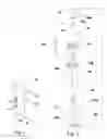
A steel ball 13 is magnetically held at an elevated position by a ring magnet 11, which is secured in place by a screw 12, which is held in place by a threaded hole 10A into the top cap 10, within the housing 15; in FIG. 2. In the event of a severe earthquake, the seismic vibrations will cause the steel ball 13 to shake and break away from the ring magnet 11. Gravity will cause the steel ball 13 to fall onto the slide trigger 14, it will be pushed down completely and the bottom portion of the slide trigger 14 shall make contact and engage a momentary switch 16; in FIG. 4. The momentary switch 16 will need to be connected to direct current. A transformer connected to an alternating current source. Or direct to batteries. Having both power sources will give redundancy to the apparatus in the event that there is a power outage during the earthquake. The momentary switch 16, in the engaged position will send voltage to a normally open motorized ball valve and cause it to close; FIG. 6. Preventing fluid to pass through said ball valve. Once the apparatus has been placed in the standby or ready state. In other words reset by manually pulling upward the lift handle 14A towards the top cap 10 in FIG. 3. The steel ball 13 will magnetically attract back to the ring magnet 11. The weight of the steel ball 13 and slide trigger 14 will be lifted off the momentary switch 16, causing the momentary switch 16 to disengage and the voltage will seize to power the normally open motorized ball valve, thus causing it to go back to its normally open state and allow the fluid to flow through. A preferred embodiment of the invention is that the parts 10, 14, 15, 17 be made of a non-magnetic substance so that those objects do not interfere with the ring magnet 11 and steel ball 13 in FIG. 2. The housing 15 must be mounted vertically such as in FIG. 1. Meaning the top cap 10 is above the housing 15. Therefore the bottom cap 17 will sit lower than the housing 15. The housing 15 should be made at an elongated distance to give chance for the steel ball 13 and slide trigger 14 to move freely in an upward and downward motion between the magnet 11 and the momentary switch 16. The slide trigger 14 should be installed loosely, so that it may move freely in an upward or downward motion, into the housing 15, followed by the lift handle 14A inserted into the slot for handle 15A and then the through hole 14B, using an adhesive compound to secure it in place with the slide trigger 14. Preventing it from coming apart and combining the two pieces as one, so that it will move as one piece in an upward or downward motion. The steel ball 13 is to be installed loosely, so that it may move freely in an upward or downward motion. The momentary switch 16 is to be installed into the center of the bottom cap 17 via a through hole 17A and be secured in place by a nut 18.
DESCRIPTION OF DRAWINGS
FIG. 1—Assembled front angle side view
FIG. 2—Exploded side view
FIG. 3—Front sectional view in the standby position
FIG. 4—Front sectional view in the moved position
FIG. 5—Front perspective sectional view
FIG. 6—Block diagram
10 Top Cap
10A Threaded hole for screw #12
11 Ring magnet
11A Through hole for screw #12
12 Screw
13 Steel ball
14 Slide trigger
14A Lift handle
14B Through hole for lift handle #14A
15 Housing
15A Slot for handle
16 Momentary switch
17 Bottom Cap
17A Through hole for momentary switch #16
18 Nut for momentary switch #16
18A Through hole for momentary switch #16
Claims
I claim:1. An original apparatus wherein said will react to seismic vibrations caused by a severe earthquake and close a constant incoming fluid source.
2. The original apparatus of claim 1 wherein said but not limited to housing 5 be mounted in a vertical position.
3. The original apparatus of claim 1 wherein said but not limited to housing 15, top cap 10, slide trigger 14, bottom cap 17 be composed of a non-magnetic substance.
4. The original apparatus of claim 1 wherein said but not limited to having a flat, circular in shape, magnet with a hole in the center.
5. The original apparatus of claim 1 wherein said but not limited to steel ball 13 be composed of steel.
6. The original apparatus of claim 5 wherein said but not limited to shape of the steel ball 13 be completely round.
7. The original apparatus of claim 6 wherein said but not limited to steel ball 13 be installed loosely in the housing 15, so that it may move freely in an upward or downward motion.
8. The original apparatus of claim 1 wherein said the slide trigger 14 but not limited to its unique shape and dimensions, having the top portion an indentation matching the opposite shape of the steel ball 13 and having a cylinder rounded body, matching the housing 15, having a smaller diameter stem like center protruding downward with a through hole 14b for the lift handle 14a to be installed will move freely as one, in a upward or downward motion inside of the housing 15.
9. The original apparatus of claim 8 wherein said but not limited to slide trigger 14 be installed loosely, so that it may move freely in an upward or downward motion.
10. The original apparatus of claim 1 wherein said housing 15 is but not limited to being elongated and cylinder in shape that has 2 elongated slots exact opposite of each other having the same width and height to allow the lift handle 14a to move freely in a upward or downward motion.
11. The original apparatus of claim 1 wherein said but not limited to momentary switch 16 will send direct current voltage once engaged and stops sending the direct current voltage once disengaged.
12. The original apparatus of claim 1 wherein said but not limited to can be reset manually once in the activated position.
13. The original apparatus of claim 1 wherein said but not limited to can be used repeatedly.
Images & Drawings included:


Sources:
- United States Patent and Trademark Office - verify current appl. status at the USPTO↗
Recent applications in this class:
- » 20200185172 2020-06-11
Intelligent fuseless switch with vibration detection - » 20140216909 2014-08-07
Mechanical vibration switch - » 20130278363 2013-10-24
Device comprising a cantilever and scanning system - » 20120048691 2012-03-01
Automatic vibrational electrical switch device - » 20110126329 2011-05-26
Device comprising a cantilever and scanning system - » 20110042188 2011-02-24
Vibration switch and circuit using the same - » 20090242365 2009-10-01
SWINGING LEAD SWITCH FOR AN ELECTRONIC DEVICE - » 20090183973 2009-07-23
Vibration switch - » 20090166160 2009-07-02
MULTI-LEVEL MICRO-SWITCH - » 20090057110 2009-03-05
VIBRATION SWITCH