Optical transmission device
US20160006512A1
2016-01-07
14/766,852
2014-02-20
✅ Patent granted
US 9,564,974 B2
2017-02-07
WO; PCT/JP2014/054019; 20140220
WO; WO2014/129539; 20140828
Nathan Curs
Oblon, McClelland, Maier & Neustadt, L.L.P.
2034-02-20
Abstract:
Provided is an optical transmission device for transmitting and receiving a multilevel-modulated optical signal, including: a plurality of transmission frame processors (212 to 214, 222 to 224) for generating transmission frame signals accommodating a plurality of client signals that are each subjected to error correction processing and scrambling/descrambling processing; and a digital modulator/demodulator (215) for mapping the transmission frame signals that are input to and output from the plurality of transmission frame processors to a multilevel signal and performing digital modulation/demodulation, in which the plurality of transmission frame processors each have a function of shifting a phase of a pattern between a plurality of transmission frames to be mapped to a multilevel signal and be digitally modulated/demodulated.
Assignee:
- Mitsubishi Electric Corporation 2,856 🇯🇵 Chiyoda-ku, Japan
- MITSUBISHI ELECTRIC CORPORATION 3,549 🇯🇵 Chiyoda-ku, Tokyo, Japan
Applicant:
Interested in similar patents?
Get notified when new applications in this technology area are published.
Classification:
H04B10/516 IPC
Transmission systems employing electromagnetic waves other than radio-waves, e.g. infrared, visible or ultraviolet light, or employing corpuscular radiation, e.g. quantum communication; Transmitters Details of coding or modulation
H04B10/5161 » CPC further
Transmission systems employing electromagnetic waves other than radio-waves, e.g. infrared, visible or ultraviolet light, or employing corpuscular radiation, e.g. quantum communication; Transmitters; Details of coding or modulation Combination of different modulation schemes
H04B10/612 » CPC further
Transmission systems employing electromagnetic waves other than radio-waves, e.g. infrared, visible or ultraviolet light, or employing corpuscular radiation, e.g. quantum communication; Receivers; Coherent receivers for optical signals modulated with a format different from binary or higher-order PSK [X-PSK], e.g. QAM, DPSK, FSK, MSK, ASK
H04J3/1652 » CPC further
Time-division multiplex systems in which the time allocation to individual channels within a transmission cycle is variable, e.g. to accommodate varying complexity of signals, to vary number of channels transmitted; Fixed allocated frame structures Optical Transport Network [OTN]
H04J3/16 IPC
Time-division multiplex systems in which the time allocation to individual channels within a transmission cycle is variable, e.g. to accommodate varying complexity of signals, to vary number of channels transmitted
H04L1/00 IPC
Arrangements for detecting or preventing errors in the information received
H04L1/0042 » CPC further
Arrangements for detecting or preventing errors in the information received by using forward error control; Arrangements at the transmitter end Encoding specially adapted to other signal generation operation, e.g. in order to reduce transmit distortions, jitter, or to improve signal shape
H04L27/362 » CPC further
Modulated-carrier systems; Carrier systems characterised by combinations of two or more of the types covered by groups , , or; Amplitude- and phase-modulated carrier systems, e.g. quadrature-amplitude modulated carrier systems; Modulator circuits; Transmitter circuits Modulation using more than one carrier, e.g. with quadrature carriers, separately amplitude modulated
H04B10/40 » CPC main
Transmission systems employing electromagnetic waves other than radio-waves, e.g. infrared, visible or ultraviolet light, or employing corpuscular radiation, e.g. quantum communication Transceivers
H04B10/61 IPC
Transmission systems employing electromagnetic waves other than radio-waves, e.g. infrared, visible or ultraviolet light, or employing corpuscular radiation, e.g. quantum communication; Receivers Coherent receivers
H04L27/36 IPC
Modulated-carrier systems; Carrier systems characterised by combinations of two or more of the types covered by groups , , or; Amplitude- and phase-modulated carrier systems, e.g. quadrature-amplitude modulated carrier systems Modulator circuits; Transmitter circuits
H04J14/06 » CPC further
Optical multiplex systems Polarisation multiplex systems
H04B10/5561 » CPC further
Transmission systems employing electromagnetic waves other than radio-waves, e.g. infrared, visible or ultraviolet light, or employing corpuscular radiation, e.g. quantum communication; Transmitters; Details of coding or modulation; Phase or frequency modulation; Digital modulation, e.g. differential phase shift keying [DPSK] or frequency shift keying [FSK] Digital phase modulation
H04B10/25 » CPC further
Transmission systems employing electromagnetic waves other than radio-waves, e.g. infrared, visible or ultraviolet light, or employing corpuscular radiation, e.g. quantum communication Arrangements specific to fibre transmission
H04L27/34 » CPC further
Modulated-carrier systems; Carrier systems characterised by combinations of two or more of the types covered by groups , , or Amplitude- and phase-modulated carrier systems, e.g. quadrature-amplitude modulated carrier systems
H04J2203/0089 » CPC further
Aspects of optical multiplex systems other than those covered by; Provisions for broadband connections in integrated services digital network using frames of the Optical Transport Network [OTN] or using synchronous transfer mode [STM], e.g. SONET, SDH Multiplexing, e.g. coding, scrambling, SONET
H04B10/556 IPC
Transmission systems employing electromagnetic waves other than radio-waves, e.g. infrared, visible or ultraviolet light, or employing corpuscular radiation, e.g. quantum communication; Transmitters; Details of coding or modulation; Phase or frequency modulation Digital modulation, e.g. differential phase shift keying [DPSK] or frequency shift keying [FSK]
H04J2203/006 » CPC further
Aspects of optical multiplex systems other than those covered by; Provisions for broadband connections in integrated services digital network using frames of the Optical Transport Network [OTN] or using synchronous transfer mode [STM], e.g. SONET, SDH; Operations, administration and maintenance [OAM] Fault tolerance and recovery
Description
TECHNICAL FIELD
The present invention relates to an optical transmission device for transmitting and receiving a multilevel-modulated optical signal.
BACKGROUND ART
Standards for an optical signal for realizing large-capacity and long-haul communication are defined in the Optical Transport Network (OTN) as specified in ITU-T G.709. Among those, an OTN maintenance signal is formed of, for example, a repeating pattern such as ODU AIS (all “1”s), OCI (repeating “0110”), or LCK (repeating “0101”). In addition, in order to prevent signal degradation on a transmission path, such an OTN maintenance signal is specified to be subjected to scrambling operation before being output (see, for example, Non Patent Literature 1).
Further, there is disclosed an example of a 100 G long-haul transceiver for performing error correction processing for long-haul transmission and transmitting and receiving a polarization multiplexed QPSK signal (see, for example, Non Patent Literature 2).
CITATION LIST
Non Patent Literature
[NPL 1] Recommendation ITU-T G.709/Y.1331 (December 2009) “Interface for the Optical Transport Network (OTN)”
[NPL 2] OIF-MSA-100 GLH-EM-01.1, Optical Interface Forum, Sep. 20, 2011
SUMMARY OF INVENTION
Technical Problem
However, the related art has the following problem.
In a transmission system, in which independent optical channel transport unit—k (OTUk) frames of a plurality of systems are subjected to time-division multiplexing, the following problem arises when the related art is applied to perform mapping to a multilevel signal.
Every OTN maintenance signal has a fixed pattern even after scrambling. Accordingly, for example, in a case where 100 G OTU4 signals of two systems are mapped to a 200 G polarization multiplexed 16 QAM signal, when the 100 G signals are the same maintenance signals in both of the systems, a pattern having the same value for two consecutive bits is mapped to a 200 G polarization multiplexed 16 QAM pattern.
With this, even when the signal is randomized by the scrambling, the fixed pattern is output as a result, which may cause degradation of transmission characteristics.
The present invention has been made in order to solve the above-mentioned problem, and it is an object of the present invention to provide an optical transmission device capable of preventing performance degradation in an optical communication system using a multilevel (e.g., polarization multiplexed 16 QAM scheme) signal of several hundred-Gbps or, more, even at the time of transmission of data having a repeating or periodic pattern, such as an OTN maintenance signal.
Solution to Problem
According to one embodiment of the present invention, there is provided an optical transmission device for transmitting and receiving a multilevel-modulated optical signal, including: a plurality of transmission frame processors for generating transmission frame signals accommodating a plurality of client signals that are each subjected to error correction processing and scrambling/descrambling processing; and a digital modulator/demodulator for mapping the transmission frame signals that are input to and output from the plurality of transmission frame processors to a multilevel signal and performing digital modulation/demodulation, in which the plurality of transmission frame processors each have a function of shifting a phase of a pattern between a plurality of transmission frames to be mapped to a multilevel signal and be digitally modulated/demodulated.
Advantageous Effects of Invention
The optical transmission device according to the one embodiment of the present invention has the function of shifting the phase of the pattern between the plurality of transmission frames to be mapped to the multilevel signal and be digitally modulated/demodulated. Thus, it is possible to obtain the optical transmission device capable of preventing performance degradation in an optical communication system using a multilevel (e.g., polarization multiplexed 16 QAM scheme) signal of several hundred-Gbps or more, even at the time of transmission of data having a repeating or periodic pattern, such as an OTN maintenance signal.
BRIEF DESCRIPTION OF DRAWINGS
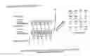
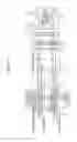
FIG. 1 is a diagram illustrating a configuration of an optical transmission device according to a first embodiment of the present invention.
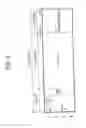
FIG. 2 is a diagram illustrating a format of an OTUk frame to be processed by OTU4 framers of the optical transmission device according to the first embodiment of the present invention.
FIG. 3 is a diagram illustrating a format of an OTUkV frame to be processed by FEC processing circuits of the optical transmission device according to the first embodiment of the present invention.
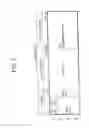
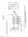
FIG. 4 is a diagram illustrating a symbol transition in polarization multiplexed 16 QAM at the time of transmission of an OTN maintenance signal (ODU-AIS) in the optical transmission device according to the first embodiment of the present invention.
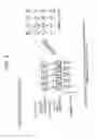
FIG. 5 is a diagram illustrating a symbol transition in polarization multiplexed 16 QAM at the time of transmission of an OTN maintenance signal (ODU-LCK) in the optical transmission device according to the first embodiment of the present invention.
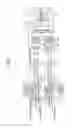
FIG. 6 is a diagram illustrating a configuration of an optical transmission device according to a second embodiment of the present invention.
DESCRIPTION OF EMBODIMENTS
Now, a description is given of an optical transmission device according to preferred embodiments of the present invention with reference to the drawings.
First Embodiment
FIG. 1 is a diagram illustrating a configuration of an optical transmission device according to a first embodiment of the present invention. For example, as a scheme for transmitting an optical signal, in order to realize an optical communication system realizing high-speed and long-haul transmission, such a scheme is adopted that information having a large number of bits is transmitted in a 1-symbol time period by combining quadrature amplitude modulation such as 16 quadrature amplitude modulation (16 QAM) with polarization multiplexing using polarization channels (X polarization and Y polarization). In addition, with in-phase and quadrature phase components for multilevel modulation and the X polarization and Y polarization for polarization multiplexing, eight kinds of signal components are transmitted.
FIG. 1 illustrates an exemplary case where 100 G signals of two systems are transmitted and received by 200 G polarization multiplexed 16 QAM. The optical transmission device illustrated in FIG. 1 includes OTU4 framers 11 and 12 for processing a 100 G OTU signal, a 200 G transceiver 21 for processing a 200 G signal, an E/O 31 for converting an electrical signal into an optical signal, and an O/E 32 for converting an optical signal into an electrical signal.
The OTU4 framers 11 and 12 respectively include the following components.
-
- OTU4 frame generation/termination units 111 and 121 for 100 G signals #1 and #2
- Maintenance generation signal processors 112 and 122 for the 100 G signals #1 and #2
- OTU4 MLD units 113 and 123 for interfacing with the 200 G transceiver 21 by multiple lane distribution (MLD)
Further, the 200 G transceiver 21 includes the following components.
-
- OTU4 MLD units 211 and 221 for 100 G systems #1 and #2 for interfacing with the OTU4 framers 11 and 12 by the MLD
- Memories (FIFOs) 212 and 222 capable of temporarily storing an OTU4 frame to shift a frame phase
- TEC processing circuits 213 and 223 for the 100 G systems #1 and #2
- Scramblers/descramblers 214 and 224 for the 100 G systems #1 and #2
- A digital modulator/demodulator 215 for mapping a signal output from the scramblers 214 and 224 to symbols of an optical signal and performing digital modulation/demodulation processing
- A DA converter (DAC) 216 for generating a modulated optical signal (analog)
- An AD converter (ADC) 226 for converting a modulated optical signal (analog) into a digital signal
Herein, the memory (FIFO) 212, the FEC processing circuit 213, and the scrambler/descrambler 214, and the memory (FIFO) 222, the FEC processing circuit 223, and the scrambler/descrambler 224 correspond to a plurality of transmission frame processors arranged respectively to a plurality of client signals.
FIG. 2 is a diagram illustrating a format of an OTUk frame to be processed by the OTU4 framers 11 and 12 of the optical transmission device according to the first embodiment of the present invention. More specifically, the OTUk frame illustrated in FIG. 2 is formed of the following components.
-
- A payload for storing actual information data such as a client signal
- A frame alignment overhead (FA OH) for frame synchronization
- An OTUk OH and optical channel data unit-k overhead (ODUk OH) for maintenance and monitoring information
- An optical channel payload unit-k overhead (OPUk OH) for payload mapping
- An FEC redundant area for storing information of an error correction code for correcting bit errors caused due to deterioration in an optical quality after transmission
A Reed-Solomon code (hereinafter referred to as “RS code”) is usually used as an error correction code. Note that, in general, a part formed of FA OH, OTUk OH, ODUk OH, and OPUk OH is called “overhead”.
On the other hand, FIG. 3 is a diagram illustrating a format of an OTUkV frame to be processed by the FEC processing circuits 213 and 223 of the optical transmission device according to the first embodiment of the present invention. As illustrated in FIG. 3, for example, an FEC redundant area is extended as compared with the FEC redundant area of FIG. 2 to enhance error correction performance, to thereby realize long-haul transmission.
FIG. 4 is a diagram illustrating a symbol transition in polarization multiplexed 16 QAM at the time of transmission of an OTN maintenance signal (ODU-AIS) in the optical transmission device according to the first embodiment of the present invention. Only symbols having pairs of two consecutive bits having the same value make transitions. It is assumed that as illustrated in the left part of FIG. 4, after the ODU-AIS signal (all “1”s) is subjected to scrambling, a fixed pattern of “10 10 11 01 00” is obtained. In other words, as a result of calculating “EXOR” of “ODU-AIS signal (fixed value)xPRBS (fixed value)”, as indicated by “(A)” of FIG. 4, the same patterns are obtained in both of the two systems.
When the 100 G signals of the two systems (200 G) having a uniform frame phase are transmitted by the polarization multiplexed 16 QAM, symbol map data is as illustrated in the lower left part of FIG. 4. When this data is represented on a constellation map, symbols are mapped at positions surrounded by the broken line in the diagram of the right part of FIG. 4. In other words, only four symbol points from a top-left symbol point to a right-bottom symbol point make transitions.
Similarly, FIG. 5 is a diagram illustrating a symbol transition in polarization multiplexed 16 QAM at the time of transmission of an OTN maintenance signal (ODU-LCK) in the optical transmission device according to the first embodiment of the present invention. Only symbols having pairs of two consecutive bits having the same value make transitions. It is assumed that as illustrated in the left part of FIG. 5, after the ODU-LCK signal (repeating “0101”) is subjected to scrambling, a fixed pattern of “00 11 01 00 10” is obtained.
When the 100 G signals of the two systems (200 G) having a uniform frame phase are transmitted by the polarization multiplexed 16 QAM, symbol map data is as illustrated in the lower left part of FIG. 5. When this data is represented on a constellation map, symbols are mapped at positions surrounded by the broken line in the diagram of the right part of FIG. 5. In other words, only four symbol points from a top-left symbol point to a right-bottom symbol point make transitions.
Accordingly, in the first embodiment, the FIFOs 212 and 222 are arranged individually for the respective 100 G systems so that the phase of the OTU4V frame to be output in the form of the optical signal is shifted for each 100 G system. With this configuration, the pattern at the time of transmission of the OTN maintenance signal is shifted for each 100 G system, and hence it is possible to prevent the occurrence of the fixed patterns at the optical-symbol level, which occur in FIG. 4 and FIG. 5. In other words, it is possible to provide the optical transmission device capable of preventing the performance degradation even at the time of transmission of data having a repeating or periodic pattern, such as an OTN maintenance signal.
As described above, according to the first embodiment, the memory (FIFO) capable of temporarily storing the OTU4 frame to shift the phase of the frame is arranged in the 200 G transceiver for each 100 G system. As a result, the pattern at the time of transmission of the OTN maintenance signal can be shifted for each 100 G system, and hence it is possible to provide the optical transmission device capable of preventing the performance degradation.
Second Embodiment
FIG. 6 is a diagram illustrating a configuration of an optical transmission device according to a second embodiment of the present invention. As compared with the configuration of FIG. 1 according to the first embodiment, the configuration of FIG. 6 according to the second embodiment differs in that the FIFOs 212 and 222 are removed, and that a mechanism for changing a seed value for generating a pseudo-random pattern is added into each of the scramblers/descramblers 214 and 224. Other components and functions are the same as those of the first embodiment described above.
For example, in ITU-T G.709, at the end of the FA OH of the OTUkV frame illustrated in FIG. 3, each frame is initialized with an all-“1”s seed value. Thus, when the seed value for initialization is changed for each 100 G system, the value of the pseudo-random pattern is shifted as a result.
In this manner, in the second embodiment, the mechanism for changing the seed value for generating the pseudo-random pattern for each 100 G system is arranged in each of the scramblers/descramblers 214 and 224. Accordingly, the value of a random signal can be varied for each 100 G system, and hence it is possible to prevent the occurrence of the fixed patterns at the optical-symbol level, which occur in FIG. 4 and FIG. 5. In other words, it is possible to provide the optical transmission device capable of preventing the performance degradation even at the time of transmission of data having a repeating or periodic pattern, such as an OTN maintenance signal.
As described above, according to the second embodiment, the mechanism for changing the seed value for generating the pseudo-random pattern for each 100 G system is arranged in each of the scramblers/descramblers of the 200 G transceiver for each 100 G system. As a result, the pattern at the time of transmission of the OTN maintenance signal can be shifted for each 100 G system, and hence it is possible to provide the optical transmission device capable of preventing the performance degradation.
Note that, the configuration having the two systems is described in the first and second embodiments described above, but it is apparent that similar effects can be acquired even in a configuration having three or more systems by configuring the optical transmission device in a similar manner. Further, the example of the mapping to the polarization multiplexed 16 QAM signal is described in the first and second embodiments described above, but it is apparent that similar effects can be acquired even when the optical transmission device is configured to perform mapping to another type of multilevel signal such as a 64 QAM signal.
Claims
1. An optical transmission device for transmitting and receiving a multilevel-modulated optical signal, comprising:
a plurality of transmission frame processors for generating transmission frame signals accommodating a plurality of client signals that are each subjected to error correction processing and scrambling/descrambling processing; and
a digital modulator/demodulator for mapping the transmission frame signals that are input to and output from the plurality of transmission frame processors to a multilevel signal and performing digital modulation/demodulation,
wherein the plurality of transmission frame processors each have a function of shifting a phase of a pattern between a plurality of transmission frames to be mapped to a multilevel signal and be digitally modulated/demodulated.
2. An optical transmission device according to claim 1, wherein the plurality of transmission frame processors each comprise a memory for shifting a phase of each of the plurality of client signals, and perform the error correction processing and the scrambling/descrambling processing on the each of the plurality of client signals whose phase is shifted by the memory, to thereby shift the phase of the pattern between the plurality of transmission frames to be mapped to the multilevel signal and be digitally modulated/demodulated.
3. An optical transmission device according to claim 1, wherein the plurality of transmission frame processors each change a seed value for generating a pseudo-random pattern in the scrambling/descrambling processing, to thereby shift the phase of the pattern between the plurality of transmission frames to be mapped to the multilevel signal and be digitally modulated/demodulated.
Images & Drawings included:
Sources:
- United States Patent and Trademark Office - verify current appl. status at the USPTO↗
Similar patent applications:
- » 20160241332
RECEPTION DEVICE, TRANSMISSION DEVICE, OPTICAL TRANSMISSION DEVICE, OPTICAL TRANSMISSION SYSTEM, AND MONITORING METHOD - » 20050163177
Semiconductor laser device, optical transmission device, optical transmission system, electronic device, control device, connector, communication device, and optical transmission method and data transmission and reception method - » 9667775
SEMICONDUCTOR LASER DEVICE, OPTICAL TRANSMISSION DEVICE, OPTICAL TRANSMISSION SYSTEM, ELECTRONIC DEVICE, CONTROL DEVICE, CONNECTOR, COMMUNICATION DEVICE, AND OPTICAL TRANSMISSION METHOD AND DATA TRANSMISSION AND RECEPTION METHOD - » 20240319443
OPTICAL TRANSMISSION DEVICE, OPTICAL TRANSMISSION DEVICE PRODUCTION METHOD, AND OPTICAL CABLE SYSTEM - » 20220278767
Optical transmission device, optical transmission system and method of updating the optical transmission device - » 20140270631
Method and device for manufacturing optical transmission device, and optical transmission device - » 20150303653
Optical device, optical transmission device, optical reception device, hybrid laser and optical transmission apparatus - » 20090201965
Vertical-cavity surface-emitting laser, module, optical transmission device, optical transmission system, free space optical communication device, and free space optical communication system - » 20090169218
Optical transmission device, optical transmission system, and bandwidth control method - » 20070223922
Optical transmission device, optical transmission method, and computer product
Recent applications in this class:
- » 20250293780 2025-09-18
SPECTRALLY INTERLEAVED OPTICAL TRANSCEIVERS - » 20250293779 2025-09-18
OPTICAL COMMUNICATION DEVICE, OPTICAL DEVICE, AND ASSEMBLING METHOD FOR OPTICAL DEVICE - » 20250293778 2025-09-18
Signal Adapter Device and Network System - » 20250286624 2025-09-11
OPTOELECTRONIC ASSEMBLY - » 20250274197 2025-08-28
SYSTEMS AND METHODS FOR FREE SPACE OPTICAL INJECTION LOCKING - » 20250260491 2025-08-14
TRANSMITTER SHIELDING FOR OPTICAL TRANSCEIVERS - » 20250253953 2025-08-07
METHOD OF MAKING A CARBON DOPED ELECTROMAGNETIC WAVE ABSORBER - » 20250253952 2025-08-07
INSERTION/REMOVAL STRUCTURE, INSERTION/REMOVAL METHOD, AND OPTICAL TRANSMISSION APPARATUS - » 20250233669 2025-07-17
ELECTRONIC COHERENT TRANSCEIVER FOR HIGH BANDWIDTH DATA COMMUNICATION - » 20250233668 2025-07-17
SYSTEMS AND METHODS FOR PERFORMING TESTS AND MEASUREMENTS USING AN OPTICAL TRANSCEIVER
Recent applications for this Assignee:
- » 20250292172 2025-09-18
PROCESS PLAN PREPARATION ASSISTANCE APPARATUS, PROCESS PLAN PREPARATION ASSISTANCE SYSTEM, AND PROCESS PLAN PREPARATION ASSISTANCE METHOD - » 20250274374 2025-08-28
TEST INFORMATION MANAGEMENT SYSTEM, TEST INFORMATION MANAGEMENT APPARATUS, INFORMATION CONVERSION APPARATUS, AND TEST INFORMATION MANAGEMENT METHOD - » 20250274054 2025-08-28
POWER CONVERSION DEVICE - » 20250273527 2025-08-28
SEMICONDUCTOR DEVICE, POWER CONVERSION APPARATUS, AND METHOD OF MANUFACTURING SEMICONDUCTOR DEVICE - » 20250271218 2025-08-28
HEAT TRANSFER PIPE, HEAT EXCHANGER, PIPE EXPANDING TOOL, PIPE EXPANDING DEVICE, METHOD FOR CONNECTING HEAT TRANSFER PIPE AND PIPE, AND METHOD FOR MANUFACTURING HEAT EXCHANGER - » 20250266224 2025-08-21
GAS INSULATION DEVICE - » 20250244260 2025-07-31
DETERIORATION DISCRIMINATING DEVICE AND DETERIORATION DISCRIMINATING METHOD - » 20250242846 2025-07-31
TRAIN INFORMATION MANAGEMENT APPARATUS, TRAIN INFORMATION MANAGEMENT SYSTEM, AND TRAIN INFORMATION MANAGEMENT METHOD - » 20250234465 2025-07-17
VEHICULAR ELECTRIC POWER CONVERTING DEVICE - » 20250225483 2025-07-10
MACHINE LEARNING APPARATUS, WBS CREATION APPARATUS, AND MACHINE LEARNING METHOD