Dual-spindle machining apparatus
US20160023316A1
2016-01-28
14/790,551
2015-07-02
✅ Patent granted
US 9,969,037 B2
2018-05-15
-
-
John C Hong
Andrew Wilford
2035-10-04
Abstract:
An apparatus for machining a workpiece has a housing having a vertical front wall and first and second side walls extending generally perpendicularly back from outer edges of the front wall, directed horizontally oppositely away from each other, and defining first and second planes themselves delimiting a space. First and second vertical guides on the first and second side walls outside the housing carry first and second vertical slides moveable vertically on the first and second vertical guides of the first and second side walls. First and second horizontal guides on the first and second vertical slides carry first and second horizontal slides movable horizontally on the first and second horizontal guides of the first and second vertical slides between the first and second front work stations and the first and second rear transfer stations.
Assignee:
- EMAG HOLDING GMBH 33 🇩🇪 Salach, Germany
Applicant:
Interested in similar patents?
Get notified when new applications in this technology area are published.
Classification:
B23Q39/048 » CPC main
Metal-working machines incorporating a plurality of sub-assemblies, each capable of performing a metal-working operation the sub-assemblies being arranged to operate simultaneously at different stations, e.g. with an annular work-table moved in steps the work holder of a work station transfers directly its workpiece to the work holder of a following work station
B23P23/02 » CPC main
Machines or arrangements of machines for performing specified combinations of different metal-working operations not covered by a single other subclass Machine tools for performing different machining operations
B23Q2039/002 » CPC further
Metal-working machines incorporating a plurality of sub-assemblies, each capable of performing a metal-working operation Machines with twin spindles
B23Q39/04 » CPC further
Metal-working machines incorporating a plurality of sub-assemblies, each capable of performing a metal-working operation the sub-assemblies being arranged to operate simultaneously at different stations, e.g. with an annular work-table moved in steps
B23Q1/017 » CPC further
Members which are comprised in the general build-up of a form of machine, particularly relatively large fixed members; Frames, beds, pillars or like members; Arrangement of ways Arrangements of ways
B23Q39/024 » CPC further
Metal-working machines incorporating a plurality of sub-assemblies, each capable of performing a metal-working operation the sub-assemblies being capable of being brought to act at a single operating station with a plurality of toolheads per workholder, whereby the toolhead is a main spindle, a multispindle, a revolver or the like with same working direction of toolheads on same workholder consecutive working of toolheads
B23Q2039/004 » CPC further
Metal-working machines incorporating a plurality of sub-assemblies, each capable of performing a metal-working operation Machines with tool turrets
B23Q2230/008 » CPC further
Special operations in a machine tool Machining the middle part and the ends of a workpiece consecutively
Y10T29/49996 » CPC further
Metal working; Method of mechanical manufacture; Shaping one-piece blank by removing material Successive distinct removal operations
Y10T29/5114 » CPC further
Metal working; Plural diverse manufacturing apparatus including means for metal shaping or assembling; Type of machine; Lathe Lathe and tool
Y10T29/5124 » CPC further
Metal working; Plural diverse manufacturing apparatus including means for metal shaping or assembling with means to feed work intermittently from one tool station to another
Y10T29/5135 » CPC further
Metal working; Plural diverse manufacturing apparatus including means for metal shaping or assembling with means to feed work intermittently from one tool station to another Endless belt
Y10T29/5153 » CPC further
Metal working; Plural diverse manufacturing apparatus including means for metal shaping or assembling with turret mechanism Multiple turret
B23Q39/02 IPC
Metal-working machines incorporating a plurality of sub-assemblies, each capable of performing a metal-working operation the sub-assemblies being capable of being brought to act at a single operating station
B23Q39/00 IPC
Metal-working machines incorporating a plurality of sub-assemblies, each capable of performing a metal-working operation
B23Q1/01 IPC
Members which are comprised in the general build-up of a form of machine, particularly relatively large fixed members Frames, beds, pillars or like members; Arrangement of ways
Description
FIELD OF THE INVENTION
The present invention relates to an apparatus for machining a workpiece. More particularly this invention concerns such an apparatus that can drill, lathe, shape or otherwise machine workpieces one after the other.
BACKGROUND OF THE INVENTION
Copending U.S. patent application Ser. No. 13/431,173, which is incorporated herein by reference, describes a machining apparatus comprising a frame defining first and second upper machining stations horizontally offset from each other and respective first and second lower transfer stations underneath the first and second upper machining stations. Respective first and second spindles have respective first and second workpiece grabs and are displaceable vertically on the frame between upper positions with the respective first and second grabs in the respective first and second machining stations and lower positions with the respective first and second grabs in the respective first and second transfer stations. Respective first and second workpiece conveyors extend through the first and second transfer stations for transporting workpieces into and out of the respective transfer stations so that the respective spindles can pick up unmachined workpieces from the respective transfer stations and set machined workpieces down in the respective transfer stations. A holder carries tools and is displaceable on the frame between the first and second machining stations so that while a workpiece is being machined by one of the tools in one of the machining stations a workpiece can be loaded into or unloaded from the grab of the spindle of the transfer station of the other of the machining stations. A chip deflector has first and second parts movable between respective catch positions underneath the respective first and second machining stations and respective parked positions not underneath the respective first and second machining stations such that, when the first and second parts are in their respective parked positions, the spindles are able to move vertically between the respective machining and transfer stations. A horizontal guide is provided on the frame along which the first and second parts of the chip deflector can travel in a straight line to move between the respective catch and parked positions.
Such a machine is relatively efficient, but the travel path of the workpiece between the work spindles is fairly long and complex.
OBJECTS OF THE INVENTION
It is therefore an object of the present invention to provide an improved machining apparatus.
Another object is the provision of such an improved machining apparatus that overcomes the above-given disadvantages, in particular that has a simple travel path for the workpiece.
SUMMARY OF THE INVENTION
An apparatus for machining a workpiece has according to the invention a housing having a vertical front wall and first and second side walls extending generally perpendicularly back from outer edges of the front wall, directed horizontally oppositely away from each other, and defining respective first and second planes themselves delimiting a space. Respective first and second vertical guides on the first and second side walls outside the housing carry respective first and second vertical slides moveable vertically on the first and second vertical guides of the first and second side walls. Respective first and second horizontal guides on the first and second vertical slides carry respective first and second horizontal slides movable horizontally on the first and second horizontal guides of the first and second vertical slides between respective first and second front work stations and first and second rear transfer stations all lying outside the space defined between the planes. Respective first and second holders for tools are provided in the work stations. The first slide, first spindle, first holder, and first stations are to one side of the space and the second slide, second spindle, second holders and second stations are to an opposite side of the space.
Thus the workpiece moves in a simple U-shaped path around the machine housing for machining in the two work stations. Most of the movement can be done by simple movement of the spindles.
The first and second holders cannot move out of the respective first and second front work stations. They typically each include a rotatable mount for a plurality of tools, some of which may even be powered.
According to the invention a conveyor extends through the rear transfer stations and can move workpieces one after the other into the first rear transfer stations, then from the first rear transfer station to the second transfer station, and then out of the second rear transfer station. This conveyor extends past rear wall of the housing.
In accordance with the invention an inverter between the rear work stations can pick workpieces up off the conveyor, turning them over, and redeposit them on the conveyor upside down.
This apparatus with the conveyor can be operated by first picking a first workpiece up with the first spindle in the first rear transfer station and transporting it horizontally parallel to the first side wall into the first front work station, then machining the first workpiece in the first front work station with one of the tools of the first holder, and finally transporting the first workpiece with the first spindle back to the first rear work station and depositing it on the conveyor. Then the first workpiece is displaced by the conveyor from the first rear work station to the second rear work station where it is picked up by the second spindle and transported horizontally parallel to the second side wall into the second front work station where it is machined with one of the tools of the second holder. Finally it is transported by the second spindle back to the second transfer station.
The steps of picking up, machining, and transporting a second workpiece with the first spindle are carried out while picking up, machining, and transporting the first workpiece with the second spindle.
BRIEF DESCRIPTION OF THE DRAWING
The above and other objects, features, and advantages will become more readily apparent from the following description, reference being made to the accompanying drawing in which:
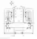
FIG. 1 is a partly schematic front elevational view of the apparatus of this invention; and
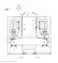
FIG. 2 is a top view of the apparatus.
SPECIFIC DESCRIPTION OF THE INVENTION
As seen in FIGS. 1 and 2, a machining apparatus has a columnar housing 1 of essentially square footprint with planar, vertical, and parallel first and second side walls 2 and 3 defining parallel first and second vertical planes E and F and front and back walls 4 and 26 that are also planar, vertical, horizontally spaced, and perpendicular to the side walls 2 and 3. The side walls 2 and 3 carry respective first and second pairs of horizontally spaced but vertical guide rails 5′ and 5″ on which ride respective first and second vertical slides 12 and 13 that are horizontally elongated and project slightly forward past the front wall 4 and a significantly greater distance, here around four times greater, past the rear wall 26. The vertical slides 12 and 13 can move vertically on the respective side walls 2 and 3 in a vertical direction Z but are horizontally nondisplaceable.
The slides 12 and 13 in turn are provided with respective first and second pairs of vertically spaced and horizontally extending guide rails 16′ and 16″ on which ride respective first and second horizontal slides 14 and 15 that carry respective first and second spindle drives 6 and 7 of standard construction. The horizontal slides 14 and 15 can therefore move horizontally on the respective side walls 2 and 3 in a horizontal direction Y (FIG. 2 only) perpendicular to the vertical direction Z. The spindle drives 6 and 7 carry respective first and second holders or chucks 23′ and 23″ adapted to pick up and hold workpieces 11, and to rotate the gripped workpieces 11 about respective vertical axes A′ and A″.
A stationary traverse beam 24 carries first and second turrets 8 and 9 rotatable about respective horizontal axes parallel to the direction Y and each holding a plurality of tools 10 beneath respective first and second front work stations 20 and 21 each spaced outward in a horizontal direction X from the front end region of the respective side walls 2 and 3. This horizontal direction X is perpendicular to the vertical direction A and other horizontal direction Y.
Rearward in the direction Y from the rear wall 26 of the housing 1 is a conveyor 17 that extends in the horizontal direction X past the rear wall 26 of the housing 1 and that passes through first and second rear transfer stations 18 and 19 aligned rearward in the direction Y from the respective front work stations 20 and 21. This conveyor 17 can be a simple belt conveyor and serves to move workpieces 11 into the transfer station 18, then from the transfer station 18 to the station 19, and thence away from the transfer station 19 as will be described below. The above-described structure is symmetrical to a plane P parallel to the planes E and F and midway therebetween.
Between the stations 18 and 19 is an inverter or flipper 22 capable of picking a workpiece 11 up from the conveyor 17, turning it through 180°, and depositing it back on the conveyor 17 so that, when it gets to the station 19 it is upside-down as compared to its position in the station 18.
The system operates as follows:
Series of workpieces 11 are delivered one after the other in the direction X by stepped operation of the conveyor 18 to the first rear intake/transfer station 18. The first spindle 6 meanwhile is moved to a position directly above the workpiece 11 in the station 18 as shown by dot-dash lines in FIG. 2 and can therefore pick up the workpiece 11 with its grab/chuck 23′.
The spindle 6 then travels forward in the direction Y to the first front work station 20 in which, as is standard, a one of the tools 10 in the first turret 8 is engaged with the workpiece 11 as it and/or the tool 10 are/is rotated, thereby performing a first machining operation on this workpiece 10.
Subsequently the first spindle 6 is moved back to the first rear station 18 where it deposits the partly machined workpiece 10 on the conveyor 17, which then steps the workpiece 10 downstream so that it can be grasped by the inverter 22, turned upside down, and redeposited on the conveyor 17 that, in turns displaces it into the second rear station 19.
The second spindle 7 meanwhile has moved, as the first spindle 6 did before, back into the second rear station 19 to pick up the workpiece 10 and move it into the second front work station 21 where it is machined again, but on the side not worked before in the first station 20.
When this operation is done, the finished workpiece 10 is moved by the second spindle 7 back and deposited in the second rear station 19 onto the conveyor 17 that moves it in the direction X away from the machining apparatus.
The first and second spindles 6 and 7 and inverter 22 as well as the conveyor 17 can all be operating at the same or offset times, so that the machine is kept busy. The travel path of the workpieces is very simple and relatively short, relying on a simple straight-line conveyor and simple straight-line movements of the spindles 6 and 7, so that the only manipulator that is needed is the inverter 22 that flips the workpieces 11. The entire machine can easily be centrally controlled by a computer to mass produce finely machined workpieces, and can be reprogrammed to do a number of tasks, and even to perform a number of different jobs on the workpiece 20 with different tools 10 while in either of the stations 20 or 21.
Claims
I claim:1. An apparatus for machining a workpiece, the apparatus comprising:
a housing having a vertical front wall and first and second side walls extending generally perpendicularly back from outer edges of the front wall, directed horizontally oppositely away from each other, and defining respective first and second planes themselves delimiting a space;
respective first and second vertical guides on the first and second side walls outside the housing;
respective first and second vertical slides moveable vertically on the first and second vertical guides of the first and second side walls;
respective first and second horizontal guides on the first and second vertical slides;
respective first and second horizontal slides movable horizontally on the first and second horizontal guides of the first and second vertical slides between respective first and second front work stations and first and second rear transfer stations all lying outside the space defined between the planes; and
respective first and second holders for tools in each of the work stations, the first slide, first spindle, first holder, and first stations being to one side of the space and the second slide, second spindle, second holders and second stations being to an opposite side of the space.
2. The machining apparatus defined in claim 1, wherein the first and second holders cannot move out of the respective first and second front work stations.
3. The machining apparatus defined in claim 1, further comprising:
a conveyor extending through the rear transfer stations and operable to move workpieces one after the other into the first rear transfer stations, then from the first rear transfer station to the second transfer station, and then out of the second rear transfer station.
4. The machining apparatus defined in claim 3, wherein the conveyor extends past rear wall of the housing.
5. The machining apparatus defined in claim 4, further comprising:
an inverter between the rear work stations for picking workpieces up off the conveyor, turning them over, and redepositing them on the conveyor upside down.
6. A method of operating a machining apparatus having:
a housing having a vertical front wall and first and second side walls extending generally perpendicularly back from outer edges of the front wall, directed horizontally oppositely away from each other, and defining respective first and second planes themselves delimiting a space;
respective first and second vertical guides on the first and second side walls outside the housing;
respective first and second vertical slides moveable vertically on the first and second vertical guides of the first and second side walls;
respective first and second horizontal guides on the first and second vertical slides;
respective first and second horizontal slides movable horizontally on the first and second horizontal guides of the first and second vertical slides between respective first and second front work stations and first and second rear transfer stations all lying outside a space defined between the planes;
respective first and second holders for tools in each of the work stations, the first slide, first spindle, first holder, and first stations being to one side of the space and the second slide, second spindle, second holders and second stations being to an opposite side of the space; and
a conveyor extending through the rear transfer stations,
the method comprising the steps of sequentially:
picking a first workpiece up with the first spindle in the first rear transfer station and transporting it horizontally parallel to the first side wall into the first front work station;
machining the first workpiece in the first front work station with one of the tools of the first holder;
transporting the first workpiece with the first spindle back to the first rear work station and depositing it on the conveyor;
displacing the first workpiece with the conveyor from the first rear work station to the second rear work station;
picking the first workpiece up with the second spindle in the second rear transfer station and transporting it horizontally parallel to the second side wall into the second front work station;
machining the first workpiece in the second front work station with one of the tools of the second holder;
transporting the first workpiece with the second spindle back to the second transfer station.
7. The method defined in claim 6, further comprising the step of:
inverting the first workpiece while conveying it from the first rear transfer station to the second rear transfer station.
8. The method defined in claim 6, further comprising the steps of picking up, machining, and transporting a second workpiece with the first spindle while picking up, machining, and transporting the first workpiece with the second spindle.
Images & Drawings included:
Sources:
- United States Patent and Trademark Office - verify current appl. status at the USPTO↗
Similar patent applications:
Recent applications in this class:
- » 20220379424 2022-12-01
Apparatus for machining hubs for vehicles - » 20200086447 2020-03-19
Machining centre for timepiece components - » 20190184513 2019-06-20
MACHINING DEVICE FOR MACHINING A WORKPIECE NARROW SIDE AND METHOD - » 20130340242 2013-12-26
Method and apparatus for complete machining of a shaft-shaped workpiece - » 20050217441 2005-10-06
Tool holder and method of machining work using this tool holder - » 20050191140 2005-09-01
Method and apparatus for machining a blank from all directions - » 20050076757 2005-04-14
Lathe
Recent applications for this Assignee:
- » 20160346894 2016-12-01
Dual-spindle grinding machine - » 20160278169 2016-09-22
Inductive hardening machine - » 20150018179 2015-01-15
Method and apparatus for changing tools - » 20140326114 2014-11-06
Double-spindle machining apparatus - » 20140157559 2014-06-12
Machining apparatus - » 20140094097 2014-04-03
Dual-spindle grinder - » 20140079500 2014-03-20
Machining apparatus with chip shield - » 20140030969 2014-01-30
Grinding disk and apparatus - » 20130340242 2013-12-26
Method and apparatus for complete machining of a shaft-shaped workpiece - » 20130255066 2013-10-03
Dual-spindle machining apparatus