Beverage Can Closing Member
US20160023802A1
2016-01-28
14/766,941
2012-02-08
Abstract:
The invention relates to a beverage can closing member (99) comprising a frame part (10) that has a frame (11) and is used to open a beverage can by pressing in a lid of the beverage can at a predetermined breaking line, further comprising a covering member (42) to be arranged in an opening of a beverage can, and a locking device (46) which is designed and/or arranged on the covering member (42) and is designed and/or arranged in such a way that the covering member (42) arranged in an opening of a beverage can can be locked in an opening of a beverage can, the covering member (42) being designed in a closure part (40) and/or insertion part which is accommodated in the frame (11) of the frame part (10).
Interested in similar patents?
Get notified when new applications in this technology area are published.
Classification:
B65D2517/0014 » CPC further
Containers specially constructed to be opened by cutting, piercing or tearing of wall portions, e.g. preserving cans or tins; Details; Action for opening container pivot tab and push-down tear panel
B65D2517/0034 » CPC further
Containers specially constructed to be opened by cutting, piercing or tearing of wall portions, e.g. preserving cans or tins; Details; Reclosable openings the tab reclosing the opening by means of the hand grip alone, e.g. rotating hand grip into opening
B65D17/00 IPC
Rigid or semi-rigid containers specially constructed to be opened by cutting or piercing, or by tearing of frangible members or portions
Description
The invention relates to a beverage can closure element according to the generic term in claim 1.
The invention relates to a beverage can lid with a beverage can closure element of this type and a beverage can with a beverage can lid of this type.
Next to bottles, beverage cans are the most important retail packaging for beverages and generally also serve as a drinking vessel. They are primarily used for carbonated beverages such as canned beer and soft drinks.
Beverage cans generally consist of a single-piece, cylindrical container made of aluminum or tinplate, a seamed lid made of aluminum with an oval scored line or rupture line and a riveted metal tab which, when raised, depresses the scored oval into the interior of the can through lever action, thus creating a pouring or drinking opening.
The invention relates to a beverage can closure element which is capable of closing and locking an opening of any type and releasing said opening again, all in a simple manner. The invention relates in particular to a lid for a container such as a beverage can, where the lid consists of plate, preferably tinplate. Beverage cans generally have a rupture line in the lid. An opening tab fixed to the lid can produce a dispensing opening by the action of a rupture lever on the rupture line.
Beverage cans of this type primarily contain liquids such as beer, lemonade, fruit juices, mineral water or similar, but can also be used for sauces, herb mixtures, grated cheese, nuts or similar.
The disadvantage of familiar beverage cans is that they cannot be closed again after opening. This means that there is a risk of residual contents being spilt in the workplace, in vehicles, when playing, etc. Furthermore, contaminants and insects may enter the can.
In WO A1 2010/022951 a beverage can closure element is disclosed according to the preamble of claim 1.
Given the large number of cans sold per year worldwide is a particularly important cost production, a reliable function must be guaranteed.
The invention is therefore based on the object to provide a beverage can closure element which can be manufactured inexpensively, wherein the removal opening easy to close, lock and back is easy to open.
The object of the invention is achieved by a beverage can closure element according to the features of claim 1 or of one of the independent claims.
Advantageous embodiments of the invention are specified in the dependent claims.
According to one embodiment of the invention, a beverage can closure element having a frame having the frame part for opening of a beverage can by pushing a beverage can lid of the beverage can at a predetermined breaking line, and a cover element for location in an aperture of a beverage can and formed on the cover element and/or its associated locking means provided which is formed and/or arranged such that the disposed in an opening of a beverage can cover element is lockable in an opening of a beverage can, wherein the cover element is formed in a closure part and/or insert, which is accommodated in the frame of the frame part.
According to the invention may be incorporated into the frame of the frame part with a clamping connection and/or adhesive bond and/or spraying compound the closure part and/or insert.
According to the invention, the closure part and/or insert may be connected non-positively and/or positively to the frame of the frame part.
According to the invention the closure part and/or insert can be pressed into the frame of the frame part and/or bonded, and/or crimped.
The connection between the closure element and Insert and the frame can be carried out only in some areas.
According to the invention, the closure part and/or insert may be formed from plastic and are injection molded into the frame of the frame part.
The frame element may form the closing part or insert a hybrid part.
According to one embodiment of the invention, a beverage can closure element having a frame having the frame part for opening of a beverage can by pushing a beverage can lid of the beverage can at a predetermined breaking line, and a cover element for location in an aperture of a beverage can and formed on the cover element and/or its associated locking means provided which is formed and/or arranged such that the disposed in an opening of a beverage can cover element is in an opening of a beverage can be locked, wherein the covering element is designed and arranged inside the frame of the frame part, wherein the cover element along a part of its circumference with the frame is connected, and is formed along another part of its periphery, separated from the frame.
According to the invention can be provided for the separation of the cover from the frame one or more breakthrough lines or the cover from the frame along parts portions of the periphery of the cover away.
According to the invention, the cover may be formed of the frame separately along two parts of its circumference.
The break lines can be arranged on opposite sides.
Preferably, the or one of the breakthrough curves between the portion can be provided with the rivet hole and said cover.
In an embodiment with three break-through lines may be formed by a broken line, and the other two may each be adapted to laterally opposite sides.
Alternatively or additionally, according to one embodiment of the invention, a beverage can closure element having a frame having the frame part for opening of a beverage can by pushing a beverage can lid of the beverage can at a predetermined breaking line, and a cover element for location in an aperture of a beverage can and formed on the cover element and/or arranged locking means provided which is designed and/or arranged such that the disposed in an opening of a beverage can cover element is lockable in an opening of a beverage can, wherein the cover element is designed and arranged inside the frame of the frame part, wherein in the cover element a predetermined breaking point and/or opening for receiving a drinking straw is provided.
According to the invention, a film formed to cover the cover element in the predetermined breaking point and be provided opening.
According to the invention, the beverage can closure element comprise an actuator for opening a re-re-closed with the cover element beverage can.
Here, the actuator may be formed as part of the closure part.
Alternatively or additionally, the actuation element may be an extension of the cover extending over a portion of the frame of the frame part, preferably in the direction of rivet hole, and/or may comprise, disposed on said cover layer of material, the actuating element, which preferably has an undercut which is preferably configured and dimensioned such that, for example, a fingernail fits into the undercut to open the back sealed with the cover element beverage can, and/or may be formed the actuator as a nose, a bead or a survey, or in an edge portion of the cover is formed, and/or may be formed as a bladder, a button, a projection or an extension of the operating element, or vehicle which is designed and arranged outside of the frame of the frame part and is connected to the cover element, wherein the bladder button elevation or the extension, preferably in a recess is arranged which is provided in the frame part, and/or may be formed above a surface of the frame part, the actuating element, preferably in the frame part, a slot is provided by the closure element and
Insert extends in order to connect the bladder key lobe or projection of the cover element and/or the actuating element is formed below a surface of the frame part, wherein the actuation of the actuator pressure is exerted on the surface of the frame part.
According to the invention a beverage can closure element having bearing means disposed between the cover element and the actuator.
Here, the supporting means be formed as a groove and/or recess and/or an increase in, extending substantially along a portion of the circumference of the cover at a distance from the cover element and/or which is formed substantially straight.
According to the invention, the beverage can closure element having a securing device, which is constructed and arranged such that it allows the actuation of the actuator in a first position and in a further position preventing the actuation of the actuating element.
According to the invention, the beverage can closure element comprise a further actuating element, which is preferably formed corresponding to the first operation song, wherein the bearing means is preferably formed and arranged between the two actuators.
According to one embodiment of the invention may be provided, which can each be formed in accordance with the embodiments of the invention with a supporting means and arranged two bearing means.
Advantageously, the beverage can closure element may be designed such that an operation should be carried out with two fingers.
This significantly increases safety against unintended opening.
According to the invention, the cover lugs and/or recesses and/or grooves and/or beads have, preferably extending toward the center of the cover from the edge of the cover.
According to the invention, the frame and/or the cover have reinforcements, which are preferably formed as bulges, beads and/or grooves.
According to the invention be formed of a rubber-like material and/or a combination of such materials, the cover element made of metal, a metal alloy and/or plastic and/or.
According to the invention, the frame part may be formed of metal and/or aluminum plate and/or the material of the beverage can.
According to the invention the cover element and/or the frame part sealing lips and/or the sealing has bulges.
According to the invention may be constructed and arranged so the cover, that the cover, when the beverage can closure element is disposed in an opening of a beverage can, between at least two states is elastically deformable, wherein the locking device is arranged on the cover element and configured such that the locking device in at least a condition of the cover the at least two states of the cover element relative to the cover element radially further inside than in at least another one of the at least two states of the cover element is arranged.
In this case, the cover may preferably be elastically deformable by an external force and/or by interaction with the beverage can between the at least two states.
According to the invention may be arranged and/or formed on the underside of the locking device and/or at the top of the cover.
According to the invention the cover element may be formed plate spring-like manner and/or the cover element comprise a surface section which is formed curved in one of the states up and is arched in another of the states to bottom and/or the cover element, at least one and preferably a plurality of having reinforcing ribs and/or reinforcing grooves.
According to the invention the locking means comprise at least one and preferably a plurality of locking elements, and the cover element is preferably designed as a wholly or partially circumferential edge or
Edges and/or as a nasal or
Lugs are formed, and/or the locking means comprise at least one and preferably a plurality of spaced projections on said cover.
According to the invention, the beverage can closure element having a release means and/or an actuator comprising, or vehicle is constructed and arranged such that the locking device is unlocked by actuating the unlocking device and the actuating element, preferably in which by elastic deformation of the cover element in the state, locking means are arranged radially on the inside, and the unlocking the actuation element comprises a preferably arranged on the beverage can closure element or a lever mechanism with one or more arranged on the beverage can closure element wings.
According to the invention the cover is a curved surface or part surface, preferably a curved top surface or part surface, the surface and/or the surface portion is preferably round, oval, trapezoidal with rounded corners, bridge-shaped, groove-shaped, rectangular, square, triangular, polygonal or the like is formed. and/or wherein the cover element has a curved surface or part surface which is directed downwardly, or has a curved top surface, which partially includes a downwardly facing surface, and/or wherein the cover as the locking element has a comprising edge, wherein the edge is a completely or partially circumferential edge, or one or more projecting parts comprises, and/or wherein the cover element has a full or partial circumferential stiffening groove and/or rib, for example, in the form of an offset.
According to the invention the edge of the cover having one or more tabs and/or the cover element may have a flat surface or a protruding from a plane surface, the protruding out of the plane surface is preferably a curved or a multiply curved surface.
According to the invention may comprise the beverage can closure element having a discharge opening for discharging the contents of the beverage can be defined fracture line.
According to the invention may be the beverage can closure element arranged as an opening tab for opening the beverage can by pushing the beverage can lid at the predetermined breaking line and formed and/or the beverage can closure element may be arranged and formed on the can end, that the beverage can closure element after opening of the removal opening, either by turning and/or by folding of the beverage can closure element over the dispensing opening can be arranged in order to cover it and to be closed again, and/or may be arranged and formed the rim of the beverage can closure element that it locks the closure of the dispensing opening in the dispensing opening, is clamped in the dispensing opening or it snaps into place, and/or the storage facility to be constructed in the beverage can lid, preferably as an elevation, curvature, contour, groove and/or groove, the bearing area of the bearing device is further formed preferably on points and/or lines.
According to the invention, the beverage can lid having at least one groove and/or recess for receiving one formed on the beverage can closure element rib bead and/or nose.
According to the invention, the groove and/or recess have a circular shape, wherein the groove and/or recess may be continuous and/or interrupted.
According to the invention, the beverage can lid comprising a bladder for receiving and/or fixing and/or support of the beverage can closure element, wherein the bladder can preferably be kidney-shaped or circular and/or in accordance with the closure element and/or the bladder may preferably have a recess of the bladder is located as seen in the direction of the opening portion.
According to the invention may be characterized under the beverage can closure element of the area of the beverage can lid, preferably in color with red, blue, yellow, green or any other color preferably clearly recognizable and/or other suitable marking.
According to the invention, the beverage can lid a knockout and/or curvature exhibit, which can be adapted to preferably that the beverage can lid at least in the area of the opening section after the production of the beverage can with the beverage can lid after filling the beverage can and after the opening of the can substantially is planar.
According to the invention can be formed at least in the region of the removal opening, the pre-embossing and/or curvature.
According to the invention it can be provided and/or to the beverage can closure element comprises a sealing strip may be provided that is preferably disposed at least partially or completely in a stiffening profile of the beverage can closure element comprises a seal.
According to the invention, the beverage can closure element having a fold line and/or the beverage can closure element be formed of a plurality of materials and preferably have a plastic fuel mass, which may be preferably sprayed in the frame part, and/or the beverage can closure element at least in the cover element and/or in the cover element have plastic tabs.
According to the invention, the beverage can closure element at least in a portion and preferably in the range of the cover element have bimetal and/or be formed of bimetal and/or the beverage can closure element have at least one stiffener, wherein the stiffener can be formed preferably dome-shaped and/or tubular.
According to the invention, the beverage can closure element having a nose which is formed at the edge of the extension.
According to the invention may be one and preferably a plurality of fulcrums formed on the beverage can closure element at least in the beverage can lid with recesses may be preferably designed to receive the points of the hand lever.
According to the invention may be formed in the cover element of the beverage can closure element at least one recess and/or, in the beverage can closure element a bulge may be formed beyond the edge of the opening portion to be covered during reclosing.
According to the invention can be formed in the beverage can closure element and/or the beverage can lid, a peripheral to the cover element and the opening portion of the shaft.
According to the invention, the beverage can closure element have a coating with a sealing lip and/or a sealing bead.
According to the invention, the beverage can closure element, at least one, and preferably a plurality of recesses, said recess (it) is preferably formed as a punched hole (are) more preferably such that a part of the beverage can sealing element extends downwardly so that when reclosed the beverage can at the edge the opening in the beverage can lid engages, is formed at the predetermined breaking line upon opening of the beverage can.
According to the invention there is also provided a beverage can with such a beverage can lid or such beverage can closure element.
According to the invention, the beverage can be made of metal, preferably tinplate, and/or be made of plastic and/or a combination of different materials.
According to the invention, the cover element can be elastically deformable through the external application of force between the at least two states.
According to the invention, the cover element can be elastically deformable through interaction with the beverage can between the at least two states.
According to the invention, the locking mechanism can be configured and/or embodied on the underside of the cover element. The underside of the cover element is the side of the cover element turned towards the contents of the beverage can when the beverage can closure element is configured in the opening of the beverage can to close the beverage can again.
Alternatively or additionally, the locking mechanism can be configured and/or embodied on the upper side of the cover element.
Alternatively or additionally, the locking mechanism can be configured and/or embodied on the upper side of the cover element.
According to the invention, the cover element can be embodied as a disc spring design.
According to the invention, the cover element can exhibit a surface section embodiment which is curved upwards in one of the states and curved downwards in another of the states. Variants and alternatives are conceivable. For example, depressions or level sections or grooves and/or ribs can be included in the curvature. The transition from a level surface to a curved surface or vice versa is also conceivable. The transition from a gentler curvature to a more severe curvature or from a more severe curvature to a gentler curvature is also conceivable.
According to the invention, the cover element can exhibit at least one and preferably several reinforcing ribs and/or reinforcing grooves.
According to the invention, the locking mechanism can exhibit at least one and preferably several closure elements which should preferably be embodied as a completely or partially circumferential rim or rims that run or runs around the cover element and/or as a lug or lugs.
Locking mechanism closure elements of this type can be preferably embodied and configured so that they engage behind the rim of the beverage can opening in the locked state and, consequently, can lock the beverage can closure element in the opening.
According to the invention, the locking mechanism can comprise one and preferably several extensions configured on the cover element.
According to the invention, the cover element can be configured in a ring-like component that encloses the rim of the cover element, whereby extensions are preferably embodied on the cover element, which are accommodated in slots embodied in the ring-like component.
The extensions can act as a locking mechanism in this embodiment of the invention in that they move outwards in a radial direction through the slots of the ring-like component when the cover element is pressed, resulting in the locking of the beverage can closure element in the dispensing opening. In the case of this embodiment of the invention, the cover element and its extensions and the ring-like component should preferably be manufactured with the same material as the beverage can lid and the beverage can. However, it would also be conceivable that the components could be made of other materials, for example and preferably plastic which is compatible with foodstuffs. The components can be made of the same or different materials in this respect.
According to the invention, the beverage can closure element can exhibit an unlocking mechanism embodied and configured so that the locking mechanism is unlocked when the unlocking mechanism is actuated, preferably through elastic deformation of the cover element in the state in which the closure elements are still configured inwards in a radial direction.
This means that the beverage can opening can be cleared again after the unlocking mechanism is actuated. In other words, the elastic deformation of the cover element that occurs during locking can be reversed again with the unlocking mechanism by applying a force to the cover element in such a manner that the cover element reverts from one stable state (i.e. the locking state, for example) to another stable state (i.e. the unlocking state, for example) which corresponds to the state in which the cover element was configured for locking in the opening of the beverage can. The cover element can be removed again from the beverage can opening following unlocking and pivoted into another position to clear the opening again to enable further dispensing of the contents of the beverage can.
According to the invention, the unlocking mechanism can encompass a lever configured on the beverage can closure element or a mechanism with one or more wings configured on the beverage can closure element.
Alternatively or additionally, the reversal of the elastic deformation of the cover element of the beverage can closure element cover element can be achieved by actuating the beverage can closure element itself.
According to the invention, the cover element can exhibit a curved surface or partial surface, preferably an upwardly curving surface or partial surface, whereby the embodiment of the surface and/or partial surface is preferably round, oval, trapezoidal with rounded corners, bridge shaped, groove shaped, rectangular, square, triangular, polygonal or similar.
The curved surface or partial surface of the cover element can, of course, also exhibit any other suitable shape, particularly a shape with rounded corners.
According to the invention, the cover element can exhibit a curved surface or partial surface directed downwards, or exhibit an upwardly curving surface which in part encompasses a surface directed downwards.
According to the invention, the cover element can exhibit a rim as a closure element, whereby the rim is a completely or partially circumferential rim or encompasses one or more projecting parts.
According to the invention, the cover element can exhibit a completely or partially circumferential reinforcing groove and/or reinforcing rib, for example in the form of an offset.
This embodiment has the advantage that the stability of the cover element is enhanced, whereby locking in the dispensing opening is easier to manage and more reliable.
According to the invention, the rim of the cover element can exhibit one or more lugs.
This enables the achievement of better (i.e. simpler) and more reliable locking of the cover element in the dispensing opening.
According to the invention, the cover element can exhibit a level surface or a surface protruding from a level surface, whereby the surface protruding from the level surface is preferably a curved surface or a surface with multiple curves.
The preferred embodiment of the cover element is such that it is the part of the opening tab or the beverage can closure element, which can close the dispensing opening of the beverage can again.
The invention also relates to a beverage can lid with a beverage can closure element according to the invention, preferably with a rupture line defining a dispensing opening for dispensing the contents of the beverage can.
According to the invention, the beverage can closure element can be configured and embodied as an opening tab for opening the beverage can by pressing in the beverage can lid on the rupture line.
This is the preferred embodiment of the invention. Alternatively, the beverage can closure element can also be planned as a component or part separate from an opening tab. It is evident that, according to the invention, the beverage can closure element can also be planned as a part separate from the beverage can. However, an embodiment of the beverage can opening tab as a beverage can closure element according to the invention is preferred. To this end, the beverage can closure element has the double function of an opening tab for the initial opening of the beverage can and an element to close the beverage can again, locking the beverage can closure element in the beverage can opening created by opening the beverage can along the rupture line.
According to the invention, the beverage can closure element can be configured and embodied in such a manner on the beverage can lid that, following opening of the dispensing opening, the beverage can closure element can be configured over the dispensing opening, either through pivoting and/or folding down the beverage can closure element to cover and close the dispensing opening again.
According to the invention, the rim of the beverage can closure element can be configured and embodied in such a manner that it snaps into the dispensing opening (4) when closing the dispensing opening (4), is clamped tightly in the dispensing opening (4) or engages in said.
According to the invention the beverage can lid can at least exhibit a groove and/or depression for the inclusion of a rib, beading and/or lug embodied at the beverage can closure element. This feature can offer the advantage of a better and more space-saving stackability and storage of beverage can lids in the manufacture of beverage cans. According to the invention the groove and/or depression can preferably be embodied circular, whereby the groove and/or depression can be embodied in a continuous and/or interrupted way.
According to the invention the beverage can lid can exhibit a bubble for including the beverage can closure element. This embodiment of the invention offers the advantage that the beverage can closure element cannot simply be pressed through unintentionally, but can be supported by the suitably configured bubble. According to the invention the bubble can preferably be configured kidney-shaped, circular or according to the shape of the closure element. In addition, according to the invention the bubble can preferably exhibit a recess, arranged in the direction of the opening section as viewed from the bubble. This further embodiment has the advantage that the beverage can closure element can be arranged above the opening section of the beverage can lid without being obstructed by the bubble.
According to the invention the area of the beverage can lid below the beverage can closure element (bubble) can be marked, preferably by different colors in red, blue, yellow, green or another preferably clearly recognizable color, by letters, numbers or signs. This embodiment of the invention has the advantage that the consumer can easily recognize whether the beverage can is still new and/or unopened or already reclosed, if no opening of the beverage can be seen, because only in case of the reclosed beverage can will the marked area be visible, as it is covered by the beverage can closure element in case of a new and/or unopened beverage can.
According to the invention the beverage can lid can exhibit a pre-impression and/or curvature, preferably configured such that the beverage can lid is largely level, at least in the area of the opening section after manufacturing the beverage can with the beverage can lid, after filling the beverage can and after opening the beverage can. This embodiment of the invention has the advantage that the beverage can closure element can better reclose the opening section of the beverage can. Alternatively or additionally the beverage can closure element can be embodied such that it exhibits a curvature, corresponding to the curvature of the opening section after opening the beverage can. Alternatively or additionally the beverage can closure element and/or the beverage can lid can be configured in such a flexible way in the area of the opening section that the curvatures of the beverage can closure element and the beverage can lid adapt to the beverage can when reclosing it.
Alternatively or additionally the tolerance ranges of sealing elements could be configured such that possible different curvatures of the beverage can closure element and/or beverage can lid in the area of the opening section when sealing the opening section by the beverage can closure element are within the tolerances. According to the invention the pre-impression and/or curvature can be embodied here at least in the area of the beverage opening.
According to the invention a seal can be included at the beverage can closure element.
According to the invention a sealing band can be provided at the beverage can closure element,
preferably at least partly or completely arranged in a reinforcing profile. The sealing band can be embodied as a coating, for example.
According to the invention the beverage can closure element can exhibit a buckling line. According to the invention the buckling line can be provided by a pinch and/or a depression on the upper and/or lower side of the beverage can closure element to facilitate the deformation for reclosure and/or re-opening of the beverage can.
According to the invention the beverage can closure element is embodied of several materials and preferably exhibits a plastic overmoulding or plastic bubble.
According to the invention the beverage can closure element can exhibit plastic lugs in the cover element.
According to the invention the beverage can closure element can exhibit plastic lugs at least in the cover element.
According to the invention the beverage can closure element can exhibit bimetal on the whole surface or at least in a section and preferably in the area of the cover element and/or it can be embodied of bimetal.
According to the invention the beverage can closure element can at least exhibit reinforcement.
According to the invention the reinforcement can be configured in a dome- and/or tubular shape. The reinforcement can be configured, for example, at the rim of the cover element and/or at the rim of the beverage can closure element. The reinforcement can be configured upward and/or downward, i.e. in the direction of the beverage can lid.
According to the invention the beverage can closure element can exhibit a lug, embodied at the rim of the extension. This embodiment of the invention has the advantage that the beverage can can be opened more easily, as the area of the beverage can closure element which presses on the beverage can lid when opening the beverage can to open the beverage can lid at the predetermined rupture point, is reinforced by the lug and can exert higher pressure on certain points on the area of the predetermined rupture point.
According to the invention at least one and preferably several leverage points can be embodied in the beverage can closure element, whereby in the beverage can lid preferably depressions are embodied for including the leverage point and/or leverage points.
According to the invention conical or continuous leverage points or leverage point of any shape (round/rectangular, any shape, any positioning) can be fit in the tab or the beverage can lid to ensure easier opening by the opening lever. These opening leverage points can, for example, be hidden each in the stamped depressions of the lid and become active only after opening and turning the tab. The leverage points/areas remove the tension from the curvature and can be fit at any point on the lid or tab.
According to the invention at least a depression can be embodied in the cover element of the beverage can closure element. This embodiment of the invention has the advantage that by including depressions the tension on the “tip” of the dome of the cover element can be reduced and the height can be minimized. The depressions can have any shape considered to be suitable by a person skilled in the art. For example, in the middle of the cover element an essentially round depression and/or an essentially circular groove and/or depression arranged around the center of the cover element can be included.
According to the invention a curvature can be configured in the beverage can closure element, exceeding the rim of the opening section to be covered when reclosed. This embodiment of the invention has the advantage that the curvature will exceed the opening rim when reclosing the beverage can, resulting in an “upward movement” of the rims. By suitable constructional elements of the tab, the opening element can be placed higher and an opening mechanism can be provided.
According to the invention a circumferential undulation can be embodied around the cover element and/or the opening section in the beverage can closure element and/or the beverage can lid. This embodiment of the invention has the advantage that a good sealing of the reclosed beverage can can be provided by a simple way with low manufacturing costs.
According to the invention the beverage can closure element can exhibit a coating with a sealing lip and/or sealing bead. According to the invention the coating and/or the sealing lip and/or the sealing bead can be embodied of plastic and/or silicone and/or rubber.
According to the invention the beverage can closure element can exhibit a spreader ring at its rim, preferably exhibiting knobs and/or lugs.
According to the invention the predetermined rupture line in the beverage can lid can include a ligament for the opening section which keeps the opening section of the beverage can lid connected to the beverage can lid after opening the beverage can.
According to the invention the beverage can closure element can exhibit a spreader ring and/or knobs for sealing the beverage can closure element against the beverage can lid when reclosing the beverage can, whereby preferably at least a wider knob or lug and/or at least a continuous material area is included which is provided opposite to an area of the beverage can lid when reclosing the beverage can, at which the opening section of the beverage can lid will remain connected with the beverage can lid after opening the beverage can.
According to the invention the beverage can closure element can exhibit at least one and preferably several recesses, whereby the recess (it) is (are) preferably embodied as cut-out, in addition preferably such that a part of the beverage can closure element goes downward in such a way that when redo sing the beverage can, it catches at the rim of the opening in the beverage can lid which was formed at the predetermined rupture line when opening the beverage can.
According to the invention, the reopening mechanism can consist of a rupture lever exhibited by the beverage can closure element which is used as a reopening lever, or that the reopening mechanism consists of one or more wings fixed to the opening tab or embodied as a single part with the opening tab, whereby the wing(s) is/are manufactured from the same material as the opening tab or a material other than that of the opening tab.
Alternatively or additionally, the reopening mechanism can also consist of the configuration of an opening mechanism on the other side of the opening tab opposite the rupture lever which can be used as an auxiliary opening mechanism or main opening mechanism, whereby the rim of the opening tab or one or more wings can be used for reopening.
According to the invention, the upper side of the opening tab or beverage can closure element can, in terms of shape and surface quality, be designed so that it can be used for advertising purposes, images, logos, numbering, etc.
The invention also relates to a beverage can with a beverage can lid according to the invention and/or a beverage can closure element according to the invention.
According to the invention, the beverage can can be manufactured from metal, preferably tinplate, and/or plastic and/or a combination of different materials.
According to the invention, the beverage can can be used for beverages, granular and/or powdered products, sauces, nuts or other products.
The beverage can lid according to the invention can, for example, be produced in a manner where the lid is initially pressed in a conventional manner, but forming the opening tab so that it can be inserted into the dispensing opening and locked and that it can be raised easily out of the dispensing opening again to clear the opening. The rim provided for locking can be embodied as a completely or partially circumferential rim in this respect, or consist of one or more projecting parts, and/or a completely or partially circumferential reinforcing groove can be provided which ensures greater opening tab stability and better locking in the dispensing opening. Furthermore, the opening tab can be pressed in a manner where one or more wings is/are moulded as a single part or that one or more wings is/are fixed to the opening tab.
When handling the beverage can according to the invention, the said beverage can can be opened using the opening tab, after which the opening tab is pivoted or folded through 180° to close and lock the dispensing opening, whereby the closure elements of the beverage can closure element are, through deformation of a beverage can closure element surface, moved outwards in a radial direction relative to the surface to lock the dispensing opening, and the mechanism for reversing this deformation is actuated by moving the closure elements inwards in a radial direction relative to the surface to clear the opening again.
In some embodiments of the invention, an upwardly curving surface of the opening tab can be pressed downwards to lock the dispensing opening in a manner in which the curvature reverses, whereby the opening tab snaps into the dispensing opening and locks the lid, or that the upwardly curving surface is pressed downwards in a manner in which the curvature is lessened or becomes completely flat, whereby the opening tab stretches and the rim of the opening tab is pressed outwards, and whereby the opening tab snaps into the dispensing opening and locks the lid.
In some embodiments of the invention, the lug or lugs can clamp on the rim of the opening tab or engage in this position to lock the dispensing opening.
The opening tab or the cover element can, for example, be pressed downwards to lock the dispensing opening, this being realized in a manner that causes the curvatures of the curved surface to reverse (i.e. the upwardly curving surface curves downwards and the downwardly curving surface or partial surface curves upwards), whereby the opening tab or the cover element or the beverage can closure element snaps into the dispensing opening and locks.
The rupture lever can be used as a reopening lever to reopen the beverage can, whereby the rupture lever, which was pivoted together with the opening tab or beverage can closure element, is pressed downwards, whereby the snapped-in rim is pressed inwards again and the curved surface, which was less curved or even flat in the snapped-in state, is pressed upwards again, whereby the opening tab and beverage can closure element are released from the dispensing opening and can be pivoted or folded back.
Alternatively or additionally, an opening mechanism can be provided or used for reopening which is located on the other side of the opening tab opposite the rupture lever, whereby the rim of the opening tab or one or more wings can be used to loosen the opening tab.
The wing(s) can be pressed downwards to reopen the container, whereby the opening tab or the beverage can closure element returns to its original shape, or whereby the wing(s) is/are raised and pulled upwards.
Following opening of the beverage can, the opening tab or beverage can closure element or beverage can closure element can be pivoted or folded and pressed into the dispensing opening. Closure elements can be provided to avoid situations where the opening tab or the beverage can closure element loosens out of the dispensing opening, and a reopening mechanism can be provided to enable clearing of the dispensing opening again.
The opening tab used for reclosing or the beverage can closure element used for reclosing can be accommodated without difficulty in the disc-shaped cavity which opens upwards and is formed between the central lid component and the upper can rim, particularly if the tab or closure element consists of a thin plate stamped part. This means that according to the invention the lid can be produced by conventional machines without the need for major adaptations.
The dispensing opening can be reliably closed and locked, and dirt, dust and pests (i.e. insects) cannot penetrate into the can after it has been opened. The contents can no longer be spilled in appreciable quantities in the workplace, when playing or when travelling in moving vehicles. The subject matter of the invention can even be closed and locked to a degree that prevents the contents of the can being spilled in appreciable quantities if the can topples over. A can equipped in this manner is also very environmentally friendly; as the opening tab or the beverage can closure element used for reclosing is continually connected to the can.
The embodiment of the closure elements is such that the opening tab or beverage can closure element or beverage can closure element snaps into the dispensing opening and locks during reclosing. The opening tab or beverage can closure element should preferably exhibit an upwardly curving surface or partial surface in this respect and should preferably have a circumferential rim which can snap into the dispensing opening. The surface or partial surface can be round, oval, trapezoidal with rounded corners, bridge shaped, groove shaped, rectangular, square, triangular, polygonal or similar, with rounded corners if necessary. The surface or partial surface can also consist of combinations of different shapes (e.g. angular and rounded shapes).
The curved surface or partial surface can also be directed downwards, or the upwardly curving surface can in part exhibit a surface directed downwards. The surface or partial surface directed downwards facilitates reclosing and locking.
Locking can be achieved as follows in the case of some embodiments of the invention: the upwardly curving surface is pressed downwards in a manner in which, due to this deformation, the curved surface presses the rim of the opening tab or beverage can closure element or beverage can closure element outwards in a radial direction; the opening tab or the beverage can closure element snaps into the dispensing opening and shuts the lid. The engaging rim can be a completely or partially circumferential rim, or consist of one or more projecting parts. A completely or partially circumferential reinforcing groove (e.g. in the form of an offset, a depression or an elevation) can ensure greater stability of the opening tab or beverage can closure element and improved engaging in the dispensing opening.
In the case of some embodiments of the invention, the reopening mechanism can involve use of a rupture lever (i.e. the lever used to break open the rupture line) as a reopening lever, whereby the rupture lever which was pivoted or folded back together with the opening tab or beverage can closure element is pressed downwards, whereby the snapped-in and locked rim is pressed inwards again and the curved surface, which is directed downwards in the snapped-in and locked state, is pressed upwards again. The opening tab or beverage can closure element releases itself from the dispensing opening in this manner. The opening tab or beverage can closure element can therefore be pivoted or folded back to permit further emptying of the beverage can. The curved surface, which was pressed downwards for locking, can also be less downwardly curving or even flat in the locked state.
Alternatively, the locking mechanism can consist of an embodiment of the dispensing opening rim which enables firm clamping or engaging of the opening tab or beverage can closure element or beverage can closure element in the dispensing opening during reclosure. The rim of the opening tab or beverage can closure element or beverage can closure element exhibits one or more lugs for locking in the dispensing opening.
Alternatively, the reopening mechanism can consist of one or more wings fixed to the opening tab or beverage can closure element or embodied as a single part with the opening tab or beverage can closure element. The wing(s) is/are manufactured from the same material as the opening tab or beverage can closure element or a material other than that of the opening tab or beverage can closure element.
The part of the opening tab or beverage can closure element which can reclose the dispensing opening should preferably have a level surface or a surface raised above the level surface. This surface protruding from the level surface can be a curved surface or a surface with multiple curves and can preferably constitute the cover element or a considerable part of the cover element.
Additionally, the upper side of the opening tab or beverage can closure element can, in terms of shape and surface quality, be designed so that it can be used for advertising purposes, images, logos, numbering, etc.
The invention also relates to a container with a closure element or lid according to the invention, whereby the container can be manufactured from an environmentally friendly material such as metal, preferably tinplate, or plastic or a combination of different materials. A container of this type can be used for beverages, granular or powdered products, sauces, nuts or other products.
Where the container is a beverage can, the lid, and particularly the opening tab or beverage can closure element, can exhibit a hole or several holes through which tubular objects (e.g. drinking straws) can be inserted.
The invention also encompasses a process for the manufacture of a lid, whereby the lid is initially pressed in a conventional manner, but forming the opening tab or beverage can closure element so that it can be inserted into the dispensing opening. The opening tab or beverage can closure element exhibits a circumferential rim in this respect which can snap into or engage in the dispensing opening, or be clamped firmly therein. Alternatively the rim of the opening tab or beverage can closure element can exhibit one or more lugs.
The invention also encompasses a process for opening, reclosing and reopening the container. The rupture lever, for example, can be pressed downwards for reopening, whereby the rim locked though snapping, engaging or clamping is released and the opening tab or beverage can closure element can be pivoted or folded back. Alternatively, one or more wings can be provided for opening and also reopening the container to enable release of the opening tab or beverage can closure element.
Although the invention relates in particular to a lid for a beverage can, other applications are also possible, e.g. as a beverage can closure element for temporarily closing bottles or similar containers or as a cover for objects such as camera lenses or similar.
The invention is described in greater detail below on the basis of the embodiment examples illustrated in the figures:
FIG. 1 shows a schematic plan view of a frame part of a beverage can closure element according to a first embodiment of the invention.
FIG. 2 shows a schematic sectional view of the frame part of FIG. 1 along the line II-II of FIG. 1.
FIG. 3 shows a schematic sectional view of the frame part of FIG. 1 along the line of FIG. 1.
FIG. 4 shows a schematic plan view of a closure element of the beverage can closure element according to the first embodiment of the invention, the frame part in FIG. 1 to FIG. 3 is shown.
FIG. 5 shows a schematic sectional view of the closure element of FIG. 4 along the line VV of FIG. 4.
FIG. 6 shows a schematic sectional view of the closure element of FIG. 4 along the line VI-VI of FIG. 4.
FIG. 7 shows a schematic plan view of a frame part of a beverage can closure element according to a second embodiment of the invention.
FIG. 8 shows a schematic sectional view of the frame part of FIG. 7 along the line VIII-VIII of FIG. 7.
FIG. 9 shows a schematic sectional view of the frame part of FIG. 7 along the line IX-IX of FIG. 7.
FIG. 10 shows a schematic plan view of a closure element of the beverage can closure element according to the second embodiment of the invention, the frame part in FIG. 7 to FIG. 9 is illustrated.
FIG. 11 is a schematic sectional view of the closure element of FIG. 10 along the line XI-XI of FIG. 10.
FIG. 12 is a schematic sectional view of the closure element of FIG. 10 along the line XII-XII of FIG. 10.
FIG. 13 shows a schematic plan view of the beverage can closure element according to the first embodiment of the invention, the frame part in FIG. 1 to FIG. 3, and the closure element shown in FIG. 4 to FIG. 6 is illustrated.
FIG. 14 shows a schematic sectional views of the beverage can closure element of FIG. 13 along the line XIV-XIV of FIG. 13, wherein the top and bottom of the frame part, the closure part are shown individually.
FIG. 15 shows a schematic sectional view of the beverage can closure element of FIG. 13 taken along line XV-XV of FIG. 13, with single above the frame part, are shown in the middle of the frame part with the closure part and below is a detail view of the area marked with a dotted circle.
FIG. 16 shows a schematic plan view of a closure element of a beverage can closure element according to a third embodiment of the invention, wherein the edge of the opening of the associated frame part, in which the closing element is received, is illustrated by dashed lines.
FIG. 17 is a schematic sectional view of the closure element of the beverage can closure element of FIG. 16 along the line XVII-XVII of FIG. 16, at the bottom right is a detailed view of the area shown marked with a dotted circle.
FIG. 18 is a schematic sectional view of the closure element of the beverage can closure element of FIG. 16 along the line XVIII-XVIII of FIG. 16, at the bottom right is a detailed view of the area marked with a dotted circle is shown.
FIG. 19 is a schematic sectional view of the closure element of the beverage can closure element of FIG. 16 along the line XIX-XIX of FIG. 16, at the bottom right is a detailed view of the area marked with a dotted circle is shown.
FIG. 20 shows a schematic plan view of a closure element of a beverage can closure element according to a fourth embodiment of the invention, wherein the edge of the opening of the associated frame part, in which the closing element is received, is illustrated by dashed lines.
FIG. 21 is a schematic sectional view of the closure element of the beverage can closure element of FIG. 20 along the line XXI-XXI of FIG. 20, at the bottom right is a detailed view of the area marked with a dotted circle is shown.
FIG. 22 is a schematic sectional view of the closure element of the beverage can closure element of FIG. 20 along the line XXII-XXII of FIG. 20, at the bottom right is a detailed view of the area marked with a dotted circle is shown.
FIG. 23 is a schematic sectional view of the closure element of the beverage can closure element of FIG. 20 taken along the line XXIII-XXIII of FIG. 20, at the bottom right is a detailed view of the area marked with a dotted circle is shown.
FIG. 24 shows a detailed view of a beverage can closure element according to a fifth embodiment of the invention with a beverage can lid, shown in part, corresponding to the detailed view of FIG. 15.
FIG. 25 shows a detailed view of a beverage can closure element of FIG. 24 in a different sectional plane.
FIG. 26 shows a detailed view of a beverage can closure element according to a sixth embodiment of the invention with a beverage can lid, shown in part, corresponding to the detailed view of FIG. 15.
FIG. 27 shows a detailed view of a beverage can closure element of FIG. 26 in a different sectional plane.
FIG. 28 shows a detailed view of a beverage can closure element according to a seventh embodiment of the invention with a beverage can lid, shown in part, corresponding to the detailed view of FIG. 15.
FIG. 29 shows a detailed view of a beverage can closure element of FIG. 28 in a different sectional plane.
FIG. 30 shows a detailed view of a beverage can closure element according to a eighth embodiment of the invention with a beverage can lid, shown in part, corresponding to the detailed view of FIG. 15.
FIG. 31 shows a detailed view of a beverage can closure element of FIG. 30 in a different sectional plane.
FIG. 32 shows a detailed view of a beverage can closure element according to a ninth embodiment of the invention with a beverage can lid, shown in part, corresponding to the detailed view of FIG. 15.
FIG. 33 shows a detailed view of a beverage can closure element of FIG. 32 in a different sectional plane.
FIG. 34 shows a detailed view of a beverage can closure element according to a tenth embodiment of the invention with a beverage can lid, shown in part, corresponding to the detailed view of FIG. 15.
FIG. 35 shows a detailed view of a beverage can closure element of FIG. 34 in a different sectional plane.
FIG. 36 shows a detailed view of a beverage can closure element according to a eleventh embodiment of the invention with a beverage can lid, shown in part, corresponding to the detailed view of FIG. 15.
FIG. 37 shows a detailed view of a beverage can closure element of FIG. 36 in a different sectional plane.
FIG. 38 shows a detailed view of a beverage can closure element according to a twelfth embodiment of the invention with a beverage can lid, shown in part, corresponding to the detailed view of FIG. 15.
FIG. 39 shows a detailed view of a beverage can closure element of FIG. 38 in a different sectional plane.
FIG. 40 shows a detailed view of a beverage can closure element according to a thirteenth embodiment of the invention with a beverage can lid, shown in part, corresponding to the detailed view of FIG. 15.
FIG. 41 shows a detailed view of a beverage can closure element of FIG. 40 in a different sectional plane.
FIG. 42 shows a detailed view of a beverage can closure element according to a fourteenth embodiment of the invention with a beverage can lid, shown in part, corresponding to the detailed view of FIG. 15.
FIG. 43 shows a detailed view of a beverage can closure element of FIG. 42 in a different sectional plane.
FIG. 44 shows a detailed view of a beverage can closure element according to a fiftteenth embodiment of the invention with a beverage can lid, shown in part, corresponding to the detailed view of FIG. 15.
FIG. 45 shows a detailed view of a beverage can closure element of FIG. 44 in a different sectional plane.
FIG. 46 shows a detailed view of a beverage can closure element according to a sixteenth embodiment of the invention with a beverage can lid, shown in part, corresponding to the detailed view of FIG. 15.
FIG. 47 shows a detailed view of a beverage can closure element of FIG. 46 in a different sectional plane.
FIG. 48 shows a schematic plan view of a beverage can closure element according to a seventeenth embodiment of the invention.
FIG. 49 shows a schematic partial sectional view of a beverage can closure element of FIG. 48 along the line XLIX-XLIX of FIG. 48 with a beverage can lid partially shown.
FIG. 50 shows a schematic partial sectional view of the beverage can closure element of FIG. 48 taken along line L-L of FIG. 48 with a beverage can lid which is partially shown.
FIG. 51 shows a corresponding view of FIG. 50, where the closure element is shown in the opening of the beverage can lid in a sealing state.
FIG. 52 shows a schematic plan view of a beverage can closure element according to an eighteenth embodiment of the invention.
FIG. 53 shows a schematic partial sectional view of the beverage can closure element of FIG. 52 along the line LIII-LIII of FIG. 52 with a beverage can lid which is partially shown.
FIG. 54 shows a schematic partial sectional view of the beverage can closure element of FIG. 52 taken along line LIV-LIV shown in FIG. 52 with a beverage can lid which is partially shown.
FIG. 55 shows a corresponding view of FIG. 54 of the closure element that is shown in FIG. 52 where the closure element is in the opening of the beverage can lid and shown in a sealing state.
FIG. 56 shows a schematic plan view of the closure element of a beverage can closure element according to a nineteenth embodiment of the invention, wherein the edge of the opening of the associated frame part, in which the closing element is received, is illustrated by dashed lines.
FIG. 57 shows a schematic partial sectional view of the closure element of the beverage can closure element of FIG. 56 along the line LVII-LVII of FIG. 56 in an opened state, wherein the operation for placing in a locked condition is indicated schematically.
FIG. 58 shows a corresponding view of FIG. 57 of the closure element of the beverage can closure element that is shown in FIG. 56 where the closure element is in a closed position, wherein for shifting is shown schematically in an open state.
FIG. 59 shows a schematic plan view of a beverage can closure element according to a twentieth embodiment of the invention.
FIG. 60 shows a schematic partial section view of the beverage can closure element of FIG. 59 taken along the line LX-LX of FIG. 59 with a beverage can lid partially shown.
FIG. 61 shows a schematic partial sectional view of the beverage can closure element of FIG. 59 along the line LXI-LXI of FIG. 59 with a beverage can lid partially shown.
FIG. 62 shows a corresponding view of FIG. 61 of the beverage can closure element of FIG. 59 wherein the closure element is shown in the opening of the beverage can lid in a sealed condition, respectively the beverage can closure element is in a locked state.
FIG. 63 shows a corresponding view of the FIG. 60 of the beverage can closure element according to a twenty-first embodiment of the invention.
FIG. 64 shows a corresponding view of the FIG. 60 of the beverage can closure element according to a twenty-second embodiment of the invention.
FIG. 65 shows a corresponding view of the FIG. 60 of the beverage can closure element according to a twenty-third embodiment of the invention.
FIG. 66 shows a corresponding detailed view of FIG. 65 of the beverage can closure element of FIG. 65 in a different sectional plane that does not pass through the locking element.
FIG. 67 shows a corresponding view of FIG. 62 of the beverage can closure element of FIG. 63.
FIG. 68 shows a corresponding view of FIG. 67 of the beverage can closure element according to a twenty-fourth embodiment of the invention.
FIG. 69 shows a corresponding view of the FIG. 67 of a beverage can closure element according to a twenty-fifth embodiment of the invention.
FIG. 70 shows a corresponding view of the FIG. 67 of a beverage can closure element according to a twenty-sixth embodiment of the invention.
FIG. 71 shows a schematic plan view of a frame part of a beverage can closure element according to a twenty-seventh embodiment of the invention.
FIG. 72 is a schematic sectional view of the frame part of FIG. 71 along the line LXXII-LXXII of FIG. 71.
FIG. 73 shows a schematic plan view of a frame part of a beverage can closure element according to a twenty-eighth embodiment of the invention.
FIG. 74 is a schematic sectional view of the frame part of FIG. 73 along the line LXXIV-LXXIV of FIG. 73.
FIG. 75 shows a schematic plan view of a closure element of the beverage can closure element according to the twenty-seventh embodiment of the invention, the frame part in FIG. 71 to FIG. 72 is shown.
FIG. 76 is a schematic sectional view of the closure element of FIG. 75 along the line LXXVI-LXXVI of FIG. 75.
FIG. 77 is a schematic sectional view of the closure element of FIG. 75 along the line LXXVII-LXXVII of FIG. 75.
FIG. 78 shows a schematic plan view of a closure element of the beverage can closure element according to the twenty-eighth embodiment of the invention, the frame part in FIG. 73 to FIG. 74 is shown.
FIG. 79 is a schematic sectional view of the closure element of FIG. 78 along the line LXXIX-LXXIX of FIG. 78.
FIG. 80 is a schematic sectional view of the closure element of FIG. 78 along the line LXXX-LXXX of FIG. 78.
FIG. 81 is a schematic sectional view of the closure element of FIG. 78 taken along the line LXXXI-LXXXI shown in FIG. 78.
FIG. 82 shows a schematic plan view of a frame part of a beverage can closure element according to a twenty-ninth embodiment of the invention.
FIG. 83 is a schematic sectional view of the frame part of FIG. 82 along the line LXXXIII-LXXXIII of FIG. 82.
FIG. 84 is a schematic sectional view of the frame part of FIG. 82 taken along the line LXXXIV-LXXXIV of FIG. 82.
FIG. 85 shows a schematic plan view of a closure element of the beverage can closure element according to the twenty-ninth embodiment of the invention, the frame part in FIG. 82 to FIG. 84 is shown.
FIG. 86 is a schematic sectional view of the closure element of FIG. 85 along the line LXXXVI-LXXXVI of FIG. 85.
FIG. 87 is a schematic sectional view of a beverage can closure element according to a thirtieth embodiment of the invention, the frame part in the FIG. 82 to FIG. 84 corresponds to the frame part shown along line LXXXIII-LXXXIII of FIG. 82, an additional alternative closure part and a lid part of the beverage can is shown.
FIG. 88 shows one corresponding schematic sectional view of FIG. 87 of a beverage can closure element according to a thirty-first embodiment of the invention in an unlocked position.
FIG. 89 shows one corresponding schematic sectional view of FIG. 88 of the beverage can closure element from FIG. 88 in a locked position.
FIG. 90 shows a corresponding schematic sectional view of FIG. 88 of a beverage can closure element according to a thirty-second embodiment of the invention in an unlocked position.
FIG. 91 shows one corresponding schematic sectional view of FIG. 90 of the beverage can closure element from FIG. 90 in a locked position.
FIG. 92 shows the corresponding schematic sectional view of FIG. 90 of a beverage can closure element according to a thirty-third embodiment of the invention in an unlocked position.
FIG. 93 shows one corresponding schematic sectional view of FIG. 90 of a beverage can closure element according to a thirty-fourth embodiment of the invention in an unlocked position.
FIG. 94 shows one corresponding schematic sectional view of FIG. 90 of a beverage can closure element according to a thirty-fifth embodiment of the invention in a locked position.
FIG. 95 shows one corresponding schematic sectional view of FIG. 90 of a beverage can closure element according to one thirty-sixth embodiment of the invention in an unlocked position.
FIG. 96 shows one corresponding schematic sectional view of FIG. 90 of a beverage can closure element according to a thirty-seventh embodiment of the invention in a locked position.
FIG. 97 shows one corresponding schematic sectional view of FIG. 90 of a beverage can closure element according to an eighth embodiment of the invention in a locked position.
FIG. 98 shows a top view of an unopened beverage can with the beverage can closure element of the twenty-ninth embodiment of the invention, shown in the FIG. 82 to FIG. 86.
FIG. 99 shows one of FIG. 98 relevant plan view of the beverage can of FIG. 98, the beverage can closure element is disposed over the opening.
FIG. 100 is a schematic plan view of a closure element of a beverage can closure element according to the thirty-ninth embodiment of the invention.
FIG. 101 is a schematic sectional view of the beverage can closure element according to the thirty-ninth embodiment of the invention taken along the line CI-CI of FIG. 100 in an unlocked position.
FIG. 102 shows one of FIG. 101 corresponding sectional view of the beverage can closure element according to the thirty-ninth embodiment of the invention in a locked position.
FIG. 103 is a schematic plan view of a closure element of a beverage can closure element according to the fortieth embodiment of the invention.
FIG. 104 is a schematic sectional view of the beverage can closure element according to the fortieth embodiment of the invention taken along the line CIV-CIV in FIG. 103 in an unlocked position.
FIG. 105 shows one corresponding sectional view of FIG. 104 of the beverage can closure element according to the fortieth embodiment of the invention in a locked position.
FIG. 106 is a schematic sectional view of a beverage can closure element according to a forty-first embodiment of the invention in an unlocked position, the section being taken along the line L-L of FIG. 48 and in addition a part of the beverage can end is shown.
FIG. 107 shows one corresponding sectional view of FIG. 106 of a beverage can closure element according to the forty-first embodiment of the invention in a locked position.
FIG. 108 shows one corresponding schematic sectional view of the FIG. 106 of a beverage can closure element according to a forty-second embodiment of the invention in an unlocked position.
FIG. 109 shows one corresponding sectional view of FIG. 108 of the beverage can closure element according to the forty-second embodiment of the invention in a locked position.
FIG. 110 shows one corresponding schematic sectional view of the FIG. 106 of a beverage can closure element according to a forty-third embodiment of the invention in an unlocked position.
FIG. 111 is a schematic plan view of a closure element of a beverage can closure element according to the forty-fourth embodiment of the invention.
FIG. 112 is a schematic sectional view of the beverage can closure element according to the forty-fourth embodiment of the invention taken along the line CXII-CXII in FIG. 111 in an unlocked position.
FIG. 113 shows one of the FIG. 112 corresponding sectional view of the beverage can closure element according to the forty-fourth embodiment of the invention in a locked position.
FIG. 114 shows one of the FIG. 106 corresponding schematic sectional view of a beverage can closure element according to a forty-fifth embodiment of the invention in a locked position.
FIG. 115 shows one of FIG. 106 corresponding schematic sectional view of a beverage can closure element according to a forty-sixth embodiment of the invention in a locked position.
FIG. 116 shows one of the FIG. 106 corresponding schematic sectional view of a beverage can closure element according to a forty-seventh embodiment of the invention in a locked position.
FIG. 117 shows one of FIG. 106 corresponding schematic sectional view of a beverage can closure element according to a forty-eighth embodiment of the invention in a locked position.
FIG. 118 shows one of the FIG. 106 corresponding schematic sectional view of a beverage can closure element according to a forty-ninth embodiment of the invention in a locked position.
FIG. 119 shows one of FIG. 106 corresponding schematic sectional view of a beverage can closure element according to a fiftieth embodiment of the invention in a locked position.
FIG. 120 is a schematic plan view of a closure element of the beverage can, according to a fifty-first embodiment of the closure element of the invention.
FIG. 121 is a schematic sectional view of the closure element of FIG. 120 along the line-CXXI-CXXI of FIG. 120.
FIG. 122 is a schematic sectional view of the closure element of FIG. 120 along the line-CXXII-CXXII of FIG. 120.
FIG. 123 is a schematic sectional view of the closure element of FIG. 120 along the line-CXXIII-CXXIII of FIG. 120.
FIG. 124 is a schematic sectional view of the closure element of FIG. 120 along the line CXXIV-CXXIV in FIG. 120.
FIG. 125 shows the corresponding schematic plan of FIG. 120 of closure parts of beverage can closure elements according to ten other embodiments of the invention that is/are according from the fifty-second to the sixty-first embodiment of the invention.
FIG. 126 is a schematic plan view of a closure element of the beverage can, according to a sixty-second embodiment of the closure element of the invention.
FIG. 127 is a schematic sectional view of the closure element of FIG. 126 along the line-CXXVII-CXXVII of FIG. 126.
FIG. 128 is a schematic plan view of a closure element of the beverage can, according to a sixty-third embodiment of the closure element of the invention.
FIG. 129 is a schematic sectional view of the closure element of FIG. 128 along the line-CXXIX-CXXIX of FIG. 128.
FIG. 130 is a schematic sectional view of the closure element of FIG. 128 along the line CXXX-CXXX of FIG. 128.
FIG. 131 is a schematic plan view of a closure element of the beverage can sealing element according to a sixty-fourth embodiment of the invention.
FIG. 132 is a schematic sectional view of the closure element of FIG. 131 along the line CXXXII-CXXXII in FIG. 131.
FIG. 133 is a schematic sectional view of the closure element of FIG. 131 along the line-CXXXIII-CXXXIII of FIG. 131.
FIG. 134 is a schematic sectional view of the closure element of FIG. 131 along the line CXXXIV-CXXXIV in FIG. 131.
FIG. 135 shows the FIG. 134 corresponding schematic sectional views of parts closure of beverage can closure elements according to twelve other embodiments of the invention, are according to the sixty-fifth to sixty-seventh embodiment of the invention.
FIG. 136 shows one of FIG. 135 corresponding schematic sectional view of a beverage can closure element according to the seventy-seventh embodiment of the invention, the frame part and the closure part are shown.
FIG. 137 shows one of FIG. 136 corresponding schematic sectional view of a beverage can closure element according to the seventy-eighth embodiment of the invention. FIG. 138 shows one of FIG. 136 corresponding schematic sectional view of a beverage can closure element according to the seventy-ninth embodiment of the invention.
FIG. 139 shows one of FIG. 136 corresponding schematic sectional view of a beverage can closure element according to the eightieth embodiment of the invention.
FIG. 140 shows a schematic plan view of a frame part of a beverage can closure element according to an eighty-first embodiment of the invention.
FIG. 141 is a schematic sectional view of the frame part of FIG. 140 along the line CXLI-CXLI in FIG. 140.
FIG. 142 is a schematic sectional view of the frame part of FIG. 140 along the line CXLII-CXLII of FIG. 140.
FIG. 143 is a schematic sectional view of the frame part of FIG. 140 along the line CXLIII-CXLIII of FIG. 140.
FIG. 144 shows a schematic bottom view of the frame part of FIG. 140.
FIG. 145 is a schematic plan view of a closure element of the beverage can closure element according to the eighty-first embodiment of the invention, the frame part in FIG. 140 to FIG. 144 is shown.
FIG. 146 is a schematic sectional view of the closure element of FIG. 145 along the line CXLVI-CXLVI of FIG. 145.
FIG. 147 is a schematic sectional view of the closure element of FIG. 145 along the line CXLVII-CXLVII of FIG. 145.
FIG. 148 is a schematic sectional view of the closure element of FIG. 145 along the line CXLVIII-CXLVIII of FIG. 145.
FIG. 149 shows a schematic plan view of the beverage can closure element according to the eighty-first embodiment of the invention, the frame part in the FIG. 140 to FIG. 143 and the closure element shown in FIG. 145 to FIG. 148 is shown.
FIG. 150 is a schematic sectional view of the closure element of the beverage can of FIG. 149 along the line CL-CL of FIG. 149.
FIG. 151 is a schematic sectional view of the closure element of the beverage can of FIG. 149 along the line CLI-CLI of FIG. 149.
FIG. 152 is a schematic sectional view of the closure element of the beverage can of FIG. 149 along the line CLII-CLII of FIG. 149.
FIG. 153 shows a bottom view of FIG. 144 of a frame part of a beverage can closure element according to the eighty-second embodiment of the invention.
FIG. 154 shows one of FIG. 146 corresponding sectional view of the closure element of FIG. 146 with a locking device.
FIG. 155 shows one of FIG. 150 corresponding sectional view of the beverage can closure element of FIG. 150 with a locking device in an unlocked position.
FIG. 156 shows one of the FIG. 155 corresponding sectional view of the beverage can closure element of FIG. 150 in an unlocked and unsecured position.
FIG. 157 shows one of FIG. Corresponding sectional view of the beverage can closure element 155 of FIG. 150 in an unlocked and locked position.
FIG. 158 shows one of FIG. Corresponding sectional view of a beverage can closure element according to the eighty-third embodiment of the invention 155.
FIG. 159 shows one of FIG. Corresponding sectional view of the beverage can closure element 158 of FIG. 158 of a beverage can, the opening movement is indicated.
FIG. 160 shows one of FIG. Corresponding sectional view of the beverage can closure element 158 of FIG. 158 of a beverage can, the opening movement is indicated.
FIG. 161 shows one of FIG. Corresponding sectional view of the beverage can closure element 155 of FIG. 158, wherein an alternative movement is indicated to open.
FIG. 162 shows a schematic plan view of a frame part of a beverage can closure element according to an eighty-fourth embodiment of the invention.
FIG. 163 is a schematic plan view of a closure element of the beverage can closure element according to the eighty-fourth embodiment of the invention, the frame part in FIG. 162 is shown.
FIG. 164 shows a schematic plan view of the beverage can closure element according to the eighty-fourth embodiment of the invention, the frame part in FIG. 162 and its closure part in FIG. 163 is shown.
FIG. 165 shows a schematic plan view of the beverage can closure element of FIG. 164 on an unopened beverage can.
FIG. 166 shows a schematic plan view of the beverage can closure element of FIG. 164 on a sealed with the beverage can closure element beverage can.
FIG. 167 shows a top view of beverage can closure element from FIG. 164.
FIG. 168 is a schematic sectional view of the closure element of the beverage can of FIG. 167 along the line CLXVIII-CLXVIII of FIG. 167 in an unlocked position.
FIG. 169 shows one of FIG. Corresponding sectional view of the beverage can closure element 168 of FIG. 167 in a locked position.
FIG. 170 is a schematic sectional view of the closure element of the beverage can of FIG. 167 along the line CLXX-CLXX of FIG. 167 in an unlocked position.
FIG. 171 shows one of FIG. 170 corresponding schematic sectional view of a beverage can closure element according to an eighty-fifth embodiment of the invention in an unlocked position.
FIG. 172 shows one of FIG. 170 corresponding schematic sectional view of a beverage can closure element according to an eighty-sixth embodiment of the invention in an unlocked position.
FIG. 173 shows one of FIG. 170 corresponding schematic sectional view of a beverage can closure element according to an eighty-seventh embodiment of the invention in an unlocked position.
FIG. 174 shows one of FIG. 170 corresponding schematic sectional view of a beverage can closure element according to an eighty-eighth embodiment of the invention in an unlocked position.
FIG. 175 shows one of FIG. 170 corresponding schematic sectional view of a beverage can closure element according to an eighty-ninth embodiment of the invention in an unlocked position.
FIG. 176 shows one of FIG. 170 corresponding schematic sectional view of a beverage can closure element according to an embodiment of the invention ninetieth in an unlocked position.
FIG. 177 shows one of FIG. 170 corresponding schematic sectional view of a beverage can closure element according to a ninety-first embodiment of the invention in an unlocked position.
FIG. 178 is a schematic plan view of a closure element of a beverage can closure element according to the ninety-second embodiment of the invention.
FIG. 179 is a schematic plan view of a closure element of a beverage can closure element according to the ninety-third embodiment of the invention.
FIG. 180 is a schematic sectional view of the beverage can closure element according to the ninety-third embodiment of the invention taken along the line CLXXX-CLXXX of FIG. 179, said frame part and closure element are shown.
FIG. 181 is a schematic plan view of a closure element of a beverage can closure element according to the ninety-fourth embodiment of the invention.
FIG. 182 is a schematic sectional view of the beverage can closure element according to the ninety-third embodiment of the invention taken along the line CLXXXII-CLXXXCII of FIG. 181, said frame part and closure element are shown.
FIG. 183 shows a corresponding partial sectional view of FIG. 182 of a closure element of a beverage can closure element according to the ninety-fifth embodiment of the invention.
FIG. 184 is a schematic plan view of a closure element of a beverage can closure element according to the ninety-sixth embodiment of the invention.
FIG. 185 is a schematic sectional view of the beverage can closure element according to the ninety-third embodiment of the invention taken along the line CLXXXV-CLXXXV of FIG. 184, said frame part and closure element are shown.
FIG. 186 is a schematic plan view of a beverage can closure element according to a ninety-seventh embodiment of the invention.
FIG. 187 is a schematic sectional view of the closure element of the beverage can of FIG. 186 along the line CLXXXVII-CLXXXVII of FIG. 186.
FIG. 188 is a schematic sectional view of the beverage can closure element of FIG. 186 along the line CLXXXVIII-CLXXXVIII of FIG. 186.
FIG. 189 is a schematic plan view of a beverage can closure element according to a ninety-eighth embodiment of the invention.
FIG. 190 is a schematic sectional view of the closure element of the beverage can of FIG. 189 along the line CXC-CXC of FIG. 189.
FIG. 191 is a schematic sectional view of the closure element of the beverage can of FIG. 189 along the line CXCI-CXCI of FIG. 189 in an unlocked position.
FIG. 192 shows one of FIG. 191 corresponding schematic sectional view of the beverage can closure element from FIG. 189 in a locked position.
FIG. 193 is a schematic plan view of a beverage can closure element according to a ninety-ninth embodiment of the invention.
FIG. 194 is a schematic sectional view of the closure element of the beverage can of FIG. 193 along the line CXCIV-CXCIV of FIG. 193.
FIG. 195 is a schematic sectional view of the closure element of the beverage can of FIG. 193 along the line CXCV-CXCV of FIG. 193 in an unlocked position.
FIG. 196 shows one of FIG. 195 corresponding schematic sectional view of the beverage can closure element from FIG. 193 in a locked position.
FIG. 197 is a schematic plan view of a beverage can closure element according to one hundredth of the invention.
FIG. 198 is a schematic sectional view of the closure element of the beverage can of FIG. 197 along the line CXCVIII-CXCVIII of FIG. 197.
FIG. 199 shows one of FIG. 198 corresponding schematic sectional view of a beverage can closure element according to a first embodiment of the invention hundred.
FIG. 200 shows one of the FIG. 197 corresponding schematic plan view of a beverage can closure element according to a second embodiment of the invention hundred.
FIG. 201 shows one of FIG. 197 corresponding schematic plan view of a beverage can closure element according to a third embodiment of the invention hundred.
FIG. 202 is a schematic plan view of a closure element of a beverage can closure element according to the fourth embodiment of the invention one hundred.
FIG. 203 is a schematic sectional view of a beverage can closure element having a frame part and a closing part of FIG. 202 along the line CCIII-CCIII of FIG. 202 in an unlocked position.
FIG. 204 is a schematic sectional view of the closure element of the beverage can of FIG. 203 along the line CCIV-CCIV in FIG. 202 in a locked position.
FIG. 205 shows one of FIG. 203 corresponding schematic sectional view of a beverage can closure element according to a hundred fifth embodiment of the invention.
FIG. 206 is a schematic plan view of a closure element of a beverage can closure element according to the sixth embodiment of the invention one hundred.
FIG. 207 is a schematic sectional view of a beverage can closure element having a frame part and a closing part of FIG. 206 along the line CCVII-CCVII of FIG. 202 in an unlocked position.
FIG. 208 shows one of FIG. 207 corresponding schematic sectional view of the beverage can closure element from FIG. 207 in a locked position.
FIG. 209 shows one of FIG. 207 corresponding schematic sectional view of a beverage can closure element according to a hundred seventh embodiment of the invention.
FIG. 210 is a schematic plan view of a beverage can closure element according to a hundred eighth embodiment of the invention.
FIG. 211 is a schematic sectional view of the closure element of the beverage can of FIG. 210 along the line CCXI-CCXI of FIG. 210.
FIG. 212 shows one of FIG. 211 corresponding schematic sectional view of a beverage can closure element according to a hundred ninth embodiment of the invention.
FIG. 213 is a schematic plan view of a beverage can closure element according to a hundred tenth embodiment of the invention.
FIG. 214 is a schematic sectional view of the closure element of the beverage can of FIG. 213 along the line CCXIV-CCXIV of FIG. 213.
FIG. 215 shows a schematic partial section view of the beverage can closure element of FIG. 213 along the line CCXV-CCXV of FIG. 213 in the range of FIG. 213 drawn in dot-dashed circle in an unlocked position.
FIG. 216 shows one of FIG. 215 corresponding schematic sectional view of the beverage can closure element from FIG. 213 in a locked position.
FIG. 217 shows in the figures a) to i) are schematic sectional views of variants of the sectional shape of a closure element according to the invention beverage can closure elements.
FIG. 218 shows the images a) to i) of FIG. 217 corresponding sectional view of a closure element of a beverage can closure element according to an embodiment of the invention eleventh hundred in an unlatched position.
FIG. 219 shows one of FIG. 218 corresponding schematic sectional view of the beverage can closure element from FIG. 219 in a locked position.
FIG. 220 shows one of FIG. 218 corresponding sectional view of a closure element of a beverage can closure element according to a hundred twelfth embodiment of the invention in an unlocked position.
FIG. 221 shows one of FIG. 220 corresponding schematic sectional view of the beverage can closure element from FIG. 220 in a locked position.
FIG. 222 shows one of FIG. 218 corresponding sectional view of a closure element of a beverage can closure element according to a hundred thirteenth embodiment of the invention in an unlocked position.
FIG. 223 shows one of FIG. 220 corresponding schematic sectional view of the beverage can closure element from FIG. 220 in a locked position.
FIG. 224 shows in the figures a) to g) are schematic sectional views of variants of the sectional shape of a closure element according to the invention beverage can closure elements in an unlocked position.
FIG. 225 shows in the figures a) to g) schematic sectional views of respective variations of the corresponding closure element of FIG. 224 in a locked position.
FIG. 226 shows in the figures a) to l) schematic sectional views of variants of the sectional shape of a closure element according to the invention beverage can closure elements in an unlocked position.
FIG. 227a shows the FIG. 218 corresponding sectional view of a closure element of a beverage can closure element according to a hundred fourteenth embodiment of the invention in an unlocked position.
FIG. 227b shows the FIG. 227a corresponding schematic sectional view of the beverage can closure element from FIG. 227a in a locked position.
FIG. 228a shows the FIG. 227a corresponding sectional view of a closure element of a beverage can closure element according to a hundred fifteenth embodiment of the invention in an unlocked position.
FIG. 228b shows the FIG. 228a corresponding schematic sectional view of the beverage can closure element from FIG. 228a in a locked position.
FIG. 229a shows the FIG. 227a corresponding sectional view of a closure element of a beverage can closure element according to a hundred sixteenth embodiment of the invention in an unlocked position.
FIG. 229b shows the FIG. 229a corresponding schematic sectional view of the beverage can closure element from FIG. 229a in a locked position.
In the description of the embodiments following reference numerals are used, with the various embodiments, corresponding parts or parts with the same or equal to 100, or a multiple of 100 reference numbers increased are designated.
For example corresponds to the component X of the first embodiment of the component X+n*100 of the following embodiments:
- 1 finger
- 2 fingers
- 3 operating direction (to open)
- 3A actuation direction (to open)
- 3B operating direction (to open)
- 4 direction of movement
- 5 operating direction (to close)
- 6 movement direction
- 7 game
- 10 frame part
- 11 frames
- 12 opening (in the cover 42 of the closure element 40 is accommodated)
- 13 extension
- 14 rivet hole (preferably forms the axis of rotation of the beverage can closure element
- 15 Breakthrough curve
- 20 beverage can lid
- 22 removal opening
- 40 closure element (or Insert)
- 41 border area
- 42 cover element
- 43 extension
- 44 neck
- 46 clamping or Latch
- 99 beverage can closure element
- 110 frame part
- 111 frame
- 112 opening (in the cover 42 of the closure element 40 is accommodated)
- 113 extension
- 114 rivet hole (preferably forms the axis of rotation of the beverage can closure element)
- 115 breakthrough line
- 140 closure element (or Insert)
- 141 border area
- 141 contour of the closure element 140
- 142 cover element
- 146 clamping or Latch
- 199 beverage can closure element
- 212 edge (dashed lines, and the opening of the frame part in which the cover element 242 of the closure element 240 is recorded)
- 240 closure element (or Insert)
- 241 border area
- 242 cover element
- 243 extension
- 246 clamping or Latch
- 247 actuator
- 299 beverage can closure element
- 312 edge (dashed lines, and the opening of the frame part in which the cover element 342 of the closure element is received 340)
- 340 closure element (or Insert)
- 341 border area
- 342 cover element
- 343 extension
- 346 clamping or Latch
- 347 actuator
- 399 beverage can closure element
- 410 frame part
- 411 frame
- 420 beverage can lid
- 440 closure element (or Insert)
- 441 border area
- 442 cover element
- 446 clamping or Latch
- 450 seal
- 451 coating
- 452 coating
- 456 sealing lip
- 499 beverage can closure element
- 510 frame part
- 511 frame
- 520 beverage candid
- 540 closure element (or Insert)
- 541 border area
- 542 cover element
- 546 clamping or Latch
- 550 seal
- 551 coating
- 552 coating
- 556 sealing lip
- 599 beverage can closure element
- 610 frame part
- 611 frame
- 620 beverage can lid
- 626 contour
- 640 closure element (or Insert)
- 641 border area
- 642 cover element
- 646 clamping or Latch
- 650 seal
- 651 coating
- 652 coating
- 656 sealing lip
- 699 beverage can closure element
- 710 frame part
- 711 frame
- 720 beverage can lid
- 726 contour
- 740 closure element (or Insert)
- 741 border area
- 742 cover element
- 746 clamping or Latch
- 750 seal
- 751 coating
- 752 coating
- 756 sealing lip
- 799 beverage can closure element
- 810 frame part
- 811 frame
- 820 beverage can lid
- 840 closure element (or Insert)
- 841 border area
- 842 cover element
- 846 clamping or Latch
- 850 seal
- 851 extension
- 856 sealing lip
- 899 beverage can closure element
- 910 frame part
- 911 frame
- 9111 extension
- 9112 extension
- 920 beverage can lid
- 940 closure element (or Insert)
- 941 border area
- 942 cover element
- 946 clamping or Latch
- 950 seal
- 951 extension
- 956 sealing lip
- 999 beverage can closure element
- 1010 frame part
- 1011 frame
- 10111 extension
- 10112 extension
- 1020 beverage can lid
- 1040 closure element (or Insert)
- 1041 border area
- 1042 cover element
- 1046 clamping or Latch
- 1050 seal
- 1051 extension
- 1056 sealing lip
- 1099 beverage can closure element
- 1110 frame part
- 1111 frame
- 11111 extension
- 11112 extension
- 1120 beverage can lid
- 1140 closure element (or Insert)
- 1141 border area
- 1142 cover element
- 1146 clamping or Latch
- 1199 beverage can closure element
- 1210 frame part
- 1211 frame
- 1220 beverage can lid
- 1240 closure element (or Insert)
- 1241 border area
- 1242 cover element
- 1246 clamping or Latch
- 1250 seal
- 1251 coating
- 1252 coating
- 1256 sealing lip
- 1299 beverage can closure element
- 1310 frame part
- 1311 frame
- 1320 beverage can lid
- 1340 closure element (or Insert)
- 1341 border area
- 1342 cover element
- 1346 clamping or Latch
- 1346 ‘Bridge
- 1350 seal
- 1351 coating
- 1352 coating
- 1356 sealing lip
- 1399 beverage can closure element
- 1410 frame part
- 1411 frame
- 1420 beverage can lid
- 1440 closure element (or Insert)
- 1441 border area
- 1442 cover element
- 1446 clamping or Latch
- 1449 contour (edge to seal)
- 1499 beverage can closure element
- 1510 frame part
- 1511 frame
- 1520 beverage can lid
- 1540 closure element (or Insert)
- 1541 border area
- 1542 cover element
- 1546 clamping or Latch
- 1549 contour (edge to seal)
- 1599 beverage can closure element
- 1410 frame part
- 1411 frame
- 1420 beverage can lid
- 1440 closure element (or Insert)
- 1441 border area
- 1442 cover element
- 1446 clamping or Latch
- 1449 contour (edge to seal)
- 1499 beverage can closure element
- 1610 frame part
- 1611 frame
- 1620 beverage can lid
- 1640 closure element (or Insert)
- 1641 border area
- 1642 cover element
- 1646 clamping or Latch
- 1647 actuator
- 1648 back
- 1656 sealing lip
- 1699 beverage can closure element
- 1710 frame part
- 1711 frame
- 1714 rivet hole (preferably forms the axis of rotation of the beverage can closure element
- 1715 Breakthrough line
- 1720 beverage can lid
- 1740 closure element (or Insert)
- 1741 border area
- 1742 cover element
- 1746 clamping or Latch
- 1747 actuator
- 1748 back
- 1756 sealing lip
- 1799 beverage can closure element
- 1812 edge (dashed lines, and the opening of the frame part in which the cover element 1842 of the closure element 1840 is taken)
- 1840 closure element (or Insert)
- 1841 border area
- 1842 cover element
- 1846 clamping or Latch
- 1847 actuator
- 1899 beverage can closure element
- 1910 frame part
- 1911 frame
- 1914 rivet hole (preferably forms the axis of rotation of the beverage can closure element
- 1915 Breakthrough line
- 1920 beverage can lid
- 1940 closure element (or Insert)
- 1941 border area
- 1942 cover element
- 1946 clamping or Latch
- 1947 actuator
- 1948 back
- 1950 seal
- 1956 seal element
- 1999 beverage can closure element
- 2010 frame part
- 2011 Frame
- 20111 extension
- 2020 beverage can lid
- 2040 closure element (or Insert)
- 2041 border area
- 20411 Recording
- 2042 cover element
- 2046 clamping or Latch
- 2056 seal element
- 2099 beverage can closure element
- 2110 frame part
- 2111 frame
- 21111 extension
- 2120 beverage can lid
- 2140 closure element (or Insert)
- 2141 border area
- 21411 Recording
- 2142 cover element
- 2146 clamping or Latch
- 2156 seal element
- 2199 beverage can closure element
- 2210 frame part
- 2211 frame
- 22111 extension
- 2220 beverage can lid
- 2240 closure element (or Insert)
- 2241 border area
- 22411 Recording
- 2242 cover element
- 2246 clamping or Latch
- 2249 contour (edge to seal)
- 2299 beverage can closure element
- 2310 frame part
- 2311 frame
- 23111 extension
- 2320 beverage can lid
- 2340 closure element (or Insert)
- 2341 border area
- 23411 Recording
- 2342 cover element
- 2346 clamping or Latch
- 2356 seal element (lip seal)
- 2399 beverage can closure element
- 2410 frame part
- 2411 frame
- 24111 extension
- 2420 beverage can lid
- 2440 closure element (or Insert)
- 2441 border area
- 24411 recording
- 2442 cover element
- 2446 clamping or Latch
- 2447 actuator
- 2456 seal element (lip seal)
- 2499 beverage can closure element
- 2510 frame part
- 2511 frame
- 25111 extension
- 2520 beverage can lid
- 2540 closure element (or Insert)
- 2541 border area
- 25411 Recording
- 2542 cover element
- 2546 clamping or Latch
- 2547 actuator
- 2556 seal element (lip seal)
- 2599 beverage can closure element
- 2610 frame part
- 2611 frame
- 2614 rivet hole (preferably forms the axis of rotation of the beverage can closure element
- 2615 Breakthrough line
- 2617 opening (for actuator 2647)
- 2640 closure element (or Insert)
- 2641 border area
- 2642 cover element
- 2646 clamping or Latch
- 2647 actuator
- 2699 beverage can closure element
- 2710 frame part
- 2711 frame
- 27111 contour
- 2712 opening (in the cover element in 2742 of the closure part is recorded in 2740)
- 2714 rivet hole (preferably forms the axis of rotation of the beverage can closure element
- 2715 Breakthrough line
- 2717 opening (for actuator 2647)
- 2740 closure element (or Insert)
- 2741 border area
- 2742 cover element
- 2746 clamping or Latch
- 2747 actuator
- 2799 beverage can closure element
- 2810 frame part
- 2811 frame
- 2812 opening (in the cover element in 2842 of the closure part is recorded in 2840)
- 2813 extension
- 2814 rivet hole (preferably forms the axis of rotation of the beverage can closure element
- 2815 Breakthrough line
- 2817 opening (for actuator 2847)
- 2820 beverage can lid
- 2821 fracture line
- 2822 discharge opening
- 2830 beverage can
- 2840 closure element (or Insert)
- 2841 border area
- 2842 cover element
- 2846 clamping or Latch
- 2847 actuator
- 2899 beverage can closure element
- 2910 frame part
- 2911 frame
- 2912 opening (in the cover element in 2942 of the closure part is recorded in 2940)
- 2917 opening (for actuator 2947)
- 2920 beverage can lid
- 2922 discharge opening
- 2940 closure element (or Insert)
- 2941 border area
- 2942 cover element
- 2946 clamping or Latch
- 2947 actuator
- 2956 sealing lip
- 2999 beverage can closure element
- 3010 frame part
- 3011 frame
- 3012 opening (in 3042, the cover of the closure element is added 3040)
- 3017 opening (for actuator 3047)
- 3020 beverage can lid
- 3022 discharge opening
- 3040 closure element (or Insert)
- 3041 border area
- 3042 cover element
- 3046 clamping or Latch
- 3047 actuator
- 3056 sealing lip
- 3099 beverage can closure element
- 3110 frame part
- 3111 frame
- 3112 opening (in 3142, the cover of the closure element is added 3140)
- 3117 opening (for actuator 3147)
- 3120 beverage can lid
- 3122 discharge opening
- 3140 closure element (or Insert)
- 3141 border area
- 3142 cover element
- 3146 clamping or Latch
- 3147 actuator
- 3156 sealing lip
- 3199 beverage can closure element
- 3210 frame part
- 3211 frame
- 3212 opening (in 3242, the cover of the closure element is added 3240)
- 3217 opening (for actuator 3247)
- 3220 beverage can lid
- 3222 discharge opening
- 3240 closure element (or Insert)
- 3241 border area
- 3242 cover element
- 3246 clamping or Latch
- 3247 actuator
- 3256 sealing lip
- 3299 beverage can closure element
- 3310 frame part
- 3311 frame
- 3312 opening (in 3342, the cover of the closure element is added 3340)
- 3317 opening (for actuator 3347)
- 3320 beverage can lid
- 3322 discharge opening
- 3340 closure element (or Insert)
- 3341 border area
- 3342 cover element
- 3346 clamping or Latch
- 3347 actuator
- 3356 sealing lip
- 3399 beverage can closure element
- 3410 frame part
- 3411 frame
- 3412 opening (in 3442, the cover of the closure element is added 3440)
- 3417 opening (for actuator 3447)
- 3420 beverage can lid
- 3422 discharge opening
- 3440 closure element (or Insert)
- 3441 border area
- 3442 cover element
- 3446 clamping or Latch
- 3447 actuator
- 3449 sealing area
- 3499 beverage can closure element
- 3510 frame part
- 3511 frame
- 3512 opening (in 3542, the cover of the closure element is added 3540)
- 3517 opening (for actuator 3547)
- 3520 beverage can lid
- 3522 discharge opening
- 3540 closure element (or Insert)
- 3541 border area
- 3542 cover element
- 3546 clamping or Latch
- 3547 actuator
- 3556 sealing lip
- 3599 beverage can closure element
- 3610 frame part
- 3611 frame
- 3612 opening (in 3642, the cover of the closure element is added 3640)
- 3617 opening (for actuator 3647)
- 3620 beverage can lid
- 3622 discharge opening
- 3640 closure element (or Insert)
- 3641 border area
- 3642 cover element
- 3646 clamping or Latch
- 3647 actuator
- 36471 bearing area
- 3649 sealing area
- 3699 beverage can closure element
- 3710 frame part
- 3711 frame
- 3712 opening (in 3742, the cover of the closure element is added 3740)
- 3717 opening (for actuator 3747)
- 3720 beverage can lid
- 3722 discharge opening
- 3727 edition range
- 3740 closure element (or Insert)
- 3741 border area
- 3742 cover element
- 3746 clamping or Latch
- 3747 actuator
- 3749 sealing area
- 3799 beverage can closure element
- 3810 frame part
- 3811 frame
- 3812 opening (in 3842, the cover of the closure element is added 3840)
- 3817 opening (for actuator 3847)
- 3820 beverage can lid
- 3840 closure element (or Insert)
- 3841 border area
- 3842 cover element
- 3846 clamping or Latch
- 3847 actuator
- 3856 sealing lip
- 3899 beverage can closure element
- 3910 frame part
- 3911 frame
- 3912 opening (in 3942, the cover of the closure element is added 3940)
- 3917 opening (for actuator 3847)
- 3920 beverage can lid
- 3940 closure element (or Insert)
- 3941 border area
- 3942 cover element
- 3946 clamping or Latch
- 3947 actuator
- 3956 sealing lip
- 3999 beverage can closure element
- 4010 frame part
- 4011 frame
- 4012 opening (in 4042, the cover of the closure element is added 4040)
- 4014 rivet hole (preferably forms the axis of rotation of the beverage can closure element)
- 4017 opening (for actuator 4047)
- 4020 beverage can lid
- 4022 discharge opening
- 4024 rivets
- 4040 closure element (or Insert)
- 4041 border area
- 4042 cover element
- 4046 clamping or Latch
- 4047 actuator
- 4056 sealing lip
- 4099 beverage can closure element
- 4110 frame part
- 4111 frame
- 4112 opening (in 4142, the cover of the closure element is added 4140)
- 4114 rivet hole (preferably forms the axis of rotation of the beverage can closure element)
- 4117 opening (for actuator 4147)
- 4120 beverage can lid
- 4122 discharge opening
- 4124 rivets
- 4140 closure element (or Insert)
- 4141 border area
- 4142 cover element
- 4146 clamping or Latch
- 4147 actuator
- 4156 sealing lip
- 4199 beverage can closure element
- 4210 frame part
- 4211 frame
- 4212 opening (in 4242, the cover of the closure element is added 4240)
- 4214 rivet hole (preferably forms the axis of rotation of the beverage can closure element)
- 4217 opening (for actuator 4247)
- 4220 beverage can lid
- 4222 discharge opening
- 4224 rivets
- 4240 closure element (or Insert)
- 4241 border area
- 4242 cover element
- 4246 clamping or Latch
- 4247 actuator
- 4256 sealing lip
- 4299 beverage can closure element
- 4310 frame part
- 4311 frame
- 4312 opening (in 4342, the cover of the closure element is added 4340)
- 4317 opening (for actuator 4347)
- 4320 beverage can lid
- 4322 discharge opening
- 4340 closure element (or Insert)
- 4341 border area
- 4342 cover element
- 4346 clamping or Latch
- 4347 actuator
- 4350 seal
- 4356 sealing lip
- 4399 beverage can closure element
- 4410 frame part
- 4411 frame
- 4412 opening (in 4442, the cover of the closure element is added 4440)
- 4414 rivet hole (preferably forms the axis of rotation of the beverage can closure element)
- 4420 beverage can lid
- 4424 rivets
- 4440 closure element (or Insert)
- 4441 border area
- 4442 cover element
- 4446 clamping or Latch
- 4456 sealing lip
- 4499 beverage can closure element
- 4510 frame part
- 4511 frame
- 4512 opening (in 4542, the cover of the closure element is added 4540)
- 4514 rivet hole (preferably forms the axis of rotation of the beverage can closure element)
- 4520 beverage can lid
- 4524 rivets
- 4540 closure element (or Insert)
- 4541 border area
- 4542 cover element
- 4546 clamping or Latch
- 4556 sealing lip
- 4599 beverage can closure element
- 4610 frame part
- 4611 frame
- 4612 opening (in 4642, the cover of the closure element is added 4640)
- 4614 rivet hole (preferably forms the axis of rotation of the beverage can closure element)
- 4620 beverage can lid
- 4624 rivets
- 4640 closure element (or Insert)
- 4641 border area
- 4642 cover element
- 46421 extension
- 4646 clamping or Latch
- 4656 sealing lip
- 4699 beverage can closure element
- 4710 frame part
- 4711 frame
- 4712 opening (in 4742, the cover of the closure element is added 4740)
- 4714 rivet hole (preferably forms the axis of rotation of the beverage can closure element)
- 4720 beverage can lid
- 4722 discharge opening
- 4724 rivets
- 4740 closure element (or Insert)
- 4741 border area
- 4742 cover element
- 4746 clamping or Latch
- 47461 clamping lip
- 4756 sealing lip
- 4799 beverage can closure element
- 4810 frame part
- 4811 frame
- 4812 opening (in 4842, the cover of the closure element is added 4840)
- 4814 rivet hole (preferably forms the axis of rotation of the beverage can closure element)
- 4820 beverage can lid
- 4822 discharge opening
- 4824 rivets
- 4840 closure element (or Insert)
- 4841 border area
- 4842 cover element
- 4846 clamping or Latch
- 48461 thread
- 4856 sealing lip
- 4899 beverage can closure element
- 4910 frame part
- 4911 frame
- 4912 opening (in 4942, the cover of the closure element is added 4940)
- 4914 rivet hole (preferably forms the axis of rotation of the beverage can closure element)
- 4920 beverage can lid
- 4922 discharge opening
- 4924 rivets
- 4940 closure element (or Insert)
- 4941 border area
- 4942 cover element
- 4946 clamping or Latch
- 49461 border
- 4956 sealing lip
- 4999 beverage can closure element
- 5040 closure element (or Insert)
- 5041 border area
- 5042 cover element
- 5046 clamping or Latch
- 5047 actuator
- 5099 beverage can closure element
- 5140 closure element (or Insert)
- 5141 border area
- 5142 cover element
- 5143 extension
- 5146 clamping or Latch
- 5147 actuator
- 5199 beverage can closure element
- 5240 closure element (or Insert)
- 5241 border area
- 5242 cover element
- 5243 extension
- 5246 clamping or Latch
- 5299 beverage can closure element
- 5340 closure element (or Insert)
- 5341 border area
- 5342 cover element
- 5343 extension
- 5344 Neck
- 5346 clamping or Latch
- 5399 beverage can closure element
- 5440 closure element (or Insert)
- 5441 border area
- 5442 cover element
- 5443 extension
- 5444 Neck
- 5445 Breakthrough line
- 5446 clamping or Latch
- 5499 beverage can closure element
- 5540 closure element (or Insert)
- 5541 border area
- 5542 cover element
- 5543 extension
- 5544 Neck
- 5546 clamping or Latch
- 5547 actuator
- 5599 beverage can closure element
- 5640 closure element (or Insert)
- 5641 border area
- 5642 cover element
- 5643 extension
- 5644 Neck
- 5646 clamping or Latch
- 5647 actuator
- 5699 beverage can closure element
- 5740 closure element (or Insert)
- 5741 border area
- 5742 cover element
- 5743 extension
- 5744 Neck
- 5746 clamping or Latch
- 5747 actuator
- 5799 beverage can closure element
- 5840 closure element (or Insert)
- 5841 border area
- 5842 cover element
- 5843 extension
- 5844 extension
- 5846 clamping or Latch
- 5847 actuator
- 5899 beverage can closure element
- 5940 closure element (or Insert)
- 5941 border area
- 5942 cover element
- 5943 extension
- 5944 neck
- 5946 clamping or Latch
- 5999 beverage can closure element
- 6040 closure element (or Insert)
- 6041 border area
- 6042 cover element
- 6043 extension
- 6044 Neck
- 6046 clamping or Latch
- 6099 beverage can closure element
- 6140 closure element (or Insert)
- 6141 border area
- 6142 cover element
- 6146 clamping or Latch
- 6199 beverage can closure element
- 6240 closure element (or Insert)
- 6241 border area
- 6242 cover element
- 6246 clamping or Latch
- 6250 seal
- 6299 beverage can closure element
- 6340 closure element (or Insert)
- 6341 border area
- 6342 cover element
- 6346 clamping or Latch
- 6350 seal
- 6356 fin (or Nose)
- 6399 beverage can closure element
- 6440 closure element (or Insert)
- 6441 border area
- 6442 cover element
- 6446 clamping or Latch
- 6499 beverage can closure element
- 6540 closure element (or Insert)
- 6541 border area
- 6542 cover element
- 6546 clamping or Latch
- 6550 seal
- 6599 beverage can closure element
- 6640 closure element (or Insert)
- 6641 border area
- 6642 cover element
- 6646 clamping or Latch
- 6699 beverage can closure element
- 6740 closure element (or Insert)
- 6741 border area
- 6742 cover element
- 6746 clamping or Latch
- 6750 seal
- 6799 beverage can closure element
- 6840 closure element (or Insert)
- 6841 border area
- 6842 cover element
- 6846 clamping or Latch
- 68461 section
- 68462 section
- 6899 beverage can closure element
- 6940 closure element (or Insert)
- 6941 border area
- 6942 cover element
- 6946 clamping or Latch
- 69461 section
- 69462 section
- 6950 seal
- 6999 beverage can closure element
- 7040 closure element (or Insert)
- 7041 border area
- 7042 cover element
- 7046 clamping or Latch
- 70461 section
- 70462 section
- 7099 beverage can closure element
- 7140 closure element (or Insert)
- 7141 border area
- 7142 cover element
- 7146 clamping or Latch
- 71461 section
- 71462 section
- 7150 seal
- 7199 beverage can closure element
- 7240 closure element (or Insert)
- 7241 border area
- 7242 cover element
- 7246 clamping or Latch
- 72461 section
- 72462 section
- 7299 beverage can closure element
- 7340 closure element (or Insert)
- 7341 border area
- 7342 cover element
- 7346 clamping or
- 73461 Section
- 73462 section
- 7350 seal
- 7399 beverage can closure element
- 7440 closure element (or Insert)
- 7441 border area
- 7442 cover element
- 7446 clamping or Latch
- 74461 section
- 74462 section
- 7499 beverage can closure element
- 7540 closure element (or Insert)
- 7541 border area
- 7542 cover element
- 7546 clamping or Latch
- 75461 Section
- 75462 Section
- 7550 seal
- 7599 beverage can closure element
- 7610 frame part
- 7611 frame
- 7640 closure element (or Insert)
- 7641 border area
- 7642 cover element
- 7646 clamping or Latch
- 7650 seal
- 7660 guard
- 7661 border area
- 7662 coverage area
- 7699 beverage can closure element
- 7710 frame part
- 7711 frame
- 7740 closure element (or Insert)
- 7741 border area
- 7742 cover element
- 7746 clamping or Latch
- 7750 seal
- 7760 guard
- 7761 border area
- 7762 coverage area
- 7799 beverage can closure element
- 7810 frame part
- 7811 frame
- 7840 closure element (or Insert)
- 7841 border area
- 7842 cover element
- 7846 clamping or Latch
- 7850 seal
- 7860 guard
- 7861 border area
- 7862 coverage area
- 7899 beverage can closure element
- 7910 frame part
- 7911 frame
- 7940 closure element (or Insert)
- 7941 border area
- 7942 cover element
- 7946 clamping or Latch
- 7950 seal
- 7956 sealing lip
- 7960 guard
- 7961 border area
- 7962 coverage area
- 7999 beverage can closure element
- 8010 frame part
- 8011 frame
- 80111 beading
- 8012 opening (in 8042, the cover of the closure element is added 8040)
- 8014 rivet hole (preferably forms the axis of rotation of the beverage can closure element)
- 8015 breakthrough line
- 8040 closure element (or Insert)
- 8041 border area
- 8042 cover element
- 8044 neck
- 8046 clamping or Latch
- 8047 actuator
- 8050 seal
- 8056 sealing lip
- 8070 security device
- 8071 operating direction
- 8099 beverage can closure element
- 8110 frame part
- 8111 frame
- 8112 opening (the cover element is in the recorded part of the closure)
- 8114 rivet hole (preferably forms the axis of rotation of the beverage can closure element)
- 8115 Breakthrough line
- 8199 beverage can closure element
- 8210 frame part
- 8211 frame
- 8212 opening (in 8242, the cover of the closure element is added 8240)
- 8220 beverage can lid
- 8230 beverage can
- 8240 closure element (or Insert)
- 8241 border area
- 8242 cover element
- 8246 clamping or Latch
- 8247 actuator
- 8250 seal
- 8256 sealing lip
- 8299 beverage can closure element
- 8310 frame part
- 8311 frame
- 8312 opening (in 8342, the cover of the closure element is added 8340)
- 8314 rivet hole (preferably forms the axis of rotation of the beverage can closure element)
- 8315 breakthrough line
- 83151 fold line
- 8318 Section
- 8320 beverage can lid
- 8321 fracture line
- 8322 discharge opening
- 8330 beverage can
- 8340 closure element (or Insert)
- 8341 border area
- 8342 cover element
- 8344 Neck
- 8346 clamping or Latch
- 8347 actuator
- 8350 seal
- 8356 sealing lip
- 8399 beverage can closure element
- 8410 frame part
- 8411 frame
- 8420 beverage can lid
- 8422 discharge opening
- 8440 closure element (or Insert)
- 8441 border area
- 84411 slot
- 8442 cover element
- 8446 clamping or Latch
- 8456 sealing lip
- 8499 beverage can closure element
- 8510 frame part
- 8511 frame
- 8520 beverage can lid
- 8522 discharge opening
- 8540 closure element (or Insert)
- 85401 material layer (relatively elastic)
- 85402 material layer (relatively stiff)
- 854021 border area
- 8541 border area
- 8542 cover element
- 8546 clamping or Latch
- 8556 sealing lip
- 8599 beverage can closure element
- 8610 frame part
- 8611 frame
- 8620 beverage can lid
- 8622 discharge opening
- 8640 closure element (or Insert)
- 86401 material layer (relatively elastic)
- 86402 material layer (relatively stiff)
- 864021 border area
- 8641 border area
- 8642 cover element
- 8646 clamping or Latch
- 8656 sealing lip
- 8699 beverage can closure element
- 8710 frame part
- 8711 frame
- 8720 beverage can lid
- 8722 discharge opening
- 8740 closure element (or Insert)
- 8741 border area
- 87411 section
- 87412 section
- 8742 cover element
- 8746 clamping or Latch
- 8799 beverage can closure element
- 8810 frame part
- 8811 frame
- 8820 beverage can lid
- 8822 discharge opening
- 8840 closure element (or Insert)
- 8841 border area
- 88411 section
- 88412 section
- 8842 cover element
- 8846 clamping or Latch
- 8899 beverage can closure element
- 8910 frame part
- 8911 frame
- 8920 beverage can lid
- 8926 contour
- 8922 discharge opening
- 8940 closure element (or Insert)
- 8941 border area
- 89411 section
- 89412 section
- 8942 cover element
- 8946 clamping or Latch
- 8999 beverage can closure element
- 9010 frame part
- 9011 frame
- 9020 beverage can lid
- 9022 discharge opening
- 9026 contour
- 9040 closure element (or Insert)
- 9041 border area
- 90411 section
- 90412 section
- 9042 cover element
- 90421 depression
- 9046 clamping or Latch
- 9099 beverage can closure element
- 9140 closure element (or Insert)
- 9141 border area
- 9142 cover element
- 91421 transition
- 91422 auxiliary circuit
- 9143 extension
- 91431 stiffening
- 9199 beverage can closure element
- 9210 frame part
- 9211 frame
- 9214 rivet hole (preferably forms the axis of rotation of the beverage can closure element)
- 9240 closure element (or Insert)
- 9241 border area
- 9242 cover element
- 92421 depression
- 9244 neck
- 9246 clamping or Latch
- 9247 actuator
- 9256 sealing lip
- 9299 beverage can closure element
- 9310 frame part
- 9311 frame
- 9314 rivet hole (preferably forms the axis of rotation of the beverage can closure element)
- 9340 closure element (or Insert)
- 9341 border area
- 9342 cover element
- 93421 depression
- 93422 section
- 93423 film
- 9344 neck
- 9346 clamping or Latch
- 9347 actuator
- 9356 sealing lip
- 9399 beverage can closure element
- 9440 closure element (or Insert)
- 9442 cover element
- 94421 depression
- 94422 Section
- 94423 film
- 9444 neck
- 9499 beverage can closure element
- 9510 frame part
- 9511 frame
- 9514 rivet hole (preferably forms the axis of rotation of the beverage can closure element)
- 9540 closure element (or Insert)
- 9541 border area
- 9542 cover element
- 95421 depression
- 95422 section
- 95423 film
- 9544 neck
- 9546 clamping or Latch
- 9547 actuator
- 9556 sealing lip
- 9599 beverage can closure element
- 9610 frame part
- 9611 frame
- 9612 cover element
- 9613 extension
- 9614 rivet hole (preferably forms the axis of rotation of the beverage can closure element)
- 9615 breakthrough line
- 96151 section
- 9616 clamping or Latch
- 9617 actuator
- 9618 section
- 9619 breakthrough line
- 96191 breakthrough line end
- 9699 beverage can closure element
- 9710 frame part
- 9711 frame
- 9712 cover element
- 9713 extension
- 9714 rivet hole (preferably forms the axis of rotation of the beverage can closure element)
- 9715 breakthrough line
- 97151 Section
- 9717 actuator
- 9718 section
- 9719 breakthrough line
- 97191 breakthrough line end
- 9720 beverage can lid
- 9724 rivets
- 9750 seal
- 9751 coating
- 9752 coating
- 9756 sealing lip
- 9757 coating
- 9799 beverage can closure element
- 9810 frame part
- 9811 frame
- 9812 cover element
- 9813 extension
- 9814 rivet hole (preferably forms the axis of rotation of the beverage can closure element)
- 9815 breakthrough line
- 98151 section
- 9816 clamping or Latch
- 9817 actuator
- 9818 section
- 9819 breakthrough line
- 98191 breakthrough line end
- 9820 beverage can lid
- 9824 rivets
- 9850 seal
- 9851 coating
- 9852 coating
- 9856 sealing lip
- 9857 coating
- 9899 beverage can closure element
- 9910 frame part
- 9911 frame
- 9912 cover element
- 9913 extension
- 9914 rivet hole (preferably forms the axis of rotation of the beverage can closure element)
- 9915 Breakthrough line
- 99151 section
- 9916 clamping or Latch
- 9917 actuator
- 9918 section
- 9919 breakthrough line
- 99191 breakthrough line end
- 9920 beverage can lid
- 9921 survey
- 9999 beverage can closure element
- 10010 frame part
- 10011 framework
- 10012 cover element
- 10016 clamping or Latch
- 10020 beverage can lid
- 10050 seal
- 10099 beverage can closure element
- 10110 frame part
- 10111 framework
- 10112 cover element
- 10113 extension
- 10114 rivet hole (preferably forms the axis of rotation of the beverage can closure element)
- 10115 breakthrough line
- 101151 section
- 10116 clamping or Latch
- 10117 actuator
- 10118 section
- 10119A breakthrough line
- 10119B breakthrough line
- 10199 beverage can closure element
- 10210 frame part
- 10211 framework
- 10212 cover element
- 10213 extension
- 10214 rivet hole (preferably forms the axis of rotation of the beverage can closure element)
- 10215 breakthrough line
- 102151 section
- 10216 clamping or Latch
- 10217 actuator
- 10218 section
- 10219A breakthrough line
- 10219B breakthrough line
- 10219C breakthrough line
- 10299 beverage can closure element
- 10310 frame part
- 10311 framework
- 10320 beverage can lid
- 10322 removal opening
- 10340 closure element (or Insert)
- 10341 border area
- 10342 cover element
- 10346 clamping or Latch
- 10347 actuator
- 10349 storage facility
- 10350 seal
- 10356 sealing lip
- 10399 beverage can closure element
- 10410 frame part
- 10411 framework
- 10420 beverage can lid
- 10422 removal opening
- 10429 storage facility
- 10440 closure element (or Insert)
- 10441 border area
- 10442 cover element
- 10447 actuator
- 10450 seal
- 10456 sealing lip
- 10499 beverage can closure element
- 10510 frame part
- 10511 framework
- 10520 beverage can lid
- 10522 removal opening
- 10540 closure element (or Insert)
- 10541 border area
- 10542 cover element
- 10546 clamping or latch
- 10547 actuator
- 10549 storage facility
- 10550 seal
- 10556 sealing lip
- 10599 beverage can closure element
- 10610 frame part
- 10611 framework
- 10620 beverage can lid
- 10622 removal opening
- 10629 storage facility
- 10640 closure element (or Insert)
- 10641 border area
- 10642 cover element
- 10647 actuator
- 10650 seal
- 10656 sealing lip
- 10699 beverage can closure element
- 10710 frame part
- 10711 framework
- 10712 cover element
- 10713 extension
- 10714 rivet hole (preferably forms the axis of rotation of the beverage can closure element)
- 10715 breakthrough line
- 107151 Section
- 10717 actuator
- 107171 bearing device
- 10718 section
- 10719 breakthrough line
- 10720 beverage can lid
- 10722 removal opening
- 10724 rivet
- 10750 seal
- 10756 sealing lip
- 10799 beverage can closure element
- 10810 frame part
- 10811 framework
- 10812 cover element
- 10814 rivet hole (preferably forms the axis of rotation of the beverage can closure element)
- 10818 Section
- 10819 breakthrough line
- 10820 beverage can lid
- 10822 removal opening
- 10824 rivet
- 10850 seal
- 10856 sealing lip
- 10856A section
- 10856B Section
- 10899 beverage can closure element
- 10910 frame part
- 10911 framework
- 10912 cover element
- 10913 extension
- 10914 rivet hole (preferably forms the axis of rotation of the beverage can closure element)
- 10915 breakthrough line
- 109151 section
- 10916 clamping or Latch
- 10917 actuator
- 109171 bearing device
- 10918 section
- 10919 breakthrough line
- 109191 breakthrough line end
- 10920 beverage can lid
- 10922 removal opening
- 10924 rivet
- 10999 beverage can closure element
- 11020A-I beverage can lid
- 11040A-I closure element (or Insert)
- 11042A-I cover element
- 11046A-I clamping or Latch
- 11120 beverage can lid
- 11140 closure element (or Insert)
- 11141 border area
- 11142 cover element
- 11146 clamping or Latch
- 11199 beverage can closure element
- 11220 beverage can lid
- 11240 closure element (or Insert)
- 11241 border area
- 11242 cover element
- 11246 clamping or Latch
- 11299 beverage can closure element
- 11320 beverage can lid
- 11340 closure element (or Insert)
- 11341 border area
- 11342 cover element
- 11346 clamping or Latch
- 11399 beverage can closure element
- 11420A-G beverage can lid
- 11422A-G removal opening
- 11440A-G closure element (or Insert)
- 11441A-G boundary region
- 11442A-G cover element
- 11446A-G clamping or Latch
- 11520A-L beverage can lid
- 11522A-L extraction opening
- 11540A-L closure element (or Insert)
- 11541A-L edge region
- 11542A-L cover element
- 11546A-L clamping or Latch
- 11620 beverage can lid
- 11622 removal opening
- 11640 closure element (or Insert)
- 11641 border area
- 11642 cover element
- 11646 clamping or Latch
- 11720 beverage can lid
- 11722 removal opening
- 11740 closure element (or Insert)
- 11741 border area
- 11742 cover element
- 11746 clamping or Latch
- 11820 beverage can lid
- 11822 removal opening
- 11840 closure element (or Insert)
- 11841 border area
- 11842 cover element
- 11846 clamping or Latch
In this specification, only the differences with the other embodiments or features of the embodiment are in the description of the individual embodiments described and in all other respects to the description of the previous embodiments (and any subsequent embodiments) referred to the description of the respective intended to supplement embodiments.
FIG. 1 to FIG. 6 and FIG. 13 to FIG. 15 show the frame part 10 and the closure part or Insert 40 of a beverage can closure element 99 and the beverage can closure element 99 according to a first embodiment of the invention.
A beverage can is usually made in two parts and has a beverage can lid 20.
The beverage can end 20 includes a substantially planar lid portion and an opening portion, which is enclosed by a predetermined breaking line.
When opening the beverage can, the opening portion is broken from the lid portion along the predetermined breaking line in a known way out, so that a removal opening 22 is formed.
The beverage can end 20 further includes a generally folded portion, with which the beverage can lid 20 is attached in a known manner to the beverage can body.
The beverage can lid 20 further includes usually between the lid section and the folded portion of a groove on which any spilled fluid picks up and prevents them from flowing back into the beverage can.
The beverage can is generally constructed in the substantially cylindrical and has a cylinder portion, which merges in the upper region in a tapered cone section.
This ensures that the cans are stacked in a known manner.
The frame part 10 has a frame 11 and an opening 12 in the cover 42 of the closure element 40 is accommodated, as shown in FIG. 13 to FIG. 15 shown.
Said frame part further comprises an extension 13 in which a rivet hole 14 and a through fault line 15 is provided, which are formed on a the person skilled in aperture plates in a known manner, that is to say in the extension 13 a through fault line 15 is provided which allows the to the beverage can lid 20 a beverage can attached beverage can closure element 99 enables it to be folded upwards to open the beverage can.
In order to open a beverage can it is possible to turn the frame element 10 along the frame 11 in order to bring it into the right opening position (if needed, because beverage cans are usually equipped and delivered with prepositioned opening elements) opened by lifting finger or finger nail in order to open up the existing drink-opening 22 in the beverage can lid 20.
The closure element 40 has an edge portion 41 and a cover 42, which is suitable for covering the opening formed by the removal opening 22 of the beverage can.
The closure element 40 further has an extension 43 which corresponds essentially to the extension 13 of the frame part 10 and in which a cut-out 44 is provided, substantially corresponding to the penetration line 15.
On the underside of the closure element 40 are clamping or Locking elements 46 provide the grip to lock the discharge opening 22 under or behind the beverage can lid 20.
This two-part design of the beverage cans, the closure element 99 according to the invention has the advantage, that the frame part 10 can be made relatively stiff in order to ensure easy opening of the dispensing opening 22 and to provide 40 support the closure element, while the closure element 40 are made relatively flexible, in order to provide a secure closing and re-opening the dispensing opening 22.
The frame part may, for example be formed from metal, preferably from sheet metal.
An appropriate type of sheet metal can be chosen; preferably the same material from which the beverage can is designed of. As aluminum, steel, or a suitable metal alloy, wherein a predominantly non-elastic material is preferred.
The frame may have to increase its stiffness corresponding stiffeners, for example, buckles, ridges or beads or the like.
The closure part may be arranged in accordance with the invention, the entire surface in the frame part and inserted.
In this case, any type of connection known in the art may be used.
For example, the closure element and
Union end are connected by flanging the frame part.
The closure or
Insert element may also include metal and be formed for example from sheet metal, eg. As aluminum, steel or a metal alloy.
Preferably, it is formed of a resilient or elastic material.
It can, for example, plastic, rubber or a combination of materials (eg. As metal/plastic) cover, which may be formed sandwich.
The closure element or
Insert may be formed over the entire surface or fill the frame part only partially.
The cover can be round or oval, the shape preferably corresponds to the shape of the removal opening reclosable
The cover 42 of the beverage can closure element 99 is in the fig in the. 1 to FIG. 6 or FIG. 13 to FIG. 15 illustrated embodiment of the invention as a beverage can, based on the top (the top of the can having the can end 20) are formed curved surface, whose size and shape substantially corresponding to the removal opening 22 of the beverage can.
Of course, according to the invention may be provided a different (than the one described above) known in the art or obvious opening mechanism.
For example, the beverage can closure element may not be formed as part of the opening mechanism.
In this instance, the break line 15 may be omitted, because it is no longer necessary that the beverage can closure element is constructed to bend upward.
The dispensing opening 22 can be closed with the cover element 42 as follows: The pressure of a finger on the cover element 42 of the beverage can closure element 99 is the cover element from its in FIG. 5 and FIG. 6 shown upward curved shape set into an arched downward form.
In other words, the cover element 42 is transferred from a stable equilibrium in other stable equilibrium.
In the downwardly curved shape of the cover 42 tends to move in a relaxed form as possible, in which the cover element is arched about so far down as before, as shown in FIG. 5 and FIG. 6, was arched upwards.
Thereby, the locking elements 46, pushed upwards against the lid portion of the beverage can lid 20.
Since the cover 42 of the beverage can closure element 99 can not fully get into the relaxed convex downward shape, because the locking elements 46 abut against the beverage can lid, beverage can closure element 99 is clamped by means of the locking elements 46 against the beverage can lid 20.
To unlock, the user can exert a force on the cover element 42 of the beverage can closure element 99 such that the cover 42 returns from its downwardly curved shape back to its upwardly curved shape.
In consequence of the upwardly curved shape which attached to the cover element 42 locking elements 46 relative offset to the cover element 42 radially inwardly so that they no longer apply under the rim of the lid portion and the beverage can closure element 99 to release again, so that it consists of the removal opening 22 can be removed.
FIG. 7 to FIG. 15 show a further embodiment of the invention, substantially corresponding to the embodiment of FIG. 1 to FIG. 6 or FIG. 13 to FIG. 15 corresponds.
In contrast to the previous embodiment, the protrusion 143 of the closure element 140 is formed is substantially shorter and ends in front of the opening 114 in the frame part, as indicated by the dashed outline 141 in FIG. 13 is shown.
FIG. 16 to FIG. 19 show a further embodiment of the invention, substantially corresponding to the embodiment of FIG. 7 to FIG. 15 corresponds.
In contrast to the FIG. 7 to FIG. 15 illustrated embodiment, an actuator 247 provided the best fig in the detail view of In FIG. 17 is shown and is substantially an upwardly projecting extension and has lever.
By pressing on the actuating element 247, the closure element 242 may be moved from its locked state to an unlocked state.
FIG. 20 to FIG. 23 show a further embodiment of the invention, substantially corresponding to the embodiment of FIGS. 16 to 19 corresponds.
In contrast to the Figure in the. 16 to FIG. 19 illustrated embodiment, the actuator 347 formed slightly longer and has a running towards the edge of the beverage can lid extension, starting from a running obliquely upwards area and is substantially parallel to the beverage can lid, as best seen in the detailed view of FIG. 21 can be seen.
FIG. 24 to FIG. 33 show further embodiments of the invention with reference to possible embodiments of the seals 450, 550, 650, 750 and 850, FIG. 24, FIG. 26, FIG. 28, FIG. 30 and
FIG. 32 each have a partial section corresponding to FIG. 17 or FIG. 21 by a locking element 446, 546, 646, 746 and 846 and FIG. 25, FIG. 27, FIG. 29, FIG. 31 and FIG. 33 each have a partial section corresponding to FIG. 19 to FIG. 23 show through an area without locking element.
For example, two sealing lips 456, a broad sealing lip 556, a seal groove 656 in combination with an opening formed in the beverage can lid 6202 shaft or Elevation 626, a broad sealing lip 756 in conjunction with a recess formed in the beverage can lid 720 threshold or Level 626 or a bead seal lip 856 be provided.
FIG. 34 to FIG. 47 show the basis of further embodiments of the invention possible embodiments of the frame 911, 1011, 1111, 1211, 1311, 1411 or 1511 of a frame part 910, 1010, 1110, 1210, 1310, 1410 and 1510 and the edge portion 941, 1041, 1141, 1241, 1341, 1441 or 1541 of the closure element 940, 1040, 1140, 1240, 1340, 1440 or 1540 of beverage can closure elements 999, 1099, 1199, 1299, 1399, 1499 and 1599, the FIG. 34, FIG. 36, FIG. 38, FIG. 40, FIG. 42,
FIG. 44 and FIG. 46 each have a partial section corresponding to FIG. 17 or FIG. 21 by a locking element 946, 1046, 1146, 1246, 1346, 1446 and 1546 and FIG. 35, FIG. 37, FIG. 39, FIG. 41, FIG. 43, FIG. 45 and FIG. 47 each have a partial section corresponding to FIG. 19 to FIG. 23 show through an area without locking element.
For example, the seal 950 having a projection 956 projecting through the shaping of the extensions 9111 and 9112 of the frame 911 down.
An alternative design of the extensions 10111 or 10112 of the frame 1011 in the FIG. 36 and FIG. 37 is shown.
According to one alternative, the closure element 1140 itself be designed as a seal, and the shaping may be in the edge region in 1041 by the extensions 11111 or 11112 of the frame 1111 of the frame part 1110 pretend.
As shown in FIG. 40 and FIG. 41 shown, the seal 1250 can have a lip 1256 and in addition, preferably the same material, a locking element may be provided 1246.
In this case, the closure element 1240 can comprise a plurality of layers, preferably of different materials, wherein the cover element 1242 is formed preferably stiff, while the coating may be, for example, 1252 1246 is formed of sealing material, as well as the locking element.
As shown in FIG. 42 and FIG. 43 shown, can be 1346′, which preferably correspond to a peripheral wall between the locking elements 1346 bars.
As shown in FIG. 44 and FIG. 45 is shown the closure element 1440 may comprise a contour in the edge region 1441 1449, formed for example as an edge for sealing.
As shown in FIG. 46 and FIG. Shown 47, the contour can be formed in 1549 in the radial direction longer.
The end of the cover element and its curvature can be formed even outside of the removal opening, that extend over the edge of the dispensing opening.
The locking elements or noses can be formed from the material of the cover.
For example they can be deep-drawn.
Alternatively, they may be manufactured separately, from the same or a different material, they can be connected to a known to those skilled manner with said cover, for example, by spraying, gluing, welding, etc. . . .
FIG. 48 to FIG. 51 show an inventive beverage can closure element 1699, in which the actuating element 1647 when locked folded upwardly as shown in FIG. 51 is shown.
By actuation of the locking element 1647 in the direction of 3, the beverage can closure element 1699 may be unlocked, so that in FIG. Which 50 state shown arrives.
In best in FIG. 48 and FIG. 50 can be seen, has the beverage can closure element 1699 on a back connecting the actuator 1647 and the cover element 1642 is substantially the locking element 1646 is formed on opposite sides.
FIG. 52 to FIG. 55 show a further embodiment of the invention, substantially corresponding to the embodiment of FIG. 48 to FIG. 51 corresponds.
In contrast to the FIG. 7 to FIG. 15 embodiment shown is longer and wider the back in 1748.
It is clear that the back may also be formed only longer or wider.
FIG. 56 to FIG. 58 show a further embodiment of the invention, for example, essentially to the embodiment of FIG. 7 to FIG. 15 corresponds.
In contrast to the Figure in the. 7 to FIG. 15 illustrated embodiment an actuator 1847 is provided, which is arranged on the upper side of the cover element 1842.
For example, an undercut may be provided in which a finger nail to grasp for operating as shown in FIG. 58 is shown.
FIG. 59 to FIG. 62 show a further embodiment of the invention, for example, essentially to the embodiment of FIG. 48 to FIG. 51 or FIG. 52 to FIG. 55 corresponds.
In contrast to the Figure in the. 48 to FIG. 51 shown embodiment is provided a seal 1950, which has a relative to the cover element 1942 softer material.
This has the advantage that the material of the cover 1942 can be optimally adapted to the clamping action when locking and the material of the seal 1950 onto the optimum sealing effect.
FIG. 63 to FIG. 70 show detailed views of variants of the other embodiments of the invention, for example, the fig in the. 48 to FIG. 51 shown beverage can closure element in 1699, the fig in the. 52 to FIG. 55 shown beverage can closure element 1799 and the in the FIG. 59 to FIG. 62 shown beverage can closure element 1999th
For example, the seat or the actuating element may be omitted, as shown in FIG. 63 and FIG. 67 shown.
For example, 7 can be provided a game, as in FIG. 64 is shown.
For example 2249 may be provided for sealing a contour as shown in FIG. 65 and FIG. 66 is shown.
Example, may be 23411 provided for an extension of the frame 23111 2311 recording, as in FIG. 68 are shown.
For example 2447 may be provided a relatively physically short actuator as shown in FIG. 69 shown.
The actuator 2547 can be formed longer, as shown in FIG. 70 is shown, where the actuating direction for unlatching and 3 the direction of movement 4 are shown during unlocking.
FIG. 71 and FIG. 72 show a frame part 2610 according to a further embodiment of the invention, are provided in the openings 2617, in which, for example, an actuator 2647 in the one of FIG. 75 to FIG. 77 shown sealing element 2640 may be arranged.
The actuation element 2647 is formed as a bladder.
The actuator is formed as a fulcrum.
By the pressing down of the cover (which the dispensing opening covering the bladder), the actuator 2647 is raised.
By pressing on the actuating element in 2647 (down) the depressed cover element 2642 is expanded and released.
By pressing on the actuating element 2647, the cover 2642 thus returns to its relaxed, unlocked condition, as for example in FIG. 76 or FIG. Is shown 77.
Alternatively, the frame part 2610 also with the fig in the. 78 to FIG. 814 shown closure element 2740 are combined, having two symmetrically arranged actuating limb 2747.
FIG. 73 and FIG. 74 show a frame part 2710, which substantially corresponds to the frame part 2610.
In contrast to the frame part 2610, the frame part 2710 on the edge of the opening 2712 in the cover 2742 of the closure part is 2740 added, an upwardly extending contour 27111, ie the supporting part 2710 is at the edge of the opening 2712, for example, pulled up to a To obtain higher stiffness.
FIG. 78 to FIG. 81 show a closure element 2740, which substantially corresponds to the in FIG. 75 to FIG. 77 shown closing part corresponds to 2640.
In contrast to the closure element 2640, the closure element 2740, two substantially symmetrical actuators to 2747 as shown in FIG. 78 shown.
Alternatively it can be a “negative” formed of one of the actuators, that is to say that the movement of this actuator locks the cover in the removal opening by increasing the voltage and the actuation of the other actuating element and the repeated actuation of said actuator and/or the other actuator unlocks the cover.
According to the invention, the frame of the frame part to the shape of the cover, in particular in its edge region, to be adjusted.
FIG. 82 to FIG. 86 show a beverage can closure element 2899, which is essentially the in FIG. 71 to FIG. 72 and FIG. 75 to FIG. 77 shown beverage can closure element 2699 corresponds, for example, with the difference that the frame portion 2810 of the beverage can closure element 2899 has only one opening in 2817.
The actuating element and the fulcrum may also be applied from another, in addition applied to the closure element material (metal, plastic/rubber, or a combination, or another suitable material), for example.
For example, by gluing, welding, riveting, or fixed in any other suitable form, or as an additional independent part be installed/loaded.
FIG. 87 to FIG. 97 show further embodiments of the invention, which fig example of the in the. 82 to FIG. 86 exemplary embodiment illustrated in particular by the design of the actuator 2947, 3047, 3147, 3247, 3347, 3447, 3547, 3647 and 3747 differ.
As shown in FIG. 93, FIG. 96 and FIG. 97, the actuating element may be 3447, 3647 and 3747 arranged in the frame part 3410, 3610 and 3710, so that the actuating element can be actuated indirectly by pressing on the corresponding area of the frame part, which can for example be characterized and selected in accordance with.
Here, in the sealing part 3640 and/or the beverage can lid, a support portion 3720 to be 36471 or 3727 provided to the press a greater impact or to create tension.
FIG. 98 and FIG. 99 show a beverage can with a 2830 beverage can closure element 2899, for example, in FIG. 82 to FIG. 86 is shown. FIG. 98 shows a view of the beverage can 30 before the opening of the can 2830, in which the fracture line is shown dotted in 2821, at the discharge opening 2822 formed in 2830 after the opening of the can with the beverage can closure element in 2899. FIG. 99 shows one of FIG. Corresponding supervision 98, wherein the beverage can closure element 2899 is disposed over the discharge opening.
FIG. 100 to FIG. 102 showing a closure portion 3840, which substantially corresponds to the in FIG. 75 to FIG. 77 shown closing part corresponds to 2640.
In contrast to the closure element 2640, the closure element 3840, an actuator 3847 in which, in contrast to the actuating element 2647 is formed asymmetrically and angular.
FIG. 103 to FIG. 105 showing a closure portion 3940, which substantially corresponds to the in FIG. 100 to FIG. 105 shown closing part corresponds to 3840.
In contrast to the closure element 3840, the closure element 3940 to the locking elements, which are formed nose-shaped and substantially up to the center of the closure element 3940 and extending the cover element 3942.
FIG. 106 to FIG. 110 show further embodiments of the invention, which fig example of the in the. 82 to FIG. 86 illustrated embodiment, in particular by the design of the actuator 4047, 4147, 4247 and the locking element 4046, 4146, 4246 are different, which can be designed (as shown for example in FIG. 111) only in the sectors and/or circumferentially.
Such as in FIG. 106 and FIG. Shown 107, the seal lip 4056 and the sealing bead is in the form of reverse of the cover 4042 is pressed onto the edge region of the discharge opening 4022 (lid) and thus seals the dispensing opening 4022 (or to the drinking opening area) is preferably gaseous and more preferably from at least liquid-tight.
Such as in FIG. 108 and FIG. 109 shown, the locking element 4146 may be configured as a full-surface sealing layer braced himself upon depression of said cover element 4142 in the discharging port 4122.
For example, as in FIG. 110 shown, the locking element 4246 may include a bubble-shaped depression in the full-surface sealing layer.
FIG. 111 to FIG. 113 showing a closure portion 4340, which substantially corresponds to the in FIG. 100 to FIG. 105 shown closing part corresponds to 3840.
In contrast to the closure element 3840, the closure element 4340 a circumferential locking element 4346 on which runs along the entire circumference of the cover.
The seal 4350 can be formed, as in all embodiments, of plastic, rubber, silicone or a similar material.
Additionally or alternatively to the circumferential sealing lip 4356 can similar to a crown cork sealing a beer bottle of a preferably full-surface of the cover element 4342 disposed coating may be provided which is preferably formed of the same material as the seal lip 4356 and the material from which a crown cork sealing usually is formed.
The locking elements 3846, 3946 and
Noses may be provided in a suitable number and position.
The locking element 4346 can also be as in the embodiment of FIG. 111 to FIG. 113 may be configured as a revolving belt which encloses the edge of the cover element 4342.
On the closure element may on the outside edge of the locking element or the locking elements or lugs a seal in the form of a flat band or a sealing with sealing lips (such as a bottle cap) provided with the sealing strip can be arranged, such as in FIG. 34 to FIG. 37 is shown.
The upper rim portion of the frame can be moved with said cover or the buckle or bubble “inwards”, in order to achieve a higher stiffness of the frame.
FIG. 114 through FIG. 119 show further embodiments of the invention, which fig example of the in the. 82 to FIG. 86 different embodiment illustrated in particular by the design of the frame part in the region of the cover element 4442, 4542, 4642, 4742, 4842 or 4942.
For example, the cover element 4442 to be formed as a fixed sealing cap made of plastic, silicone, and/or metal, which is press-fitted into the frame 4411, as shown in FIG. 114 is shown.
This sealing lips on the closing-surface or circumferential sealing lips/-bulges 4456 can be provided, such as in a commercial sealing plug.
In the embodiment according to FIG. 115, the cover element 4542 in the middle of no curvature on.
In the embodiment according to FIG. 116 is provided in the cover element 4642 in the middle extension 46421, for example, designed as a compression seal.
As shown in FIG. Shown 117, the seal may also be formed over a large area, whereby the seal can be transparent, colored and/or printed is formed.
A compression can be provided for fixing.
With a clamping lip 47461 the closure element can be clamped in the extraction opening 4740 4722.
As shown in FIG. 118 shown, a thread may be provided 48461, with the closure element 4840 may be screwed into the discharge opening 4822.
As shown in FIG. Shown 119, the cover can be formed 4942 also negatively curved in the relaxed form.
The edge 49 461 of the locking element 4946 can reach behind the edge of the discharge opening 4922.
FIG. 120 to FIG. 124 showing a closure portion 5040 of an inventive beverage can closure element 5099, in which the locking elements 5046 are formed such that parts of the edge region 5041 are cut out and folded down.
In the illustrated embodiment, two actuators are provided 5047.
The closure element may, for example, in a frame according to FIG. 71 to FIG. 74 used or are associated with it.
FIG. 125 shows possible configurations of alternative closure parts 5140, 5240, 5340, 5440, 5540, 5640, 5740, 5840, 5940 or 6040th
According to FIG. 125a), b), d), f), g), h) or j), the entire locking part 5140, 5240, 5440, 5640, 5740, 5840, and 6040 have a bubble shape.
According to FIG. 125c), e) or i), the balloon shape may be formed only in a partial region, as indicated by vertical hatching.
The closure element or
Insert can only be in a portion of the frame part (FIG. 125a), b), e), f), g), h), i), j)) or over the entire region of the frame part may be formed (FIG. 125c), d)).
One or more actuators may be provided, for example as illustrated.
For example, the actuators 5647 may be formed as an opening bubbles.
Alternatively it can be configured as a 5847 opening lever the actuator.
According to the illustrated in FIG. 126 and FIG. 127 embodiment shown, the locking elements 6146 or
Noses be formed as triangular noses.
According to the illustrated in FIG. 128 to FIG. 130 embodiment shown, the locking elements 6246 or
Noses in a “crown cork sealing-like” sealants (plastic, rubber, etc.) be involved or be embedded and run along the discharge opening.
An annular sealing compound or
The sealing lip can be provided, such as in FIG. 128 is indicated by the orbiting double bar line.
FIG. 131 to FIG. 134 show an embodiment substantially corresponding to the shown in FIG. 128 to FIG. 130 embodiment shown corresponds.
In contrast to the embodiment of FIG. 128 to FIG. 130 are provided as additional locking elements 5356 solid material noses of sealant, extending to the middle of the cover 5342.
Shorter and wider tabs are also conceivable.
FIGS. 135a) to l) show examples of bent nose forms as locking elements, wherein shown in FIG. 135 left embodiments without seal and the. Fig in 135 right embodiments are shown with seal 6550, 6750, 6950, 7150, 7350 or 7550.
According to FIG. 136 may be provided a protective device 7660, that is, an upper position, wherein the nose and the locking element 7646 is not bent down, but has a peripheral edge region 7661 without recess.
FIG. 137 shows a “short”, FIG. 138 a “medium” and FIG. 139 a “long” integration of the cover 7742, 7842 or 7942 fig in the context of 7711, 7811 and 7911, with at. 139 an additional sealing lip is shown 7956.
FIG. 140 to FIG. 144 show a frame 8010 of an inventive beverage can closure element 8099, wherein the edge bead is a 80111 is provided with a valve disposed in the frame 8010 closure element 8040 is connected to the frame, shown in FIG. 145 to FIG. Is shown 148.
Beverage can closure element 8099 to the frame 8010 and the sealing part 8040 in FIG. 149 to FIG. 152 is shown.
In this embodiment of the invention, the actuator 8047 is easily formed extending from the frame portion 8010 obliquely upward, such as in FIG. 150 is shown.
An optional locking device 8070 is provided, as shown in FIG. 154 to FIG. 157 shown.
The securing device 170 can be pushed in the direction 8071 in the actuator 8047 in order to prevent accidental actuation.
To actuate only the protective device must in in FIG. 156 position shown to be displaced.
The securing means 170 may as shown be a movable clamping element, which prevents actuation of the actuator.
FIG. 153 shows a frame portion 8110, which substantially corresponds to the in FIG. 149 to FIG. 152 frame shown corresponds to part 8010.
In contrast, an alternative opening 8112 for receiving a closure element is provided.
FIG. 158 to FIG. 161 show an alternative embodiment of a beverage can closure element 8299, are easily formed in which both the frame part 8210 and the actuator 8247 obliquely upward, ie, seen obliquely upward from the cover from 8242.
FIG. 162 to FIG. 170 show a beverage can closure portion 8399 according to the invention.
The frame 8311 of the frame part 8310 is formed and raised with buckles or
Stiffeners provided.
The section 8318 is lowered and is flat on the top surface of the beverage can lid.
In the closure element 8340 is an enlarged opening 8344 is provided to allow an easier rivet of the beverage can closure element 8399 may be made to the beverage can lid 8320.
The closure element 8320 may for example be glued to the frame part 8310 and/or splashing and/or stuck.
The curvature of the cover element 8342 may be round, oval or in part curved, arched or multiple-curved separately.
The opening lever and the actuator 8347 can stiffening beads or grooves, for example, along the lever or cross exhibit to the lever.
As shown in FIG. 167 and by the dotted line in FIG. Shown 167, a section may be provided for introduction of the closure element 8340 to the frame part 8310.
The sealing lip 8356 may, but need not extend along the discharge opening 8322.
They may have any independent of the removal opening extending shape or only partially follow the shape of the opening.
The execution of a removal opening 8342 with an oval shape has the advantage, that the drinking opening is greater, with the further advantage of a lower construction of the opening tab as the closure element.
The actuator 8347 and the opening lever can stiffening grooves (raised/recessed) in order to get more stability/rigidity.
FIG. 171 to FIG. 177 show alternative embodiments of the invention, wherein the sectional views of the Sectional view of FIG. 170 correspond.
Because in FIG. 171 to FIG. 177 is not shown Features fig particular. 162 to FIG. 169 and referenced their description, and the description of the other embodiments of the invention.
According to FIG. 171 may be provided in the peripheral region 8441, a slot 84411 or a groove, thereby forming a stronger clamping can be achieved.
According to FIG. 172, the closure part or
Insert 8540 8540 have a relatively elastic material layer 85401 and a relatively stiff material layer 85402.
The edge region 854,021 may be pulled in order to achieve additional rigidity.
According to FIG. 173, the edge portion may be curved in accordance with the frame formed 864 021 8611 to provide additional rigidity.
According to FIG. 87411 174 may precede in the edge region 8741 a curved portion in a straight section 87412.
According to FIG. 88411 175 may precede in the edge region 8841 a curved section in another curved section 88412.
According to FIG. 89411 176 may proceed in the edge region 8941, a straight section in a curved section 87412 or the beverage can lid 8920 8926 or a contour
Groove or
Having curvature is formed at the edge of the removal opening, in order to enhance the edge and to facilitate alignment of the closure element 8940.
The raised area in the beverage can lid 8920 along the drinking spout can be used as reinforcement.
When a peripheral training it can serve as sealing bead.
It may have any shape which can also be independent of the shape of the opening.
In particular, it does not follow the course of the opening, but can also only partially follow the course of opening, in particular if the sealing function is not in the foreground.
According to FIG. 177 may be provided a preferably transverse recess 90421 to facilitate pressing of the cover element 9042 and the bladder.
The deepening 90421 can be a simple or a multiple well.
It may have an appropriate direction or extend in any suitable form and number.
For example, the recess on the bubble forming molds.
By the construction of a oval-shaped bladder, the inversion of the bladder is technically difficult.
Through the use of recesses or projections on the bladder, but the uniform frictional shaping can be assured.
According to FIG. 178, the extension 9143 or the opening lever one or more stiffening grooves or 91431
Stiffening grooves (raised and/or depth) in order to get more stability and greater rigidity.
The number and size, and the training is eligible to vote.
As shown in FIG. Shown 178, the outer shape or contour of the cover (dashed lines) may be constructed from a plurality of round, overlapping circular lines, wherein the cover or curved and, for example, according to the circular lines of multiple or recessed several times and/or simply curved may be flat.
FIG. 202 to FIG. 204 show a beverage can closure element 10399, which is essentially the in FIG. 100 to FIG. 102 shown beverage can closure element 3899 corresponds.
In contrast to the beverage can closure element 3899, the beverage can closure element 10399, a storage means 10349, which as shown in FIG. 202 is shown extending substantially arcuate.
By the bearing device 10 349 results in a greater leverage.
According to that shown in FIG. 205 shown beverage can closure element can be 10499 10429 also provided in the beverage can lid 10420, the bearing device.
Alternatively, the bearing device can be arranged and formed also in both of the beverage can lid and in the closure part.
FIG. 206 to FIG. 208 show a beverage can closure element 10599, which is essentially the in
FIG. 202 to FIG. 205 shown beverage can closure element 10399 corresponds.
In contrast to the beverage can closure element 10399, the beverage can closure element 10599, a storage means 10549, which as shown in FIG. 206 shown, is substantially straight.
Due to the storage facility 10549 results in a strong leverage effect.
According to that shown in FIG. 209 shown beverage can closure element can be 10699 10629 also provided in the beverage can lid 10620, the bearing device.
Alternatively, the bearing device can be arranged and formed also in both of the beverage can lid and in the closure part.
FIG. 179 to FIG. 185 Show variants of the beverage can closure element in which the cover element 9242, 9342, 9442 and 9542 is configured such that a straw can be inserted through the cover into the beverage can.
According to the embodiment of FIG. 179 to FIG. 180, a recess or 92421
Pre-perforation can be provided, at a region 92422 may be punched out of the cover element.
According to the embodiment of FIG. 181 and FIG. 182, a cross-shaped recess or 93421
Be provided in the cover element 9342 pre-perforation.
According to FIG. 182 may be provided on the cover element 93 423 9342 a film.
According to the embodiment of FIG. 183, the film can be formed and arranged 94423 only in the central region of the cover element 9442, which is slightly larger than the area in which the recesses are provided 94421.
According to the embodiment of FIG. 184 and FIG. 185 may be provided in the cover element 95422 9542 also has an opening which is closed by a foil 95 423, which can be pierced with a straw.
FIG. 186 to FIG. 188 show a beverage can closure element 9699, in which the cover is 9612 partly associated with the frame 9611, and is partially separated by a break-through line 9619 of the frame.
When the beverage can closure element 9699 is disposed above the open dispensing opening, the beverage can closure element 9699 may be locked in the dispensing opening by pressing the cover element 9612.
By operating the operating element 9617, the beverage can closure element 9699 may be unlocked.
The ends 96191 the breakthrough line 9619 may be suitably selected.
For example, according to the FIG. 200 and in the FIG. 201 shown embodiments of the invention, two lines breakdown 10119A and 10119B or three breakdown lines 10219A, 10219B, and 10219C may be provided in which the cover element 10112 and 10212 separated from the frame 10111 and 10211.
By suitable choice of a particularly good leverage effect can be achieved.
FIG. 189 to FIG. 192 show a beverage can closure element 9799 according to an embodiment of the invention which substantially corresponds to the Figure in the. 186 to FIG. 188 shown beverage can closure element 9699 corresponds.
In contrast to the beverage can closure element 9699, the beverage can closure element 9799 a seal 9750, which comprises a circumferential sealing lip 9756, a coating 9752 in the central portion of the cover element 9712, and a coating in the area 9751 of the frame 9711.
Or of the actuators 9717 are formed substantially flat and raised only at the end thereof as shown in FIG. 191 and FIG. 192 are shown.
FIG. 193 to FIG. 196 show a beverage can closure element 9899 according to an embodiment of the invention which substantially corresponds to the Figure in the. 189 to FIG. 191 shown beverage can closure element 9799 corresponds.
In contrast to the beverage can closure element 9799, the beverage can closure element 9899, an actuator 9817 in having a longer raised portion.
Further provided four nose-shaped locking elements 9816.
FIG. 197 to FIG. 198 show a beverage can closure element 9999 according to an embodiment of the invention which substantially corresponds to the Figure in the. 189 to FIG. 191 shown beverage can closure element 9799 corresponds.
In contrast to the beverage can closure element 9799, the beverage can closure element 9999, no seal.
Instead, a peripheral elevation 9921 is provided to the beverage can lid 9920.
Of course, provision may be made for example according to the other embodiments of the invention additionally a seal.
Further provided four nose-shaped locking elements 9916.
FIG. 199 shows a beverage can closure element 10099 in accordance with an embodiment of the invention, which essentially corresponds to the in FIG. 197 to FIG. 189 shown beverage can closure element 9799 corresponds.
In contrast to the beverage can closure element 9999, the beverage can closure element 10099 instead of charging on the beverage can end a circumferential seal on 10050.
FIG. 210 to FIG. 211 show a beverage can closure element 10799 in accordance with an embodiment of the invention, which substantially corresponds to the Figure in the. 189 to FIG. 191 shown beverage can closure element 9799 corresponds.
In contrast to the beverage can closure element 9799, the beverage can closure element, a bearing device 10 799 107 171, which is arranged between the two actuators 10717.
This embodiment has the advantage that the force required to unlock the lever effect can be easily exerted.
FIG. 212 shows a beverage can closure element 10899 in accordance with an embodiment of the invention, which essentially corresponds to the in FIG. 210 to FIG. 211 shown beverage can closure element 10799 corresponds.
In contrast to the beverage can closure element 10799, the beverage can closure element 10899, a circumferential sealing lip 10 856, which comprises a portion of 10856A, which extends below the frame 10811, and a section 10856B, which is separated by the break line 10819 from the seal 10 856 of the cover element 10812.
FIG. 213 to FIG. 216 show a beverage can closure element 10999 in accordance with an embodiment of the invention, which substantially corresponds to the Figure in the. 210 to FIG. 211 shown beverage can closure element 10799 corresponds.
In contrast to the beverage can closure element 10799, the beverage can closure element 10999 no separate seal made of a seal material.
The beverage can closure element 10999 has four nose-shaped locking elements 10916.
A bearing device 909171 is provided between the two actuators 10917.
As shown in FIG. Shown 216, a simultaneous actuation of both actuators 10 917 is required to unlock the cover element 10912.
Thereby, inadvertent unlocking can be prevented.
The various described embodiments in the present description of the invention with the desired cross-sectional shapes a) to i) of FIG. 217 combined.
Apart from the embodiments shown herein, other shapes can be used.
FIG. 217g), FIG. 217h) and FIG. 217i) show cross-sectional shapes with a reinforcing groove, which is illustrated as an elevation or as a depression. FIG. 217i) shows that below the opening tab or the closure element of the beverage can an additive such.
As can be arranged in the form of a powder, a liquid or a tablet, preferably an effervescent tablet. The additive may be held by a sheet; if it is a powder or a tablet, a liquid seal can be considered; and wherein a tablet can also be an adhesive food, such as starch or the like are used.
FIG. 218 to FIG. 229b show different versions of possible clamping or Latches.
The locking elements may each comprise one or more lugs or a completely or partially circumferential edge.
FIG. 218 to FIG. 219 show a variant wherein one or more noses or a fully or only partially circumferential edge when inserting grip the edge of the discharge opening.
Shown in FIG. 218 and FIG. 219 are one or more locking limbs 11146 or noses or a fully or only partially circumferential and raised edge provided with the reference number 11146.
This lock is a kind of snapping, which can optionally also a clamping action to occur.
FIG. 220 and FIGS. 221 and 222 and 223 show a similar locking As FIG. 218 and FIG. 219th
FIG. 220 and FIG. 221 show an upwardly curved surface which completely turns around when locking.
In contrast, FIG. 222 and FIG. 223 in that the curved top surface portion, a horizontal surface including (the horizontal plane can be arbitrarily large or small), whereby in the locked position, the opening tab or Beverage can closure element extends less far down.
FIG. 218 and FIG. 219 therefore show another embodiment of an inventive beverage can closure element 11199th
A circumferential fold or one or more noses with a corresponding shape of the image are provided as a latch 11146.
When locking occurs a kind of snap, where appropriate, may also have a clamping effect occur. Approximately in the center of the cover element 11142, a dent is provided, which can be reversed during locking as shown in FIG. 219 shown.
Shown in FIG. 220 and FIG. 221 embodiment shown differs from that in FIG. 218 and FIG. 219 shown in that the covering 11242 of the beverage can closure element 11299 a curved upwards or curved surface which completely bulges when locking down or reverses.
Shown in FIG. 222 and FIG. 223 embodiment shown differs from that in FIG. 218 and FIG. 219 and FIG. 220 and FIG. 221 embodiments shown in that the cover of the beverage can sealing element 11342 11399 an upwardly arched or curved surface which has a substantially straight, preferably in the middle area.
The size of the central straight face may be selected as desired according to.
In this embodiment, the cover element extends in the locked state less far down in the direction of beverage cans contents.
The various disclosed herein specific embodiments of the invention may also be combined in any suitable manner.
In particular, the shape of the beverage can closure element disclosed seals can be combined in an appropriate way on with the other features.
As already stated above, the opening tab or the beverage can closure element for locking the withdrawal opening 180 [deg.] Can be moved about the axis of the rivet, whereby the opening tab or the beverage can closure element comes to rest on the removal opening.
One senses automatically when the 180 [deg.]—Position is reached, because then sink the peripheral edge or projections that may be provided instead of the circumferential edge, in the eject hole.
In addition,/can be arranged one or more stops to the 180 [deg.]—To determine position accurately.
The stops can be arranged so that they are the 180 [deg.]—Rotate the position to the right and/or determine when turning to the left.
The removal opening is typically round, but can also have a different shape such as oval, trapezoidal with rounded corners, etc.
All variants and embodiments are combined with each other and varied.
It is clear that the skilled worker upon reading the documentation obvious alternatives and equivalent solutions should also fall within the scope of the present application.
The principle of the inventive beverage can closure element may according to the invention also be applied to other containers in the food industry.
For example, it would be conceivable to provide the closure elements according to the invention for packaging of milk and juice from a composite material.
Here, the closing element according to the invention may preferably be formed of a plastic material, which preferably corresponds to the material from which for example, the discharge opening is made.
All variants and embodiments are combined with each other in a meaningful way and varied.
Claims
1. Beverage can closure element with
a frame having a frame part for opening a beverage can by pressing a beverage can lid of the can at a predetermined breaking line, and
a cover element for placement in an opening of a beverage can and
a formed on the cover element and/or locking device is arranged, which is designed and/or arranged such that the disposed in an opening of a beverage can cover element is lockable in an opening of a beverage can,
characterized in that the cover is formed in a closure part and/or insert, which is accommodated in the frame of the frame part.
2. Beverage can closure element according to claim 1, wherein the closure part and/or insert is received in the frame of the frame part with a clamping connection and/or adhesive connection.
3. Beverage can closure element according to claim 1, wherein the closure part and/or insert is frictionally connected to the frame of the frame part and/or positively connected.
4. Beverage can closure element with
a frame having a frame part for opening a beverage can by pressing a beverage can lid of the can at a predetermined breaking line, and
a cover element for placement in an opening of a beverage can and
a formed on the cover element and/or locking device is arranged, which is designed and/or arranged such that the disposed in an opening of a beverage can cover element is lockable in an opening of a beverage can,
wherein the cover is constructed and arranged within the frame of the frame part,
characterized in that the cover along a part of its periphery is connected to the frame and is formed along another part of its periphery, separated from the frame.
5. Beverage can closure element according to claim 4, with
a frame having a frame part for opening a beverage can by pressing a beverage can lid of the can at a predetermined breaking line, and
a cover element for placement in an opening of a beverage can and
a formed on the cover element and/or locking device is arranged, which is designed and/or arranged such that the disposed in an opening of a beverage can cover element is lockable in an opening of a beverage can,
wherein the cover is constructed and arranged within the frame of the frame part,
characterized in that said cover in a predetermined breaking point and/or opening is intended to receive a drinking straw.
6. Beverage can closure element according to claim 5, in which a film to cover the cover element formed in a predetermined breaking point and opening is provided.
7. Beverage can closure element according to claim 4, with an actuating element to re-open a resealed by the cover element beverage can.
8. Beverage can closure element according to claim 7, wherein the actuator is formed as part of the closure part.
9. Beverage can closure element according to claim 7, wherein the actuator is an extension of the cover is extending beyond a portion of the frame of the frame part, in the direction of rivet hole,
and/or
comprises a cover element arranged on the material layer, which comprises an undercut, which is configured and dimensioned such that a fingernail fits into the undercut in order to open the re-sealed with the cover element beverage can,
and/or
is designed as a nose, a bead or a survey, or is formed in a peripheral portion of the cover,
and/or
is designed as a bubble, a button, a survey or an extension, or the constructed and arranged outside of the frame of the frame part and connected to said cover, wherein the bubble, button, collection or extension is arranged in a recess provided in the frame part,
and/or
is formed above a surface of the frame part, in the frame part, a slot is provided, through which the closure part and/or insert extends to connect the bubble, button, collection or the appendix with the cover element,
and/or
is formed below a surface of the frame part, wherein the actuation of the actuator pressure is exerted on the surface of the frame part.
10. Beverage can closure element according to claim 8, with a bearing device disposed between the cover element and the actuator.
11. Beverage can closure element according to claim 8, wherein the bearing device is designed as a groove and/or recess and/or an increase, which runs at a distance from the cover element substantially along a portion of the periphery of the cover, and/or in is substantially straight.
12. Beverage can closure element according to claim 8, comprising a securing device, which is constructed and arranged such that it allows the actuation of the actuator in a first position and in a further position preventing the actuation of the actuating element.
13. Beverage can closure element according to claim 8, comprising a further actuator, which is formed corresponding to the first operation song, wherein the bearing means is formed and arranged between the two actuators.
14. Beverage can closure element according to claim 8, wherein the cover projections and/or recesses and/or grooves and/or beads which preferably extend towards the center of the cover from the edge of the cover.
15. Beverage can closure element according to claim 8, wherein the frame and/or the cover has reinforcements, formed as bulges, beads and/or grooves.
16. Beverage can closure element according to claim 8, wherein the cover element made of metal, a metal alloy and/or plastic and/or is formed of a rubber-like material and/or a combination of such materials.
17. Beverage can closure element according to claim 8, wherein the frame part made of metal and/or aluminum plate and/or the material is in the form of the beverage can.
18. Beverage can closure element according to claim 8, wherein said cover element and/or the frame part and the sealing lips and/or sealing bulges.
19. Beverage can closure element according to claim 8, further comprising an unlocking device and/or an actuator, or vehicle that is designed and arranged in such a way that the locking device is unlocked by actuating the unlocking device and the actuator, by elastic deformation of the cover the state in which the locking means are arranged radially on the inside, and the unlocking the actuation element comprises a preferably arranged on the beverage can closure element or a lever mechanism with one or more arranged on the beverage can closure element wings.
20. Beverage can closure element according to claim 8, wherein the cover has a curved top surface or part surface, the surface and/or the surface portion is round, oval, trapezoidal with rounded corners, bridge-shaped, groove-shaped, rectangular, is square, triangular, polygonal or the like is formed, and/or wherein the cover element has a curved surface or part surface which is directed downwardly, or has a curved top surface, which partially includes a downwardly facing surface, and/or wherein the cover has as locking element a rim, wherein said rim is a completely or partially circumferential edge, or one or more projecting parts comprises, and/or wherein the cover is a full or partial circumferential stiffening groove and/or rib in the form of has an offset.
21. Beverage can closure element according to claim 8, wherein the edge of the cover has one or more tabs and/or wherein the cover has a flat surface or a protruding from a plane surface, said protruding from the plane surface, a curved, or a multiple curved surface.
22. Beverage can lid with a beverage can closure element according to claim 8, having a removal opening for removing the contents of the can defining the predetermined breaking line.
23. Beverage can lid according to claim 22, wherein the beverage can closure element is arranged as an opening tab for opening the beverage can by pushing the lid of the beverage can at the predetermined breaking line and formed and/or
wherein the beverage can closure element is arranged and designed in such a way on the beverage can lid that the beverage can closure element after opening of the removal opening, either by turning and/or by folding of the beverage can closure element can be arranged above the discharge opening to cover it and to be closed again, and/or
wherein the rim of the beverage can closure element is arranged and designed such that it locks the closure of the dispensing opening in the dispensing opening, is clamped in the dispensing opening or engages in it, and/or
wherein the bearing device is formed in the beverage can lid as a bump, bulge contour, the groove and/or the groove, wherein the bearing area of the bearing means is further designed in punctiform and/or linear.
24. Beverage can closure element and/or beverage can lid according to claim 8, wherein in the cover element of the beverage can closure element at least one recess is formed, and/or wherein, in the beverage can closure element having a curvature is formed which extends beyond the edge of the covered when reclosing the opening portion.
25. Beverage can closure element and/or beverage can lid according to claim 8, wherein the beverage can closure element has a coating of a sealing lip and/or a sealing bead.
26-27. (canceled)
Images & Drawings included:
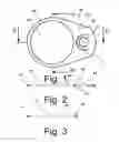
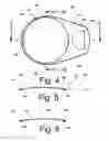
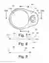
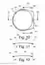
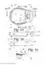
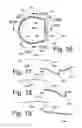
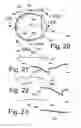
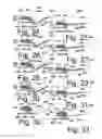
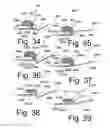
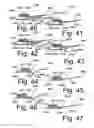
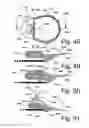
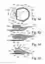
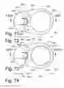
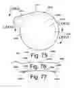
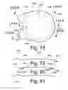
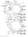
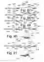
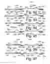
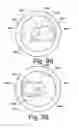
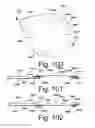
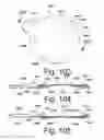
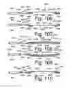
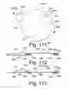
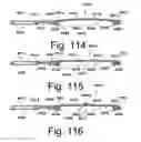
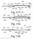
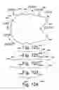
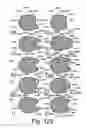
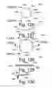
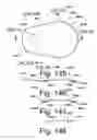

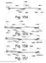
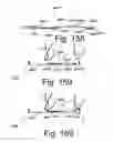
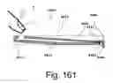
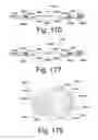
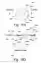

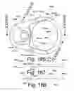
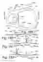
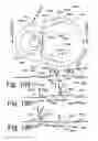
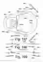
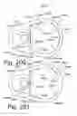
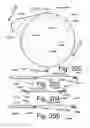

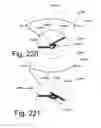
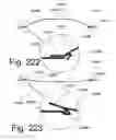
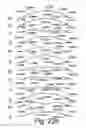
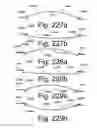
Sources:
- United States Patent and Trademark Office - verify current appl. status at the USPTO↗
Recent applications in this class:
- » 20180354679 2018-12-13
Method and apparatus for sealing an opened beverage container - » 20180141702 2018-05-24
RE-CLOSABLE CONTAINER LID - » 20180111715 2018-04-26
STAY-TAB BEVERAGE CAN WITH PROTECTIVE GUARD - » 20170361979 2017-12-21
Protective lid for containers - » 20170129644 2017-05-11
RECLOSABLE TEAR-OPEN LID - » 20160325880 2016-11-10
Lid for containers of substances and container of substances comprising said lid - » 20160236813 2016-08-18
BEVERAGE CAN MARKETING DEVICE WITH REMOVABLE CENTER COVER - » 20160176572 2016-06-23
Tamper-evident reusable package closure - » 20160059988 2016-03-03
CAN COVER - » 20150274355 2015-10-01
LIGHTWEIGHT, HINGED SELF-CLOSING CONTAINER COVERS AND ELASTOMER SPRINGS FOR USE WITH SUCH COVERS